US1851056A - Fire extinguisher - Google Patents
Fire extinguisher Download PDFInfo
- Publication number
- US1851056A US1851056A US245286A US24528628A US1851056A US 1851056 A US1851056 A US 1851056A US 245286 A US245286 A US 245286A US 24528628 A US24528628 A US 24528628A US 1851056 A US1851056 A US 1851056A
- Authority
- US
- United States
- Prior art keywords
- head
- cast
- extinguisher
- fire extinguisher
- neck
- Prior art date
- Legal status (The legal status is an assumption and is not a legal conclusion. Google has not performed a legal analysis and makes no representation as to the accuracy of the status listed.)
- Expired - Lifetime
Links
- 208000028659 discharge Diseases 0.000 description 7
- 239000007788 liquid Substances 0.000 description 2
- 239000000463 material Substances 0.000 description 2
- 239000002184 metal Substances 0.000 description 2
- 230000004048 modification Effects 0.000 description 2
- 238000012986 modification Methods 0.000 description 2
- 239000000126 substance Substances 0.000 description 2
- 241001678235 Hister Species 0.000 description 1
- 241000249821 Lipotes Species 0.000 description 1
- 241001446467 Mama Species 0.000 description 1
- 230000000903 blocking effect Effects 0.000 description 1
- 238000005266 casting Methods 0.000 description 1
- 230000008878 coupling Effects 0.000 description 1
- 238000010168 coupling process Methods 0.000 description 1
- 238000005859 coupling reaction Methods 0.000 description 1
- 238000004519 manufacturing process Methods 0.000 description 1
- 210000002445 nipple Anatomy 0.000 description 1
- 230000002093 peripheral effect Effects 0.000 description 1
- 239000013049 sediment Substances 0.000 description 1
- 238000005476 soldering Methods 0.000 description 1
Images
Classifications
-
- A—HUMAN NECESSITIES
- A62—LIFE-SAVING; FIRE-FIGHTING
- A62C—FIRE-FIGHTING
- A62C13/00—Portable extinguishers which are permanently pressurised or pressurised immediately before use
- A62C13/003—Extinguishers with spraying and projection of extinguishing agents by pressurised gas
Definitions
- My invention relates to' fire extinguisher casings, and particularly to the heads thereof.
- '-Another object is the provision of a channel in the periphery of the lower edge of the integrally cast head which will retain a flaring flange of the upper annular edge of the shell.
- a still further object is the provision of cast lugs within the head which may be usedto bend over and thereby retain'a screen. adjacent of the discharge orifice.
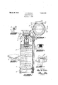
- FIG. l is a plan view of a fire extinguisher 50 showing my novel casing structure.
- Figure 3 is a detail :sectionon an enlarged scale showing the connection betweenthe Figure .4 is a detailedview of a portion. of the head from within showing the screen supportu, i r
- Fig. 4a is an enlarged fragmentary view of thecast recess for the screen. 7 i
- Figure 5 ma fragmentary plan vlew of the r 'extmguishershowinga modified form ofsup-
- the she ll-.1 forming the main bo y of I container, 1s provided atits base with a-spunmetal bottom 2having annular flanged por tions 3 which are soldered to the interiorwalls r of the :shell.
- An extensionv .4 forms isup-i porting base
- the head is iormed-withlarr' integral casting comprising the.-concave1disk.-'
- portion 5 withytheneck 5a; integrally cast,
- Theghosefz'tO has a coupling piece into Wlricha nipple 11 is -'scre wed is screwed into athreaded apertureTQF'in' :the-ca'st extension 13' ofth'e head.
- the in-' ternal side of the head also has a recessed portion 14 integrally cast therewith with lugs 15 which are used to bend over and secure a screen'lfi which prevents any sediment a from being thrown onto thefire or blocking 17 which, when the extinguisher is inverted,
- the exterior periphery of the neck 5a is threaded as indicated at 18, and a cap member 19 is thereby secured on the neck.
- a flexible gasket provides a seal which prevents leakage.
- the lugs 20 which may be drilled out for retaining the shanks 21 of the handle 22.
- the carrying handle is not required, sothat the lugs 20 may be cast as an eye, thereby providing means by which the extinguisher may be supported.
- Such a modification is indicated in Figure 5 in which the lugs 20a form an eye 20?).
- a fireextinguisher casing having a tubular shell, a cast head with a neck integrally formed therewith, a discharge conduit having a passage extending from the interior of the extinguisher casing in substantial alignment with the side walls of the casing and integrally formed with said head, a support extending outwardly from the peripheral edge of the head also integrally cast with said head, and a re-- Stepd portion with lugs cast'integrally with said head bent over and. retaining a screen formed on the inner face of said head to filter material projected through said dis charge conduit.
Landscapes
- Health & Medical Sciences (AREA)
- Public Health (AREA)
- Business, Economics & Management (AREA)
- Emergency Management (AREA)
- Fire-Extinguishing By Fire Departments, And Fire-Extinguishing Equipment And Control Thereof (AREA)
Description
7 March '29; 1932.
A. B, PHISTER 1,851,056
FIRE EXTINGUISHER Filed Jan. 9, 1928 g INVEN TOR. I 4 :0: mama! aaflw r M 2 'A TTORNEY.
Patented Mar. 29, 1932 UNITED STATES PATENToFF 'C if:
ALBERT B.1?HISTER,OF FORTTHOMAS, xnnrucxznssrenon To THE ;Hrsms mw;
FAGTURING COMPANY, or CINCINNATI, 01110, A conronar on on nnnawnnn- FIRE nxrrneursnnn Application filed January 9, 1928. Serial No. 245,286.
My invention relates to' fire extinguisher casings, and particularly to the heads thereof.
In the past it has been customary in making fire extinguishers to provide a tubular shell, a convex sheet metal head which is soldered to the shell, and a reinforced neck which is used for a charging orifice and retainer for the cap, and which is soldered by means I of an annular flange extending from the lower annular edge ofthe neck within a central opening in the sheet head. The handles with which the extinguisher is transported or hung have been inserted and soldered in holes in the head as hasbeen the discharge conduit.
The many soldered joints in holes in the thin sheet heads have been a source of weakness in the permanence of the extinguishers, because of their liability to leakage, Further, the expense required for hand labor in their manufacture has been great.
It is the object of my lnvention to provide a convex head formed from a metal cast ng which will have a neck portion integrally formed with. it. Further, it is my object to also cast integrally with the head a discharge portion to which a discharge conduit maybe readily threaded, if desired; I furtherhave as an object to cast integrally with the head a support extending outwardly from the periphery of the head which may be drilled for the inserting of carrying handles without it being necessary to drill through the head, thereby communicating with the interior and making a source of possible leakage. '-Another object is the provision of a channel in the periphery of the lower edge of the integrally cast head which will retain a flaring flange of the upper annular edge of the shell. A still further object is the provision of cast lugs within the head which may be usedto bend over and thereby retain'a screen. adjacent of the discharge orifice. The above and other objects to which reference will be made during the ensuing disclosure I accomplish by that certain combination and arrangement of parts of'which I have shown a preferred embodiment.
Referring to the drawings v V V I Figure l is a plan view of a fire extinguisher 50 showing my novel casing structure.
head and side walls.
Figur'e2gis, a vertical section taken :along';
the lines 22 in Figure 1. V
Figure 3 is a detail :sectionon an enlarged scale showing the connection betweenthe Figure .4 is a detailedview of a portion. of the head from within showing the screen supportu, i r
' Fig. 4a is an enlarged fragmentary view of thecast recess for the screen. 7 i
porting means.
Figure 5 ma fragmentary plan vlew of the r 'extmguishershowinga modified form ofsup- The she ll-.1 forming the main bo y of I container, 1s provided atits base with a-spunmetal bottom 2having annular flanged por tions 3 which are soldered to the interiorwalls r of the :shell. An extensionv .4 forms isup-i porting base The head :is iormed-withlarr' integral casting comprising the.-concave1disk.-'
like. portion 5 withytheneck: 5a; integrally cast,
therewith. 'f
The, lower. annularedge of the provided with an-annular groove 6a in whichan annular flange 7 0% the shell 1 is securely soldered; Before soldering .tli'eouter lipot the groove is turned inwardly as indicated. Aninturned flange .8 extending inwardly trom the base-of the neck supports a cage?) which, supports a receptacle 9a which :con-' .tains achemicalr 'The containernis supplied with another chemical which, whenthe con tamer-is 1I'1V8I't6d,-. is acted on :by xthefirst chemicalforming :gas which generates pressure and :the liquid in the extinguisher-is projected through the nozzle.
- Theghosefz'tO has a coupling piece into Wlricha nipple 11 is -'scre wed is screwed into athreaded apertureTQF'in' :the-ca'st extension 13' ofth'e head.' The in-' ternal side of the head also has a recessed portion 14 integrally cast therewith with lugs 15 which are used to bend over and secure a screen'lfi which prevents any sediment a from being thrown onto thefire or blocking 17 which, when the extinguisher is inverted,
falls out of the neck, thereby releasing the contents.
The exterior periphery of the neck 5a is threaded as indicated at 18, and a cap member 19 is thereby secured on the neck. A flexible gasket provides a seal which prevents leakage.
Extending from the outer periphery of the cap I further cast the lugs 20 which may be drilled out for retaining the shanks 21 of the handle 22. In some modifications the carrying handle is not required, sothat the lugs 20 may be cast as an eye, thereby providing means by which the extinguisher may be supported. Such a modification is indicated in Figure 5 in which the lugs 20a form an eye 20?).
The principle of supporting a chemical container in an extinguisher with liquid which will efi'ervesce with the'invertion of the container is old and well lmown, and I make no claim to the principle of operation of the type of extinguisher illustrated.
Having-thus described my invention, what I claim as new and desire to secure by Letters Patent, is:
1. .In combination with a fire extinguisher casing having a tubular shell, a cast head with a neck integrally formed therewith, a discharge conduithaving a passage extending .fromithe interior of the extinguisher casing in substantial alignment with the side walls of the casing and integrally formed with said head, said head further having a recessed portion with lugs cast integrally with said head bent over and retaining a screen formed on the inner face of said head to filter material projected through said discharge conduit. I
2. In combination with a fireextinguisher casing having a tubular shell, a cast head with a neck integrally formed therewith, a discharge conduit having a passage extending from the interior of the extinguisher casing in substantial alignment with the side walls of the casing and integrally formed with said head, a support extending outwardly from the peripheral edge of the head also integrally cast with said head, and a re-- cessed portion with lugs cast'integrally with said head bent over and. retaining a screen formed on the inner face of said head to filter material projected through said dis charge conduit.
ALBERT B. PI-IISTER.
Priority Applications (1)
| Application Number | Priority Date | Filing Date | Title |
|---|---|---|---|
| US245286A US1851056A (en) | 1928-01-09 | 1928-01-09 | Fire extinguisher |
Applications Claiming Priority (1)
| Application Number | Priority Date | Filing Date | Title |
|---|---|---|---|
| US245286A US1851056A (en) | 1928-01-09 | 1928-01-09 | Fire extinguisher |
Publications (1)
| Publication Number | Publication Date |
|---|---|
| US1851056A true US1851056A (en) | 1932-03-29 |
Family
ID=22926061
Family Applications (1)
| Application Number | Title | Priority Date | Filing Date |
|---|---|---|---|
| US245286A Expired - Lifetime US1851056A (en) | 1928-01-09 | 1928-01-09 | Fire extinguisher |
Country Status (1)
| Country | Link |
|---|---|
| US (1) | US1851056A (en) |
-
1928
- 1928-01-09 US US245286A patent/US1851056A/en not_active Expired - Lifetime
Similar Documents
| Publication | Publication Date | Title |
|---|---|---|
| US2174354A (en) | Tank siphon support | |
| US2764324A (en) | Water dispenser | |
| US1647210A (en) | Fountain syringe | |
| US1851056A (en) | Fire extinguisher | |
| ES2126274T3 (en) | CONTAINER LID AND DISPENSER DEVICE. | |
| FR2397994A1 (en) | CLOSING DEVICE FOR A CONTAINER INCLUDING A CYLINDRICAL SIDE WALL | |
| US2025232A (en) | Lubricating device | |
| US685694A (en) | Pipe-union. | |
| US2110927A (en) | Well trap drain for refrigerator cars | |
| US977261A (en) | Valve-fitting. | |
| US1898303A (en) | Valve for liquid containers | |
| MX168419B (en) | INTEGRAL SUPPLY PLUG | |
| US1754005A (en) | Oil-tank fire protection | |
| US1053344A (en) | asbury | |
| US1610390A (en) | Heat-insulated container | |
| US2296047A (en) | Grease dispensing apparatus | |
| US2235663A (en) | Ventilation and testing device | |
| US1929709A (en) | Liquid storage tank | |
| US991844A (en) | Therapeutic bottle. | |
| US616016A (en) | Rubber-cement tank | |
| US1340078A (en) | Container | |
| CN208260797U (en) | A kind of dropper apparatus for placing | |
| US951044A (en) | Combined hot-water bottle and syringe-reservoir. | |
| US779740A (en) | Coffee-urn. | |
| USRE9936E (en) | Absignoix |