US1851037A - Mining machine - Google Patents
Mining machine Download PDFInfo
- Publication number
- US1851037A US1851037A US328805A US32880528A US1851037A US 1851037 A US1851037 A US 1851037A US 328805 A US328805 A US 328805A US 32880528 A US32880528 A US 32880528A US 1851037 A US1851037 A US 1851037A
- Authority
- US
- United States
- Prior art keywords
- cutters
- cutter
- cylinder
- conveyor
- coal
- Prior art date
- Legal status (The legal status is an assumption and is not a legal conclusion. Google has not performed a legal analysis and makes no representation as to the accuracy of the status listed.)
- Expired - Lifetime
Links
- 238000005065 mining Methods 0.000 title description 7
- 230000007246 mechanism Effects 0.000 description 33
- 239000003245 coal Substances 0.000 description 26
- 239000000463 material Substances 0.000 description 6
- 238000010276 construction Methods 0.000 description 5
- 239000007921 spray Substances 0.000 description 4
- 230000009471 action Effects 0.000 description 3
- 230000006835 compression Effects 0.000 description 3
- 238000007906 compression Methods 0.000 description 3
- 239000000428 dust Substances 0.000 description 3
- 230000004044 response Effects 0.000 description 3
- 239000012530 fluid Substances 0.000 description 2
- 239000011435 rock Substances 0.000 description 2
- 230000035939 shock Effects 0.000 description 2
- XLYOFNOQVPJJNP-UHFFFAOYSA-N water Substances O XLYOFNOQVPJJNP-UHFFFAOYSA-N 0.000 description 2
- FSVJFNAIGNNGKK-UHFFFAOYSA-N 2-[cyclohexyl(oxo)methyl]-3,6,7,11b-tetrahydro-1H-pyrazino[2,1-a]isoquinolin-4-one Chemical compound C1C(C2=CC=CC=C2CC2)N2C(=O)CN1C(=O)C1CCCCC1 FSVJFNAIGNNGKK-UHFFFAOYSA-N 0.000 description 1
- 208000002874 Acne Vulgaris Diseases 0.000 description 1
- 241000251468 Actinopterygii Species 0.000 description 1
- 241001665400 Coracias abyssinicus Species 0.000 description 1
- 102000020897 Formins Human genes 0.000 description 1
- 108091022623 Formins Proteins 0.000 description 1
- LFVLUOAHQIVABZ-UHFFFAOYSA-N Iodofenphos Chemical compound COP(=S)(OC)OC1=CC(Cl)=C(I)C=C1Cl LFVLUOAHQIVABZ-UHFFFAOYSA-N 0.000 description 1
- 230000002159 abnormal effect Effects 0.000 description 1
- 206010000496 acne Diseases 0.000 description 1
- 230000015572 biosynthetic process Effects 0.000 description 1
- 230000015556 catabolic process Effects 0.000 description 1
- 239000012634 fragment Substances 0.000 description 1
- 210000004907 gland Anatomy 0.000 description 1
- 150000002500 ions Chemical class 0.000 description 1
- 238000004519 manufacturing process Methods 0.000 description 1
- 239000003595 mist Substances 0.000 description 1
- 230000010355 oscillation Effects 0.000 description 1
- 238000012856 packing Methods 0.000 description 1
- 238000004321 preservation Methods 0.000 description 1
- 230000000750 progressive effect Effects 0.000 description 1
- 230000001105 regulatory effect Effects 0.000 description 1
- 230000008439 repair process Effects 0.000 description 1
- 239000010454 slate Substances 0.000 description 1
Images


Classifications
-
- E—FIXED CONSTRUCTIONS
- E21—EARTH OR ROCK DRILLING; MINING
- E21C—MINING OR QUARRYING
- E21C27/00—Machines which completely free the mineral from the seam
- E21C27/20—Mineral freed by means not involving slitting
- E21C27/28—Mineral freed by means not involving slitting by percussive drills with breaking-down means, e.g. wedge-shaped tools
Definitions
- the invention relates to machines. for min inggtunnelling and the like, and espec ally to those for digging coal andsimilar ,frangi 'b c m er a s
- An object of the invention is to provide a machinefort-cutting coal and the like which embodies .pai-red.
- reciprocating Cutters whlch are automatically oscillated vwith respect to the facebeinqicut, are resiliently actuated by operationpf-a primemover and are "cushioned at both ends of'th'eirstrokes'to :absorb'shoclr due to, both normal; and: abnormal cutter impact, andwhich-machine embodies the advantages of, While being. ofrsimpler construction and higher eflicien'cy than, the2cutter mechanism disclosed in, the. Unitedstates Patent No.
- Anotherobject is toprovide amachme A; further obj ect-is: to provide a machine of the. type-.referred-to, in which the. sweep of 1 the cutter is regulable' to cut the entire face down to flo'orlevel or-vto cut any desired .portion of. the face, which is provided with con-- veying-mec-hanism for collecting, and loading the coal or other materialbrought down, and with means for automatlcally retracting the conveying mechanism in. coordination wlth downwardmovement .ofthe' cutters-to vpermit them to;cut to-the floor level.
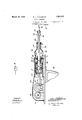
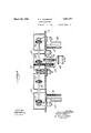
- FIG. 3- is a fragmentary plan viewshowing the disposition of and driving-means for the cutter battery-Fig.4 a detail;- plani view of one pair of; cutters; Fig. 5 a vertical. sectional. view through. a cutter mechanisrmtaken on line. V.V, Fig. l: Fig. (Sis a vertical section'of the tableetaken on line VI,-V'I, Fig. 3, showingthe cutter drive; and Fig. 7 is a plan View of theconveymg. mechanism together with. its driving elements.
- the machine embodies cutter mechanisms dis posjedfin 'co'operating pairs, each mechanism includ ng. a prune mover comprlslnggaclosed 'pis ton,..' and means. to :reciprocate the cylinF ders, and by reason of fluid trapped in the cylresponse. to movement of the cylinder and the cutteriinpactis cushioned or:absorbedin .co m- Y to move thecutters verticallywith respect to .thelfacelbeing cut... Conveyors are also provided to, gather. and transport the; mate:
- the machine comprises a-truck ofsu1talz leconstructionv providedwith means for propellingit along the'tunnel or other placeoff use andi most suitably this comprises'caterpillar, tractor so I mechanism indicated generally. by them-u:
- the cutter assembly comprises a plurality offcutter mechanisms indicated generally by the numerall l, Fig. 3, disposedfin cooperating pairs ona table 5 'pivotally mounted on hangers, 5a, Fig. 6., Eachcutter mechanism comprises a cylinder 6, Figs; 4 and 5,.pref
- a connecting rod 8 attached 'to the rearend of the, cylinder.
- the forward end of the cylinder is closed by' a head 9 formed to promile a bearing-'sle'eve-9aifora cuttershaft adapted to provide a end of the cylinder is provided with acne place by a packing gland 100, and in bushing lla-by a cap 101;
- piston .11 is provided with piston rings 15, and the bearing surfaces between the casing and cylinder are fluid-tight fit.
- spring-impelled check valve 12 which acts to admit air to compensate for that lost by leakage.
- the cylinder may be. and preferably is, further supplied with lateral ports or openings 13 and 14, Fig. 5, connecting the cylinder on opposite sides of the piston through the space between the cylinder and casing intermediate of the end flanges.
- Cutting tools are provided on the forward ends of the shafts 10.
- the form shown embodying a plurality of chisel-like cutters 16 removably held in a tool holder 17 provided with a shaft-receiving socket 18 and held on the shaft by a .key 19.
- These cutters are preferably of the chisel-like fish tail form seen in Figs. 4 and 5.
- Their form adapts the cutters to chip out fragments of the wall which they strike, and for that reason the form illustrated is at present preferred.
- the cutter mechanisms are disposed in cooperating pairs, each pair of cylinders being reciprocated by a gear .ZOandcranks 21 connected'to connecting rods 8, the cranks being arranged to reciprocate the cylinders of each pair in opposite directions, as shown in Fig. 4.
- Gears 20 mesh with pinions 22 carried on a common shaft 23, to which is keyed a gear 24 driven by a pini0n'25, spiral gear 26, and spiral pinion 27 connected to the shaft of a motor 28.
- Housings29 may be provided for these drives.
- the cutter mechanisms are disposed in cooperating Pa rs.
- the machines according to the invention may be equipped with one such pair, or with a plurality,.depending on the width of cut. When a battery of pairs are used, itwill generally be desirable to dispose them in fanwise fashion. as shown in Fig. 3.
- the cutters are moved vertically over the wall of coal being cut, and to this end hoisting mechanism associated with table 5 is provided.
- This includes a segmental gear 30, Figs. 1 and 7, secured to table 5 and supported on a shaft 31.
- Gear 30 meshes with a pinion 32 on a shaft 33 driven by a worm gear 34, worm 35, shaft 36, worm gear 37, and a worm 38, connected to the shaft'of a reversing motor 39.
- the segmental gear is designed to provide the maximum cutter sweep desired,
- any suitable means are employed for regulating the swing of the table and cutters to move over the face fully to the floor level, or to cut any desired portion of the face and to automatically reverse the movement at the end of the throw.
- conveyor and loading mechanism Associated with the truck is conveyor and loading mechanism adapted to remove the coal brought down through the action of the cutter.
- This mechanism comprises right and left handscrew conveyors 40 and 41, Fig. 7, carried at the forward, or cutting, end of the machine by shafts 42 and 43 respectively, which operate in bearings supported by a frame structure indicated generally at 44.
- These conveyors gather the material as it falls to the floor and deliver it to an inclined screw conveyor 45 on a shaft 46 .
- Figs. 1 and 7 also carried in frame 44, which extend s'to the rear of the truck, so that the material can be discharged into a following truck or car.
- the conveyors are driven by an electric mounted on separate horizontal shafts 58 and i 59, suitably ournalled and carrying on their outside ends sprocket wheels 60 and 61, Fig.
- shifting arms 7 7 on each sideof frame 44 are resiliently connected to the forward end thereof by bolts 78 and heavy duty coiled springs 79 interposed between the arms and the. frame, as shown in Fig. 1, and therear Conveyor reams? ends of. these arms are. supportedbetween 22, and thesein turn actuate the cutters of posite directions, as seen in Fig. 4.
- Each arm 7 7 is'provicled. with a Vertical slot .83 which lies above rollers 7-6 when roller arins7j5 areinttheir for- Ward horizontal positiomand connected to the rear side of theseslots are bcarijngplates 84:, Which with: the corresp nding portion of the arms carry a pairof rollers 85, to form a. roller'bearing-surface for the periphery of cam 7
- the motor drives andotheriinechanism on the rear of the truck are preferably ,QIlC lQSQCiWlilhlIl-ficover 86., V
- tractor-drive motor 2 is started and run in gear to advance the machine at a constant and uniform rate, this rate being equal to: the desired progress ofthe cuttersinto the coal and being adaptable to suit Conditions by means of suitable selective gear mechanism.
- the cutter-actuating motor drives pinions of coal, theimpact thereagainst is sud .den and sharp, causing a'srnallamount of seal-to be chipped out,
- the cylinder i-s,-.of
- valves 12 willf act to maintain it. substantial? 7 ly in that position; This,.however, is acco-In'r '1 plished more readily and quickly through the'use of the ports, the interchange-of air betweenathe two sides upon movement: of the piston in either direction; tendingxto maintain the piston in'itSr-mi-cl' position.
- Cylinder 6 is fitted-in guide casing-7, an shaft in bearing: member 9a in such man: nor as to; make fliuidetight; bearing surfaces, but nevertheless there maybe gradual loss of air from the cylinder; Such loss of ai-rpis fully compensated by thewone way valves 12,
- This cutter construction thus providesfull and positive-cushioning of the-cutter, the
- rollers 85 will ride on the circular surface of the camuntil rotation thereof brings notch 74E of the cams up to the rollers.
- arms '75 have moved to slots 83 in conveyor arms 77, and as the table continues to move downwardly pinions 71 will continue to rotate, causing arms 7 5 and rollers 76 to move upwardly, and rollers 76 move along slots 83, thus moving conveyor arms 77 and the entire conveyor mechanism backwardly, permitting the cutters to operate to the floor level.
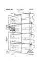
- the fully retracted position is shown in Fig. 2.
- rollers 85 leave the cam surface and enter its notch as the table reaches a position about 1'2 degrees below horizontal in its downward movement.
- the conveyors will then be fully retracted by the time the cutters reach the floor. Nhen the table begins to move upwardly, pinion 32 is driven in the reverse direction, arms '4" 5 then urging the conveyor mechanism forwardlyuntil rollers 85 again bear on the periphery of the cam.
- the conveyor is automatically and positively actuated in response to cut ter movement, and the conveyor assembly is held in fixed relation to the machine at all times and cannot move except asactuated by the cutter mechanism.
- the machine is preferably provided with means for preventing dust formation during its operation, and this is most suitably accomplished. by means of a water spray directed against the coal.
- a pipe 105 connected to extension 7a of the guide casing, as by straps 106 bolted to the casing, extend forwardly therefrom alongside the c uttershaft.
- the forward end is provided with a spray nozzle 107, and the pipe is preferably bent to direct the spray close to the point of contact of the cutting tool with thecoal.
- the pipe is connected toawater line by a flexible conduit 10S, and the nozzle preferably distributes the water in the form of a very fine mist. In this manner the spray moves with the cutters, and dust formed by the cutting is at once wet and thus prevented from floating into theair.
- each of the conveyor arms 7 7 is provided with a push button'switch 95, Figs. 1 and 2, inserted in the circuit of tread motor 2, and disposed below each button on the conveyor framework, is a stop 96.
- a push button'switch 95 Figs. 1 and 2
- the conveyor structure moves upwardly against spring 79, and continued movement brings stop 96 against the button, shutting off the tread motor.
- the operator then reverses the machine, the obstruction is removed, switch 95 reset, and the machine advanced to operate as before.
- the machine according to the invention possesses numerous advantages, It can be built in units of any size, to cut any desired width. and through the use of rapidly re peated, high speed cus'hioned'impact blows, the coal struck by the cutters is chipped out instead of being gouged or scraped out as in prior cutting systems.
- the construction permits maximum impact blows without recoil or shock in the machine, so as to insure complete protection to the machine together with substantial freedom from breakdowns due to parts broken as the result of impact stresses.
- the product is uniformin size, a minimum amount of'coal is cut in bringing the main portion down in the form of lumps, thus producing a minimum of fines, and the machine automatically gathers and delivers the coal. It is capable of high output, and owing to the cutter construction, a minimum of power is required. Numerous other advantages may be seen by those skilled in the art.
- screw conveyors adapted to remove the coal brought down by said cutters, and means for retracting said conveyorswhen the cutters move toward the fioor,said conveyors being supported by a pair of arms slidably carried by the truck.
- roller actuated by rotation of said gear and pinion and adapted when the tablepasses be- 1 low its horizontal positiontoengage said conveyor arms to urge the arms and conveyor mechanism rearwardly of the-machine.
- tor-actuated screw conveyors carried'by said a cylinder reciprocable therein, a floating piston elastically cushioned within said cylininders of each pair being reciprocated in opposite directions, motor operated conveyor mechanismfor gathering and removing the coal brought down by said cutters, and means for retracting said conveyors to permit the cutters to operate to floor level
- conveyor-supporting membersslidably borne by said truck a common shaft carrying a cam, a pinion and an oscillating power-applying arm, and a rack carried bysaid table engagmovement of'said conveyor-supporting members and adapted upon rotation by said rack and pinion to permit engagement of said arm and conveyor-supporting members when the table reaches 12%? below horizontal in its downward travel.
- each cutter mechanism comprising a c guide casing, a cylinderreciprocable therein,
- apiston slidably enclosed in said cylinder and air-cushioned from its ends, a shaft extendmg forwardly from said piston, a cutter tool connected to the extended end of said shaft,
Landscapes
- Engineering & Computer Science (AREA)
- Mining & Mineral Resources (AREA)
- Mechanical Engineering (AREA)
- Life Sciences & Earth Sciences (AREA)
- General Life Sciences & Earth Sciences (AREA)
- Geochemistry & Mineralogy (AREA)
- Geology (AREA)
- Crushing And Pulverization Processes (AREA)
Description
March 29, 1932. B, A. CHIUBBUCK' MINING MACHINE Filed Dec.
27, 1928 7 Sheets-Sheet 1 llVVE/VIOK 801774 CHUEBl/CK,
ADMIN/J77? TRIX.
m am
March 29, 1932. B. A. CHUBBUCK MINING MACHINE Filed Dec. 7 Sheets-Sheet 2 N WIH HHU W$%\\\\\\\\- .3? 1 7 o o e o T... mm x. M mm, 90 a mu m u 5% B. A. CHUBBUCK ,851,037
MINING MACHINE Filed D60. 27, 1928 7 Sheets- She'et 3 March 29, 1932.
March 29, 1932. B. A. CHUBBUCK MINING MACHINE Filed Dec. 27, 1928 7 Sheets-Sheet 4 WITNESSES .7 R. Jae/c March 29, 1932- B. A. CHUBBUCK MINING MACHINE '7 Sheets-Sheet 6 Filed Dec-..
1' IIIHI ll WITNESSES March 29, 1932. B. A. CHUBBUCK MINING MACHINE Filed Dec. 27, 1928 '7 Sheets-Sheet 7 Patented Mar. 29, 1932 curta n; cnumsuok; DEcEAsEn tAmE oF'rIrTsBUnGH, PENNSYLV NI ,BYYERMVAEIM. V CHUBBUCK,ADMIN1STRATRIX,OF mnnmannw YORK,- A'ssIcNonTo wimp: s.
GEEK/MACHINERY COMP-ANY, or PIT SBU H;rnivivsynvnmn, 'A coRroRA'rIoN OF DELAWARE Mmmq MACHINE "Application filed December avg-192a. Seri-a1rNo..328;80 5.- I
The invention relates to machines. for min inggtunnelling and the like, and espec ally to those for digging coal andsimilar ,frangi 'b c m er a s An object of the invention is to provide a machinefort-cutting coal and the like which embodies .pai-red. reciprocating Cutters whlch are automatically oscillated vwith respect to the facebeinqicut, are resiliently actuated by operationpf-a primemover and are "cushioned at both ends of'th'eirstrokes'to :absorb'shoclr due to, both normal; and: abnormal cutter impact, andwhich-machine embodies the advantages of, While being. ofrsimpler construction and higher eflicien'cy than, the2cutter mechanism disclosed in, the. Unitedstates Patent No.
1,651,672, issuedrDecember 6, 1927 y Anotherobject is toprovide amachme A; further obj ect-is: to provide a machine of the. type-.referred-to, in which the. sweep of 1 the cutter is regulable' to cut the entire face down to flo'orlevel or-vto cut any desired .portion of. the face, which is provided with con-- veying-mec-hanism for collecting, and loading the coal or other materialbrought down, and with means for automatlcally retracting the conveying mechanism in. coordination wlth downwardmovement .ofthe' cutters-to vpermit them to;cut to-the floor level.
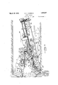
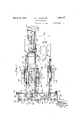
- In the accompanying. drawings-,Frgs; .1. and
Q are side elevational viewsof a'machine embody ing'the invention, showing two different operating. positions Fig. 3- is a fragmentary plan viewshowing the disposition of and driving-means for the cutter battery-Fig.4 a detail;- plani view of one pair of; cutters; Fig. 5 a vertical. sectional. view through. a cutter mechanisrmtaken on line. V.V, Fig. l: Fig. (Sis a vertical section'of the tableetaken on line VI,-V'I, Fig. 3, showingthe cutter drive; and Fig. 7 is a plan View of theconveymg. mechanism together with. its driving elements.
Stated briefly, the machine according-to the invention embodies cutter mechanisms dis posjedfin 'co'operating pairs, each mechanism includ ng. a prune mover comprlslnggaclosed 'pis ton,..' and means. to :reciprocate the cylinF ders, and by reason of fluid trapped in the cylresponse. to movement of the cylinder and the cutteriinpactis cushioned or:absorbedin .co m- Y to move thecutters verticallywith respect to .thelfacelbeing cut... Conveyors are also provided to, gather. and transport the; mate:
rial removed, ,andmeans' associatedlwiththe conveyors. andcutter table withdraw the C011? veyorssafter, the cutters pass. belowahorizontalfpositiontopermit them to cut down to. the
'Referring'. to the illustrative embodiment shown in the. drawings, from which allparts reciprocable cylinder, a. floating piston enclosed thereimacutter shaft connected to said inder 'by thelpiston the cuttersv are-moved. in
notessentialto an understanding of the invent-ion have been eliminated, the machine comprises a-truck ofsu1talz leconstructionv providedwith means for propellingit along the'tunnel or other placeoff use andi most suitably this comprises'caterpillar, tractor so I mechanism indicated generally. by them-u:
i mer'al, 1, Figs. .1. and 2,; the 'constructi-onpf whichforms no partofmy invention andjis 7 well ,understood; .Preferablythe tractor treadisdrivenby means of antelectric mo.- tor 2,. earned. on a, frame structure, 3], .su1tj-,
ablershafts, driving gears and selective speed and reversing mechanism f. theusual type, j
i not shown, being. provided for that purpose.
The cutter assembly comprisesa plurality offcutter mechanisms indicated generally by the numerall l, Fig. 3, disposedfin cooperating pairs ona table 5 'pivotally mounted on hangers, 5a, Fig. 6., Eachcutter mechanism comprises a cylinder 6, Figs; 4 and 5,.pref
erably provided with hearing flanges ateach end, and'reciprocated in a guide casingfl' by a connecting rod 8 attached 'to the rearend of the, cylinder. The forward end of the cylinder is closed by' a head 9 formed to promile a bearing-'sle'eve-9aifora cuttershaft adapted to provide a end of the cylinder is provided with acne place by a packing gland 100, and in bushing lla-by a cap 101; Also, piston .11, is provided with piston rings 15, and the bearing surfaces between the casing and cylinder are fluid-tight fit. Each way spring-impelled check valve 12, which acts to admit air to compensate for that lost by leakage. The cylinder may be. and preferably is, further supplied with lateral ports or openings 13 and 14, Fig. 5, connecting the cylinder on opposite sides of the piston through the space between the cylinder and casing intermediate of the end flanges.
Cutting tools are provided on the forward ends of the shafts 10. the form shown embodying a plurality of chisel-like cutters 16 removably held in a tool holder 17 provided with a shaft-receiving socket 18 and held on the shaft by a .key 19. These cutters are preferably of the chisel-like fish tail form seen in Figs. 4 and 5. Their form adapts the cutters to chip out fragments of the wall which they strike, and for that reason the form illustrated is at present preferred.
The cutter mechanisms are disposed in cooperating pairs, each pair of cylinders being reciprocated by a gear .ZOandcranks 21 connected'to connecting rods 8, the cranks being arranged to reciprocate the cylinders of each pair in opposite directions, as shown in Fig. 4. Gears 20 mesh with pinions 22 carried on a common shaft 23, to which is keyed a gear 24 driven by a pini0n'25, spiral gear 26, and spiral pinion 27 connected to the shaft of a motor 28. Figs. 3 and 6. Housings29 may be provided for these drives.
As previously described, it is characteristic of the invention that the cutter mechanisms are disposed in cooperating Pa rs. The machines according to the invention may be equipped with one such pair, or with a plurality,.depending on the width of cut. When a battery of pairs are used, itwill generally be desirable to dispose them in fanwise fashion. as shown in Fig. 3.
The cutters are moved vertically over the wall of coal being cut, and to this end hoisting mechanism associated with table 5 is provided. This includes a segmental gear 30, Figs. 1 and 7, secured to table 5 and supported on a shaft 31. Gear 30 meshes with a pinion 32 on a shaft 33 driven by a worm gear 34, worm 35, shaft 36, worm gear 37, and a worm 38, connected to the shaft'of a reversing motor 39. The segmental gear is designed to provide the maximum cutter sweep desired,
5 and any suitable means are employed for regulating the swing of the table and cutters to move over the face fully to the floor level, or to cut any desired portion of the face and to automatically reverse the movement at the end of the throw.
Associated with the truck is conveyor and loading mechanism adapted to remove the coal brought down through the action of the cutter. This mechanism comprises right and left handscrew conveyors 40 and 41, Fig. 7, carried at the forward, or cutting, end of the machine by shafts 42 and 43 respectively, which operate in bearings supported by a frame structure indicated generally at 44. These conveyors gather the material as it falls to the floor and deliver it to an inclined screw conveyor 45 on a shaft 46 .(Figs. 1 and 7), also carried in frame 44, which extend s'to the rear of the truck, so that the material can be discharged into a following truck or car. i
The conveyors are driven by an electric mounted on separate horizontal shafts 58 and i 59, suitably ournalled and carrying on their outside ends sprocket wheels 60 and 61, Fig.
' 7 which drive the forward conveyors through sprocket chains 62 and63 and sprockets 64 and 65 carried by shafts 42 and 43, respectively. The longitudinal or rearwardlymoving conveyor '45'is driven by a sprocket 66 on shaft 54, sprocket chain 67 and sprocket 68'mounted on shaft 46. This drivingmechanism may be enclosed within a housing 69, as shown in Fig. 1. 1
Referring to the lower dotted line position of the cutters in Fig. 1, it will be seen that the forward conveyors when in normal position would interfere with the downward progress of the cutters and prevent cutting entirely to the floor level. V A special feature of the invention resides in means for retracting the conveyor mechanism as the cutters approach. the lower dotted line position of Fig. 1, to permit the cutter to work to the floor level. To this end, similar gear sectors70, Figs. 1, 2, 6 and 7, mounted on each side of table 5 mesh with pinions 71 on shafts 72 carried on frame 44. Keyed to shafts 72 to turn with pinion 71 are circular cams 73 each havingasegmentalnotchedportion74. Arms each provided at its end with a roller 76 are also mounted on shafts 72. shifting arms 7 7 on each sideof frame 44 are resiliently connected to the forward end thereof by bolts 78 and heavy duty coiled springs 79 interposed between the arms and the. frame, as shown in Fig. 1, and therear Conveyor reams? ends of. these arms are. supportedbetween 22, and thesein turn actuate the cutters of posite directions, as seen in Fig. 4.
-'g 1ider0lle.rs 80. arried-by the truck frame.
lioilerstil and 82 a lso carrieid by the truck frame, support and guidetheshiiitingarms intermediate points: Each arm 7 7 is'provicled. with a Vertical slot .83 which lies above rollers 7-6 when roller arins7j5 areinttheir for- Ward horizontal positiomand connected to the rear side of theseslots are bcarijngplates 84:, Which with: the corresp nding portion of the arms carry a pairof rollers 85, to form a. roller'bearing-surface for the periphery of cam 7 The motor drives andotheriinechanism on the rear of the truck are preferably ,QIlC lQSQCiWlilhlIl-ficover 86., V
7 Assuming the ma-ch'ineto he in position adjacent the face of coal to -becut, motors '28,,
and at? are: startedto set the cutters,.l;iisting mechanism and conveyors in motion, and tractor-drive motor 2 is started and run in gear to advance the machine at a constant and uniform rate, this rate being equal to: the desired progress ofthe cuttersinto the coal and being adaptable to suit Conditions by means of suitable selective gear mechanism.
The cutter-actuating motor drives pinions of coal, theimpact thereagainst is sud .den and sharp, causing a'srnallamount of seal-to be chipped out, The cylinder i-s,-.of
course, advancing at this momen udit-is positively'actuated' by the connecting rod, but-the 1 cutter, cutter shaft and piston are actuated by the aircushion inthecylinde r, and consequently the V impact i of the cutter age-inst the coali-s resiliently; absorbed This 1y taken up, thereby.
and 14 are not provided in the-cylinder,this action. will be confinedtorthe-space behind is-anjimportantfeature of the invention, be ause th m chine suffern impact shock and-thus there-is no danger of damage to he machine due to the-repeated impact, or toimpact with slate, rock or other material harder or less frangible than that being cut.
" In eithercasethe actionwill be as follows:
The impact will tend to move the-piston-rearwardly in the cylinder, and since the-rings 115 prevent-leakage of airpast thepistoii, the airtra'ppejd behind thepiston will be com pressed, this compression being resisted more the further-the piston moves 'rearwardly, and the result is that all of thleshock isresil ient herethe ports 13 ,the' inertia of the: pistoirand shaft The tlnepiston; but wherel the-ports are: provided,
the compression will force air-to the forward end ofthe cylinder through ports 13 and lean'd the, conduit formed between theflcylin der and theguide casingr. In this; case, as
the-piston moves back, the air wiil be dis-' placed until the piston reaches and. closes port, 13,. after which the air remaining will be, compressed loetweenthe piston and the portion of the cylinder. beyondthe: pornand 5L 5 the contact of the piston 'withfithe rear of cylinder will thereby be prevented. j;-
i Continued rotation of gear '20 retracts1the cylinder, releasing the :pressure on'thecuts tersyajnd the air compressed behind; the pis- 7 ton expandsand returns the-piston'to a point where the pressure on eachside'is equalized, this action being assisteclftogsome extent by most-favorable position-forithe piston dur ing' the nondmpact periodsof the cycle is substantialiyg in the middle of the cylinder. If the ports 13 and l4arenotprovided,
valves 12willf act to maintain it. substantial? 7 ly in that position; This,.however, is acco-In'r '1 plished more readily and quickly through the'use of the ports, the interchange-of air betweenathe two sides upon movement: of the piston in either direction; tendingxto maintain the piston in'itSr-mi-cl' position.
Cylinder 6is fitted-in guide casing-7,, an shaft in bearing: member 9a in such man: nor as to; make fliuidetight; bearing surfaces, but nevertheless there maybe gradual loss of air from the cylinder; Such loss of ai-rpis fully compensated by thewone way valves 12,
which, when the pressure in the cylinder falls below. atmospheric, will open, to: supplythe air lost in; compression, Oili supply and drain openings-9.1- andea are. also provided in the cylinder head. Theaguide casing extension 7a connected'to; casing 7 to; make a fluid-tight connection andthe: extensions Tact each areconnectedacoupling I 93', Fig. 45, whereby when: onecylinder moves forwardly the airuaheada ofiit: is applied; to v the head of the retreatingcylinder, andthus the air in- .th as ng; is; circulated, assuring clean air free from mine dust and other material detriment-alto preservation of-'bear+ 'ing surfaces. The casings Taare'also pro vided with boltedQcaps or hand: holesfldi. V
This cutter construction thus providesfull and positive-cushioning of the-cutter, the
construction isle-simple, repairs, are easily! made and no auxiliary air coinpressing equipment 'is required, the; actuation; b ing positive'by irtue of thepist'on fioatingwith- .in the'cylinderitself. i V J When motor 339 is started the hoistingpin ion 32' actua-tes segmental gear-30, to oscillate the hoisting'tahle (and thecutters); vortical'ly with respect to the wall being cut, suitable automaticreversing, mechanism,- being used. toreverse. the gear drive when; the
cutters have reached the roof'and floor of the cut. The progressive path of the cutters :into a face of coal is represented by the arrowed lines AB, BC, 6130;, Figs. 1 and 2, and the oscillating movement withrespect to the wall results in the production of parallel grooves in tee coal face,and the pillars thus formed are intermittently broken down.
"The material thus cut falls to the floor, where the right andleft hand screw conveyors 40 and L-Lpick it up and pass it to the longitudinal conveyor 45', which discharges it into a car or other receptacle. It will be seen'from 1 that, in moving downwardly alongthe line GH, progress of the cutters would. be barred by the conveyors, and the machine couldnot move forward. This is taken care of by the special conveyor moving mechanism, which operates as follows: The conveyors are carried byarms T7, and as long as the cutters are above horizontal, rollers85 bear against the peri hery of cam 73, and no movement of the conveyor arms is possible. Sector gears 70, mounted with the'hoisting table rotate pinions 7 1, and consequently cams 73' and arms 75. As the table moves downwardly from its uppermost position rollers 85 will ride on the circular surface of the camuntil rotation thereof brings notch 74E of the cams up to the rollers. At this moment, arms '75have moved to slots 83 in conveyor arms 77, and as the table continues to move downwardly pinions 71 will continue to rotate, causing arms 7 5 and rollers 76 to move upwardly, and rollers 76 move along slots 83, thus moving conveyor arms 77 and the entire conveyor mechanism backwardly, permitting the cutters to operate to the floor level. The fully retracted position is shown in Fig. 2. In this conveyor-moving mechanism it will generally be desirable to have rollers 85 leave the cam surface and enter its notch as the table reaches a position about 1'2 degrees below horizontal in its downward movement. The conveyors will then be fully retracted by the time the cutters reach the floor. Nhen the table begins to move upwardly, pinion 32 is driven in the reverse direction, arms '4" 5 then urging the conveyor mechanism forwardlyuntil rollers 85 again bear on the periphery of the cam. Through the use of this mechanism the conveyor is automatically and positively actuated in response to cut ter movement, and the conveyor assembly is held in fixed relation to the machine at all times and cannot move except asactuated by the cutter mechanism.
The machine is preferably provided with means for preventing dust formation during its operation, and this is most suitably accomplished. by means of a water spray directed against the coal. In the machine shown. a pipe 105 connected to extension 7a of the guide casing, as by straps 106 bolted to the casing, extend forwardly therefrom alongside the c uttershaft. The forward end is provided with a spray nozzle 107, and the pipe is preferably bent to direct the spray close to the point of contact of the cutting tool with thecoal. The pipeis connected toawater line by a flexible conduit 10S, and the nozzle preferably distributes the water in the form of a very fine mist. In this manner the spray moves with the cutters, and dust formed by the cutting is at once wet and thus prevented from floating into theair.
As mentioned previously, automatic means reverse the cutter hoisting mechanism, and since't-he machine, when in operation, is driven in gear; its operation is fully automatic. The various drives are all under the control of the operator. However, to prevent unduestress arising from contact with objects which the conveyors cannot handle, means may be, and preferably are, provided to automatically stop the machine under such circumstances. For this purpose the forward end of each of the conveyor arms 7 7 is provided with a push button'switch 95, Figs. 1 and 2, inserted in the circuit of tread motor 2, and disposed below each button on the conveyor framework, is a stop 96. Should the front conveyors meet a lump of coal, or a rock or other object which they cannot handie, the conveyors will tend to climb over it. When this happens, the conveyor structure moves upwardly against spring 79, and continued movement brings stop 96 against the button, shutting off the tread motor. The operator then reverses the machine, the obstruction is removed, switch 95 reset, and the machine advanced to operate as before.
The machine according to the invention possesses numerous advantages, It can be built in units of any size, to cut any desired width. and through the use of rapidly re peated, high speed cus'hioned'impact blows, the coal struck by the cutters is chipped out instead of being gouged or scraped out as in prior cutting systems. The construction permits maximum impact blows without recoil or shock in the machine, so as to insure complete protection to the machine together with substantial freedom from breakdowns due to parts broken as the result of impact stresses. The product is uniformin size, a minimum amount of'coal is cut in bringing the main portion down in the form of lumps, thus producing a minimum of fines, and the machine automatically gathers and delivers the coal. It is capable of high output, and owing to the cutter construction, a minimum of power is required. Numerous other advantages may be seen by those skilled in the art.
Although in the specification and appended claims the machine is referred to as for digging coal, it will be understood that it can equally be applied for use with other materials, whose nature is such that they are readily chipped or shattered, and such use is fully comprehended and' intended to be Within the scope of the expression used. It will also be understood that it is not limited to the use of air as inders.
Claims: I v r s 1. In a coal digging machine, the combination of a truck provided with a pivotally supported cutter table, motor-actuated means the fluid used in the cylfor oscillating said-table, cutter means dis- 7 posed on said table and adapted upon oscillation thereof to out a plurality of substan-' 'tially parallel vertical grooves in the coal,
screw conveyors adapted to remove the coal brought down by said cutters, and means for retracting said conveyorswhen the cutters move toward the fioor,said conveyors being supported by a pair of arms slidably carried by the truck. r
2. A coal digging machine according to claim 1, said conveyor-retracting means c'omprising a sector gear carried bysaid table,
a pinionmeshing therewitlnand an arm and;
roller actuated by rotation of said gear and pinion and adapted when the tablepasses be- 1 low its horizontal positiontoengage said conveyor arms to urge the arms and conveyor mechanism rearwardly of the-machine.
3; In a coal digging machine, the combination of a truck, motor -actuated caterpillar tread mechanism to propel said truck, a table pivotally carried at the forward end of said truck, motor-actuated means for. oscillating said table vertically with respect to theface to be cut, a plurality of motor-actuated cutter mechanisms disposed in cooperating pairs on said table, each mechanism comprising a guide casing, a cylinder re'ciprocable thereln', a piston slidably enclosed insaid cylinder and air-cushioned from its ends, a tool-carrying shaft connected to said piston and extending forwardly therefrom, a cutter connected to the extended end of said shaft, ports in said cylinder on each side of the piston for passing air from one side of the piston to the other, and means for posit vely reciprocating the cylinders of each pair 1n opposite directions whereby the pistons are actuated by pressure created qin' the air trapped in said cylinder by saidpiston, mo-
tor-actuated screw conveyors carried'by said a cylinder reciprocable therein, a floating piston elastically cushioned within said cylininders of each pair being reciprocated in opposite directions, motor operated conveyor mechanismfor gathering and removing the coal brought down by said cutters, and means for retracting said conveyors to permit the cutters to operate to floor level comprising conveyor-supporting membersslidably borne by said truck, a common shaft carrying a cam, a pinion and an oscillating power-applying arm, and a rack carried bysaid table engagmovement of'said conveyor-supporting members and adapted upon rotation by said rack and pinion to permit engagement of said arm and conveyor-supporting members when the table reaches 12%? below horizontal in its downward travel.
5. In a coal digging machine, the combination of a truck, means for propelling said truck, Vertically oscillable reciprocating cutters carriedincooperating pairs by said truck, means for collecting and conveying rearwardof the truck the'coal brought down by said cutters, and mechanism operatively connected-to said collecting means for retractingit in response to downward movement of said cutters to permitthe'cutters to move to floor level. I
6. Ina coal digging machi'ne, the combination of-a motor-operated truck, a motor-operated hoisting table pivotally'carried bysaid truck mechanism including-a motor opera tively connected to said table-for oscillating ing said pinion, said cam normally preventing it vertically with respect to the face'to be cut, 1
a'plurality of' motor-actuate'd cutter meoha- .nisms disposed in cooperating pairsonsaid table, each cutter mechanismcomprising a c guide casing, a cylinderreciprocable therein,
apiston slidably enclosed in said cylinder and air-cushioned from its ends, a shaft extendmg forwardly from said piston, a cutter tool connected to the extended end of said shaft,
ports in said cylinder on each side" of the piston connected to pass air from one side of the piston to the other, and means for positively reciprocating the cylinders of each pair in opposite directions whereby the'pistons are actuated by pressure created in the air trapped in said'cylinder by said piston, motoroperated conveyor mechanism for gathering and removing the coal brought down by said cutting mechanlsm, and means associated with said conveyor mechanism for retracting it in response to downward movement of the cutters'to permit the cutters to work to floor level. e
i In testimony whereof I sign my name.
ERMA M. CHUBBUCK,
Admtmstmtm'w of the Estate of Bart A.
' Ohubbucls, Deceased.
der, and a shaft extending forwardly from.
said piston and carrying a cutter tool,'thecyl-
Priority Applications (1)
| Application Number | Priority Date | Filing Date | Title |
|---|---|---|---|
| US328805A US1851037A (en) | 1928-12-27 | 1928-12-27 | Mining machine |
Applications Claiming Priority (1)
| Application Number | Priority Date | Filing Date | Title |
|---|---|---|---|
| US328805A US1851037A (en) | 1928-12-27 | 1928-12-27 | Mining machine |
Publications (1)
| Publication Number | Publication Date |
|---|---|
| US1851037A true US1851037A (en) | 1932-03-29 |
Family
ID=23282516
Family Applications (1)
| Application Number | Title | Priority Date | Filing Date |
|---|---|---|---|
| US328805A Expired - Lifetime US1851037A (en) | 1928-12-27 | 1928-12-27 | Mining machine |
Country Status (1)
| Country | Link |
|---|---|
| US (1) | US1851037A (en) |
Cited By (6)
| Publication number | Priority date | Publication date | Assignee | Title |
|---|---|---|---|---|
| DE743980C (en) * | 1939-06-07 | 1944-01-06 | Eickhoff Geb | Schraem device for driving underground tunnels, especially drainage tunnels |
| DE875792C (en) * | 1942-05-10 | 1953-05-07 | Eisenwerk Wanheim G M B H | Process for mining coal |
| US3088718A (en) * | 1960-06-29 | 1963-05-07 | Edward C Lilly | Continuous mining machine |
| US4025116A (en) * | 1975-08-14 | 1977-05-24 | The United States Of America As Represented By The Secretary Of The Interior | Method of operating a constant depth linear cutting head on a retrofitted continuous mining machine |
| FR2437486A1 (en) * | 1978-09-26 | 1980-04-25 | Inst Gidrodinamiki Sibirskogo | Percussion tool for mine workings in solid rock - has direct action striker piston and dampers linking this to jib |
| EP0066156A1 (en) * | 1981-05-20 | 1982-12-08 | Oy Tampella Ab | Method for cutting a tunnel in rock by means of a rock drilling machine |
-
1928
- 1928-12-27 US US328805A patent/US1851037A/en not_active Expired - Lifetime
Cited By (6)
| Publication number | Priority date | Publication date | Assignee | Title |
|---|---|---|---|---|
| DE743980C (en) * | 1939-06-07 | 1944-01-06 | Eickhoff Geb | Schraem device for driving underground tunnels, especially drainage tunnels |
| DE875792C (en) * | 1942-05-10 | 1953-05-07 | Eisenwerk Wanheim G M B H | Process for mining coal |
| US3088718A (en) * | 1960-06-29 | 1963-05-07 | Edward C Lilly | Continuous mining machine |
| US4025116A (en) * | 1975-08-14 | 1977-05-24 | The United States Of America As Represented By The Secretary Of The Interior | Method of operating a constant depth linear cutting head on a retrofitted continuous mining machine |
| FR2437486A1 (en) * | 1978-09-26 | 1980-04-25 | Inst Gidrodinamiki Sibirskogo | Percussion tool for mine workings in solid rock - has direct action striker piston and dampers linking this to jib |
| EP0066156A1 (en) * | 1981-05-20 | 1982-12-08 | Oy Tampella Ab | Method for cutting a tunnel in rock by means of a rock drilling machine |
Similar Documents
| Publication | Publication Date | Title |
|---|---|---|
| US3128998A (en) | Scroll type full face continuous miner | |
| US2261160A (en) | Mining apparatus | |
| US1851037A (en) | Mining machine | |
| US3353871A (en) | Continuous mining machine with oscillating rotary cutter heads | |
| US2392697A (en) | Loading machine | |
| US3197256A (en) | Continuous mining machine with loading means | |
| US3088718A (en) | Continuous mining machine | |
| US2737284A (en) | Floor clean-up mechanism for continuous mining apparatus | |
| US3498676A (en) | Mining machine with control and operating system for mining head and traction means | |
| US2768820A (en) | Dislodging and disintegrating mechanism for mining apparatus | |
| US1234912A (en) | Mining-machine. | |
| US2735667A (en) | Potvin | |
| US2935310A (en) | Machines for cutting rooms in mines | |
| US2721067A (en) | Material conveyor, deflector and floor scraper arrangement on continuous miner for longwall operation | |
| US2424180A (en) | Apparatus for mining coal or similar mineral | |
| US2713479A (en) | Continuous mining apparatus with floor clean up devices | |
| US2885056A (en) | Material gathering mechanism | |
| US334642A (en) | clerc | |
| US1148976A (en) | Mining-machine. | |
| US2760767A (en) | Floor clean-up mechanism for a continuous miner | |
| US2565528A (en) | Mechanical miner | |
| US2689720A (en) | Mining machine with vertically swinging cutterhead | |
| US3309145A (en) | Mining machine having independent means to rotate and oscillate cutters | |
| US2399074A (en) | Breaking down mechanism | |
| US2910283A (en) | Continuous mining apparatus having core forming means and multiple core dislodging devices |