US1851027A - Heat exchange device - Google Patents
Heat exchange device Download PDFInfo
- Publication number
- US1851027A US1851027A US401666A US40166629A US1851027A US 1851027 A US1851027 A US 1851027A US 401666 A US401666 A US 401666A US 40166629 A US40166629 A US 40166629A US 1851027 A US1851027 A US 1851027A
- Authority
- US
- United States
- Prior art keywords
- casing
- tank
- opening
- heated air
- heat exchange
- Prior art date
- Legal status (The legal status is an assumption and is not a legal conclusion. Google has not performed a legal analysis and makes no representation as to the accuracy of the status listed.)
- Expired - Lifetime
Links
- XLYOFNOQVPJJNP-UHFFFAOYSA-N water Substances O XLYOFNOQVPJJNP-UHFFFAOYSA-N 0.000 description 2
- 101150105088 Dele1 gene Proteins 0.000 description 1
- 238000004519 manufacturing process Methods 0.000 description 1
- 230000004048 modification Effects 0.000 description 1
- 238000012986 modification Methods 0.000 description 1
Images
Classifications
-
- F—MECHANICAL ENGINEERING; LIGHTING; HEATING; WEAPONS; BLASTING
- F24—HEATING; RANGES; VENTILATING
- F24D—DOMESTIC- OR SPACE-HEATING SYSTEMS, e.g. CENTRAL HEATING SYSTEMS; DOMESTIC HOT-WATER SUPPLY SYSTEMS; ELEMENTS OR COMPONENTS THEREFOR
- F24D19/00—Details
- F24D19/008—Details related to central heating radiators
- F24D19/0082—Humidifiers for radiators
-
- F—MECHANICAL ENGINEERING; LIGHTING; HEATING; WEAPONS; BLASTING
- F24—HEATING; RANGES; VENTILATING
- F24D—DOMESTIC- OR SPACE-HEATING SYSTEMS, e.g. CENTRAL HEATING SYSTEMS; DOMESTIC HOT-WATER SUPPLY SYSTEMS; ELEMENTS OR COMPONENTS THEREFOR
- F24D19/00—Details
- F24D19/02—Arrangement of mountings or supports for radiators
- F24D19/04—Arrangement of mountings or supports for radiators in skirtings
Definitions
- the humidifier to provide a deflectory for deecting the heated air from the device into a room to be heated, the combined humid- Y ifier and deflector being capable of accom- )15 plishing regulation of the passage of heated air and, also preventing the discharge thereof from the device.
- Another object of the invention is to arrange said humidifier relatively to the casgg@ ing in which the device is located so that a certain quantity of the heated air is directed over the humidifier prior to its discharge from the device and to combine a structure such as this with means whereby the circulation of air in ne the manner just referred to is prevented when said humidifier is arranged to prevent the escape of heated air from the device.
- An additional object of the invention is to provide means for actuating the structure 3@ and to locate a certain element of said means outside of the casing for the device so that V said structure may be operated from the outside of the casing to accomplish the various above mentioned advantages.
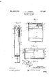
- Fig. 1 is a front elevation of a heat exchange device having a portion thereof broken away for the purpose of illustration; c Fig. 2 is a section taken on the line 2-2 of Fig. 1 on a slightly enlarged scale; 5c Fig. 3 is a section taken on the line 3 3 this arrangement compels this last mentioned of Fig. 1, the structure herein shown being alllso slightly enlarged over that shown in Fig.
- Fig. 4 is a perspective view of one end of a tank providing the humidier shown in Figs. 1, 2 and 3.
- the front wall 11 of the cas'- ing is of a length substantially less than the rear wall 12 thereof to provide an opening 13, the opening being provided to allow a1r to be introduced to the interior of the casing and be heated by the heat exchange device 14 located within the casing and adjacent lthe opening 13:
- the front wall 11 is provided with a plurality of openings 15 which are provided to allow the heated air contained within the casing to escape therefrom into the room to be heated.
- the casing generally designated 10 may have its upper end closed by a removable cap or cover plate 16 and this end of the casing directly below the cover plate may be provided with a plurality of openings 17. The purpose of these last mentioned openings 17 will be explained in the following:
- a water tank or humidifier 18' is arranged in the upper portion of the casing and is preferably located in spaced relation to the wall 10 ,of the casing to provide al passage 19v throughfwhich a. portion of the heated air may pass and be discharged from the casing through the opening 17. It is manifest that heated air to pass over the open end of the tank 18 and be humidified prior to its discharge through the opening 17 provided in the front wall of the casing.
- a wall such as. 20 of the tank 18 iscurved from'adjacent the Y Wall 10 to the front wall 11 and terminates near the upper end of the openings 15 provided in the wall 11.
- the wall 20 of the tank extends a suitable distance beyond the rim or upper edge of the tank, and therefore, when said tank is -in its fully elevated position, this extension 2() engages a stop 21 which stop extends from the wall 11 of the casing and will thus limit the upward movef ment of the tank and arrange the dele'cting wall 2O in proper relation to the openings 15.
- lt is evident that when the tank 18 is moved downwardly, a portion of its full extent of movement, that the wal-l 20 thereof is arranged with respect to the openings l5 so that these openings 15 are only partially closed which will control the amount oi heated air passing these openings.
- the casing generally designated 10 is furthe-r provided Awith the inwardly projecting ledges respectively designated 22 and 23, which are provided to engage the tank 18 and to cooperate therewith to completely stop the iiow of heated air from the casing. llt is evident that when the tank 18 is arranged in the dotted line position thereof shown in Fig. 2 that the upper termination of the curved wall 20 of the tank and the lower termination 24 thereof respectively engage the ledges 22 and 23 and thus will prevent the passage of air from the cas- 1n gt will benoted by reference to Fig.
- the tank 18 has its opposite ends provided with an endwise projecting arcuate flange 25 which respectively cooperates with the end walls 26 and 27 of the casing to revent heated air passing at this point, it eing understood that when the tank or receptacle 18 is' arranged in its fully lowered position, said anges cooperate with the ledges 22 and 23 and thus with the tank completely close the duct provided within the casing.
- Means is provided for controlling the movement of the receptacle or tank 18 and also guidin said tank during saidmovement.V
- any desira le structure may be employedfor this purpose, the particular means herein shown and described for accomplishing this last mentioned end includes a shaft 28 which Vextends from one end wall 26 to the other bined crank and handle 29 and is further provided with the sprockets 30 and 31 over 'which are respectively trained the chains or cables 32 and 33.
- Each of the cables is connected to one end of the tank, the opposite rare respectively secured to the end walls 26 and 27.
- rlhese tracks are preferably channelshaped to receive the anti-friction rollers such as 37 and 38 which are secured to the opposite ends of the tank and ride in the tracks and guide the tank during its movement within the casing 10.
- the-tank or receptacle 18 with its curved Wall 20 provides a combined deflector and humidiier for delecting heated air from the casing and huing, an element providin a humidifier, aA iwall thereof providing a e Hector, said element being supported for movement relatively to the casing across'the opening, vand providing means controlling 4the passage of air through said opening.
- a heat exchange device the combination of a casing having an opening through which heated air is discharged from the casing, an open tank providing a humidifier located in the casing, said tank being arranged in spaced relation to the walls ofthe casmg to permit heated air to pass between said casing, tank and across said tank and out throu h said opening, said tank being mounted or movement across the opening and providing an element of means preventing the escape of heated air through said opening.
- a heat exchange device the combination of a casing having'v an opening through which heated air is discharged from the casing, a tank located in the casing having a Lemos? VWall providing means for defleoting heated air through said opening, said tank being y movable relatively to the casing and opening, said casing having a ilange at one side of said opening with Which the tank engages to preyent passage of heated air through said openlng.
- a heat exchange device the combination of a casing having an opening through which heated air is discharged from said casing, an element providing a humidier, a deflector and a damper, said element being mov able transverse of the opening Within the casing.
- a heat exchange device the combination of a casing having an opening through which heated air is discharged from said casing, an element providing a humidier, said element being movable Within the casing across the opening and having a wall adapted' to be arranged relatively to said opening to vary the amount of airpassing through said opening, andlmeans with which said element is engageable to prevent the passage of air through said opening.
Landscapes
- Engineering & Computer Science (AREA)
- Physics & Mathematics (AREA)
- Thermal Sciences (AREA)
- Chemical & Material Sciences (AREA)
- Combustion & Propulsion (AREA)
- Mechanical Engineering (AREA)
- General Engineering & Computer Science (AREA)
- Air Humidification (AREA)
Description
Marchzg, 1932. M, WERMICH 1,851,027
HEAT EXCHANGE DEVICE Filed OCC. 23, 1929 Ma/4g y VM r /VQZZ Patented Mar. 29,- 1932 oFFica l OTTO M. WERMICH, CHICAGO, ILLINOIS, ASSIGNOR '1.0 MODINE MANUFACTURING COMPANY, 0F RACINE, WISCONSIN, A CORPORATION 0F WISCONSIN HEAT EXCHANGE DEVICE Application filed October 23, 1929. Serial No. 401,666.
struct the humidifier to provide a deflectory for deecting the heated air from the device into a room to be heated, the combined humid- Y ifier and deflector being capable of accom- )15 plishing regulation of the passage of heated air and, also preventing the discharge thereof from the device.
Another object of the invention is to arrange said humidifier relatively to the casgg@ ing in which the device is located so that a certain quantity of the heated air is directed over the humidifier prior to its discharge from the device and to combine a structure such as this with means whereby the circulation of air in ne the manner just referred to is prevented when said humidifier is arranged to prevent the escape of heated air from the device.
An additional object of the invention is to provide means for actuating the structure 3@ and to locate a certain element of said means outside of the casing for the device so that V said structure may be operated from the outside of the casing to accomplish the various above mentioned advantages.
The invention has these and other objects, all of which will be more readily understood when vread in conjunction with the accompanying drawings in which one embodiment of which the invention is'susceptible is disclosed, it being obvious that changes and modifications may be resorted to without departing from the spirit'of the appended claims forming a part hereof.
In the drawings, Fig. 1 is a front elevation of a heat exchange device having a portion thereof broken away for the purpose of illustration; c Fig. 2 is a section taken on the line 2-2 of Fig. 1 on a slightly enlarged scale; 5c Fig. 3 is a section taken on the line 3 3 this arrangement compels this last mentioned of Fig. 1, the structure herein shown being alllso slightly enlarged over that shown in Fig.
Fig. 4 is a perspective view of one end of a tank providing the humidier shown in Figs. 1, 2 and 3.
`1 he structure disclosed in the drawin s contemplates the use of a casing general y designated 1f). The front wall 11 of the cas'- ing is of a length substantially less than the rear wall 12 thereof to provide an opening 13, the opening being provided to allow a1r to be introduced to the interior of the casing and be heated by the heat exchange device 14 located within the casing and adjacent lthe opening 13: The front wall 11 is provided with a plurality of openings 15 which are provided to allow the heated air contained within the casing to escape therefrom into the room to be heated. The casing generally designated 10 may have its upper end closed by a removable cap or cover plate 16 and this end of the casing directly below the cover plate may be provided with a plurality of openings 17. The purpose of these last mentioned openings 17 will be explained in the following:
A water tank or humidifier 18'is arranged in the upper portion of the casing and is preferably located in spaced relation to the wall 10 ,of the casing to provide al passage 19v throughfwhich a. portion of the heated air may pass and be discharged from the casing through the opening 17. It is manifest that heated air to pass over the open end of the tank 18 and be humidified prior to its discharge through the opening 17 provided in the front wall of the casing. A wall such as. 20 of the tank 18 iscurved from'adjacent the Y Wall 10 to the front wall 11 and terminates near the upper end of the openings 15 provided in the wall 11. From this it can be seen that another portion of the heated air contained in the casing l0 is defiected from the casing and discharged out through the openings 15 provided in the casing. It is manifest that by virtue of the fact that this wall is in direct contact with the heated air, the water in the tank 18 will become heated and thus 100 To this kend, the tank 18 is mounted fon movement relatively to the casing and with respect to the openings 15 provided in the caslng.
llt will be noted that the wall 20 of the tank extends a suitable distance beyond the rim or upper edge of the tank, and therefore, when said tank is -in its fully elevated position, this extension 2() engages a stop 21 which stop extends from the wall 11 of the casing and will thus limit the upward movef ment of the tank and arrange the dele'cting wall 2O in proper relation to the openings 15. lt is evident that when the tank 18 is moved downwardly, a portion of its full extent of movement, that the wal-l 20 thereof is arranged with respect to the openings l5 so that these openings 15 are only partially closed which will control the amount oi heated air passing these openings. The casing generally designated 10 is furthe-r provided Awith the inwardly projecting ledges respectively designated 22 and 23, which are provided to engage the tank 18 and to cooperate therewith to completely stop the iiow of heated air from the casing. llt is evident that when the tank 18 is arranged in the dotted line position thereof shown in Fig. 2 that the upper termination of the curved wall 20 of the tank and the lower termination 24 thereof respectively engage the ledges 22 and 23 and thus will prevent the passage of air from the cas- 1n gt will benoted by reference to Fig. 4 that the tank 18 has its opposite ends provided with an endwise projecting arcuate flange 25 which respectively cooperates with the end walls 26 and 27 of the casing to revent heated air passing at this point, it eing understood that when the tank or receptacle 18 is' arranged in its fully lowered position, said anges cooperate with the ledges 22 and 23 and thus with the tank completely close the duct provided within the casing. Y
Means is provided for controlling the movement of the receptacle or tank 18 and also guidin said tank during saidmovement.V
Any desira le structure may be employedfor this purpose, the particular means herein shown and described for accomplishing this last mentioned end includes a shaft 28 which Vextends from one end wall 26 to the other bined crank and handle 29 and is further provided with the sprockets 30 and 31 over 'which are respectively trained the chains or cables 32 and 33. Each of the cables is connected to one end of the tank, the opposite rare respectively secured to the end walls 26 and 27. rlhese tracks are preferably channelshaped to receive the anti-friction rollers such as 37 and 38 which are secured to the opposite ends of the tank and ride in the tracks and guide the tank during its movement within the casing 10.
llt will benoted by reference to Fig. 3 that the curved flanges 25 provided upon the tank 18 as before stated, cooperate with the flanges 22-23 and thereby prevent the passage of heated air between the end walls of the tank and the end walls 26 and 27 of the casing, it being understood that these flanges 25 are apertured to allow thechains or cables 32 and 33 to be moved with relation to the tanks.
From the foregoing description of the structure, it is manifest that the-tank or receptacle 18 with its curved Wall 20 provides a combined deflector and humidiier for delecting heated air from the casing and huing, an element providin a humidifier, aA iwall thereof providing a e Hector, said element being supported for movement relatively to the casing across'the opening, vand providing means controlling 4the passage of air through said opening. v
2. In a heat exchange device, the combination of a casing having an opening through which heated air is discharged from the casing, an open tank providing a humidifier located in the casing, said tank being arranged in spaced relation to the walls ofthe casmg to permit heated air to pass between said casing, tank and across said tank and out throu h said opening, said tank being mounted or movement across the opening and providing an element of means preventing the escape of heated air through said opening.
3. ln a heat exchange device, the combination of a casing having'v an opening through which heated air is discharged from the casing, a tank located in the casing having a Lemos? VWall providing means for defleoting heated air through said opening, said tank being y movable relatively to the casing and opening, said casing having a ilange at one side of said opening with Which the tank engages to preyent passage of heated air through said openlng.
4. lin a heat exchange device, the combination of a casing having an opening through which heated air is discharged from said casing, an element providing a humidier, a deflector and a damper, said element being mov able transverse of the opening Within the casing.
5. In a heat exchange device, the combination of a casing having an opening through which heated air is discharged from said casing, an element providing a humidier, said element being movable Within the casing across the opening and having a wall adapted' to be arranged relatively to said opening to vary the amount of airpassing through said opening, andlmeans with which said element is engageable to prevent the passage of air through said opening. n 1n witness whereof, I hereunto subscribe my name this 21st day of October, A. D. 1929,
o* OTTO M. WERMICH.
Priority Applications (1)
| Application Number | Priority Date | Filing Date | Title |
|---|---|---|---|
| US401666A US1851027A (en) | 1929-10-23 | 1929-10-23 | Heat exchange device |
Applications Claiming Priority (1)
| Application Number | Priority Date | Filing Date | Title |
|---|---|---|---|
| US401666A US1851027A (en) | 1929-10-23 | 1929-10-23 | Heat exchange device |
Publications (1)
| Publication Number | Publication Date |
|---|---|
| US1851027A true US1851027A (en) | 1932-03-29 |
Family
ID=23588698
Family Applications (1)
| Application Number | Title | Priority Date | Filing Date |
|---|---|---|---|
| US401666A Expired - Lifetime US1851027A (en) | 1929-10-23 | 1929-10-23 | Heat exchange device |
Country Status (1)
| Country | Link |
|---|---|
| US (1) | US1851027A (en) |
Cited By (1)
| Publication number | Priority date | Publication date | Assignee | Title |
|---|---|---|---|---|
| US3137785A (en) * | 1959-11-13 | 1964-06-16 | Thermel Inc | Electric baseboard heater |
-
1929
- 1929-10-23 US US401666A patent/US1851027A/en not_active Expired - Lifetime
Cited By (1)
| Publication number | Priority date | Publication date | Assignee | Title |
|---|---|---|---|---|
| US3137785A (en) * | 1959-11-13 | 1964-06-16 | Thermel Inc | Electric baseboard heater |
Similar Documents
| Publication | Publication Date | Title |
|---|---|---|
| US3187744A (en) | Incubator | |
| US1872785A (en) | Heat exchange device | |
| US1950768A (en) | Unit heater and ventilator | |
| US4303007A (en) | Ceiling air outlet for air conditioning system | |
| US1924489A (en) | Ventilating apparatus | |
| US2442963A (en) | Air distributing unit | |
| US1851027A (en) | Heat exchange device | |
| US2022332A (en) | Air conditioning heating cabinet | |
| NO123203B (en) | ||
| US3958628A (en) | Vertical blower coil unit for heating and cooling | |
| US1889588A (en) | Unit heater and ventilator | |
| US2155070A (en) | Humidifier | |
| US2261579A (en) | Automobile heater | |
| US1063645A (en) | Hot-air register. | |
| US2555978A (en) | Air discharge register | |
| US1890521A (en) | Apparatus for heating rooms | |
| GB1455125A (en) | Room heaters | |
| US1687983A (en) | Hot-air furnace | |
| US600910A (en) | Heating device | |
| US1903134A (en) | Automobile heating system | |
| US2086076A (en) | Air mixing apparatus | |
| US2029368A (en) | Method and apparatus for conditioning air | |
| US2158332A (en) | Vehicle ventilating apparatus | |
| US1848537A (en) | modine | |
| US1869623A (en) | Electric heating apparatus |