US1851024A - Device for treating materials chemically - Google Patents
Device for treating materials chemically Download PDFInfo
- Publication number
- US1851024A US1851024A US181051A US18105127A US1851024A US 1851024 A US1851024 A US 1851024A US 181051 A US181051 A US 181051A US 18105127 A US18105127 A US 18105127A US 1851024 A US1851024 A US 1851024A
- Authority
- US
- United States
- Prior art keywords
- vessel
- jacket
- lugs
- treating materials
- materials chemically
- Prior art date
- Legal status (The legal status is an assumption and is not a legal conclusion. Google has not performed a legal analysis and makes no representation as to the accuracy of the status listed.)
- Expired - Lifetime
Links
- 239000000463 material Substances 0.000 title description 8
- 230000033001 locomotion Effects 0.000 description 11
- 239000012530 fluid Substances 0.000 description 2
- 239000002184 metal Substances 0.000 description 2
- 241000135164 Timea Species 0.000 description 1
- 230000008602 contraction Effects 0.000 description 1
- 239000012809 cooling fluid Substances 0.000 description 1
- 238000007599 discharging Methods 0.000 description 1
- 238000010438 heat treatment Methods 0.000 description 1
- 239000000126 substance Substances 0.000 description 1
- 238000005406 washing Methods 0.000 description 1
- 238000003466 welding Methods 0.000 description 1
Images
Classifications
-
- B—PERFORMING OPERATIONS; TRANSPORTING
- B65—CONVEYING; PACKING; STORING; HANDLING THIN OR FILAMENTARY MATERIAL
- B65D—CONTAINERS FOR STORAGE OR TRANSPORT OF ARTICLES OR MATERIALS, e.g. BAGS, BARRELS, BOTTLES, BOXES, CANS, CARTONS, CRATES, DRUMS, JARS, TANKS, HOPPERS, FORWARDING CONTAINERS; ACCESSORIES, CLOSURES, OR FITTINGS THEREFOR; PACKAGING ELEMENTS; PACKAGES
- B65D7/00—Containers having bodies formed by interconnecting or uniting two or more rigid, or substantially rigid, components made wholly or mainly of metal
- B65D7/12—Containers having bodies formed by interconnecting or uniting two or more rigid, or substantially rigid, components made wholly or mainly of metal characterised by wall construction or by connections between walls
- B65D7/22—Containers having bodies formed by interconnecting or uniting two or more rigid, or substantially rigid, components made wholly or mainly of metal characterised by wall construction or by connections between walls with double walls, e.g. double end walls
-
- B—PERFORMING OPERATIONS; TRANSPORTING
- B29—WORKING OF PLASTICS; WORKING OF SUBSTANCES IN A PLASTIC STATE IN GENERAL
- B29K—INDEXING SCHEME ASSOCIATED WITH SUBCLASSES B29B, B29C OR B29D, RELATING TO MOULDING MATERIALS OR TO MATERIALS FOR MOULDS, REINFORCEMENTS, FILLERS OR PREFORMED PARTS, e.g. INSERTS
- B29K2021/00—Use of unspecified rubbers as moulding material
Definitions
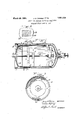
- the device will preferably be installed with its central axis vertical, so that the discharge pipe 6 and the discharge valve 7 will be at the bottom.
- the vessel 5 is provided with a stirrer having blades or paddles 8 attached to the central shaft 9 that is driven in anyconvenient manner and is supported upon bearings, one of which, as shown at 10, is located inside of the vessel 5 near one end thereof, while the other bearing 11 is located outside the vessel 5 at the other end thereof and may be provided with a stuiiing box ifrdesired to prevent leakage between the shaft 9 and the bearing 11.
- a jacket 12 surrounds the cylindrical surface of the vessel 5 and one end thereof as shown at 13.
- a stuffing box 14 is provided around the hole through the portion 13 through which the discharge pipe 6 passes.
- the inner vessel 5 is provided in the usual way with the inlets and outlets with proper valve connections by which material to be treated, such as used rubber for example, is introduced into the vessel 5 'and discharged therefrom after it has been treated, and also for introducing chemicals and washing iiuids into the vessel. 5 and discharging the saine therefrom at the proper time, and likewise inlet and outlet pipes with suitable valve connections are provided for the jacket 12 by means of which heating fluids and cooling fluids can be introduced into the space between the vessel and the acket at the proper time.
- These pipe connections and valves are old and well known in this art, and it is not i thought necessary to'illustrate or describe the same-as they ⁇ constitute no part of the presentV invention.
- the end of the jacket oppositethe end that extends around the inner vessel has been connectedto the vessel eitherby welding or riveting the end of the jacket to the outsidevwalls of the inner vessel, or Aby rigidly connecting the two in someother manner. Dueto the fact that the vessel andvjacket are frequently subjected to I' nectionfis made between the jacket and the inner vessel, land atthe same timea relative movement b'etweenthe vessel and ⁇ ja'cketFisv permitted without danger ofcausingleaks.'
- lLugs or projections 20 are provided on the outside offthe vessel 5 and lugs or proj ections 21are provided on the inside of the j
- lugs or vprojections are i jacket 12. shown in the illustrated embodiment of the invention as platesl tha-'tarev riveted to the vessel andjacket respectively.
- the plate'sv20 extend onlyv partially around the vessel 5, leaving suflicient spaces between themfor the plates 2l to pass, and the 'plates 21 on the jacket'12 are similarly disposed so that in installing tlieidevice, the vessel 5 can be lmo-ved j y into place longitudinallyfwithin the jacketl 12, ⁇ the plates 2O passing betweenvthe Vplates 21, after' which thevessel 5 can be turned ciri cumferentially until the lugs y20 arein line behind fthe lugs 21 withl their edges contacting, asfshown at 22,; The metal sheet 15 is then-riveted-in.place.
- a vessel In a device for treating materials, a vessel, a jacket for said vessel spaced therefrom, a fieXible closure extending across the space between said vessel and jacket and attached to each, and lugs on said vessel and jacket to stop the relative movement of said vessel with respect to said jacket at a predetermined relative position of the jacket and vessel.
- a vessel a jacket for said vessel spaced therefrom, a flexible closure extending across the space between said vessel and jacket and attached to each, lugs attached to said vessel and lugs attached to said jacket located between said first named lugs and said flexible closure.
- a vessel a jacket for said vessel spaced therefrom, a flexible closure extending across the space between said vessel and acket and attached to each, lugs attached to said vessel and lugs attached to said jacket located between said first named lugs and said ieXible closure, the lugs on said vessel being spaced from each other at least as far as the circumferential dimension of the other lugs.
- a vessel having closed ends, a jacket surrounding said vessel and spaced therefrom at one of said ends and disconnected therefrom at said end and between said ends, a flexible connection between the other of said ends and the jacket and permitting lengthwise movement of the vessel in the jacket, and cooperating elements on the vessel and jacket limiting said movement.
- a vessel having closed ends, a jacket surrounding said vessel and spaced therefrom at one of said ends and disconnected therefrom at said end and between said ends, a iieXible connection between the other of said ends and the jacket and permitting lengthwise movement of the vessel in the jacket, cooperating elements on the vessel and jacket limiting said movement, a pipe passing through said jacket and connected tothe first-named end, and a stuffing box surrounding said pipe to permit lengthwise movement thereof with said vessel.
- a vessel having closed ends, a jacket surrounding said vessel and spaced therefrom at one of said movement in a direction away from said firstenamed end.
Landscapes
- Engineering & Computer Science (AREA)
- Mechanical Engineering (AREA)
- Physical Or Chemical Processes And Apparatus (AREA)
Description
A Mm INVENTORS" BY v "M ATTORNEYSV fia Patented Mar. 29, 1932 ArEN'r oFFicE a l JAMES E. TRAINER, or BARBERTON, OHIO, AND WILLIAM a. JONES, or wEs'r Newy BRIGHTON, New YORK, Assienons 'ro THE BABcocx & wILc'ox coMrnNY, or
BAYONNE, NEW JERSEY, A CORPORATION yOCE `.'I'ERSIEY DEVICE FOR TREATING MATERIALS CHEMICALLY This invention relates to a device in which materials can be treated for the purpose of altering their characteristics, or otherwise changing the materials, and is especially applicable to devulcanizers for rubber. The invention will be understood from the description in connection with the accompany? ing drawings, in which Fig. 1 is a longitudinal section through the device; Fig. 2 is a side view partly broken away along the line 2-2 of Fig. 1 and Fig. 3 is an end view of the device partly in section. In the drawings reference character 5 indicates an inner vessel that is preferably made in the form of a cylinder with both ends closed. The device will preferably be installed with its central axis vertical, so that the discharge pipe 6 and the discharge valve 7 will be at the bottom. The vessel 5 is provided with a stirrer having blades or paddles 8 attached to the central shaft 9 that is driven in anyconvenient manner and is supported upon bearings, one of which, as shown at 10, is located inside of the vessel 5 near one end thereof, while the other bearing 11 is located outside the vessel 5 at the other end thereof and may be provided with a stuiiing box ifrdesired to prevent leakage between the shaft 9 and the bearing 11. A jacket 12 surrounds the cylindrical surface of the vessel 5 and one end thereof as shown at 13. A stuffing box 14 is provided around the hole through the portion 13 through which the discharge pipe 6 passes. The inner vessel 5 is provided in the usual way with the inlets and outlets with proper valve connections by which material to be treated, such as used rubber for example, is introduced into the vessel 5 'and discharged therefrom after it has been treated, and also for introducing chemicals and washing iiuids into the vessel. 5 and discharging the saine therefrom at the proper time, and likewise inlet and outlet pipes with suitable valve connections are provided for the jacket 12 by means of which heating fluids and cooling fluids can be introduced into the space between the vessel and the acket at the proper time. These pipe connections and valves are old and well known in this art, and it is not i thought necessary to'illustrate or describe the same-as they `constitute no part of the presentV invention. s Y In devices of this character, the end of the jacket oppositethe end that extends around the inner vessel has been connectedto the vessel eitherby welding or riveting the end of the jacket to the outsidevwalls of the inner vessel, or Aby rigidly connecting the two in someother manner. Dueto the fact that the vessel andvjacket are frequently subjected to I' nectionfis made between the jacket and the inner vessel, land atthe same timea relative movement b'etweenthe vessel and `ja'cketFisv permitted without danger ofcausingleaks.'
'Also provision is made for 'relieving excessive strains on the connections between the vessel and jacket,while permitting relative movement between `the two.- An annular, flexible sheet' metal strip 15, vU`shaped in cross ysec-2 tion, has one of itsfsides orv flanges riveted tothe outside-of thev vessel'5, as shown at 16, f
and its other side of flange riveted-to the inside ofthe jacketV 12 near. theend thereof,
as shown at 17, to provide a` gas tightseal fof* the space between the vessel and jacket which will permit relative motion ibetween the two, dueJ to expansion'and contraction. i
lLugs or projections 20 are provided on the outside offthe vessel 5 and lugs or proj ections 21are provided on the inside of the j These lugs or vprojections are i jacket 12. shown in the illustrated embodiment of the invention as platesl tha-'tarev riveted to the vessel andjacket respectively. The plate'sv20 extend onlyv partially around the vessel 5, leaving suflicient spaces between themfor the plates 2l to pass, and the 'plates 21 on the jacket'12 are similarly disposed so that in installing tlieidevice, the vessel 5 can be lmo-ved j y into place longitudinallyfwithin the jacketl 12, `the plates 2O passing betweenvthe Vplates 21, after' which thevessel 5 can be turned ciri cumferentially until the lugs y20 arein line behind fthe lugs 21 withl their edges contacting, asfshown at 22,; The metal sheet 15 is then-riveted-in.place. v s Y Y It will be seen that the unbalanced thrust due to fluids under pressure in the space o posite the end 13 will not be required to e taken up by the plate 15, but will be balanced by the pressure of the lugs or plates 20 on the vessel 5 bearing against the lugs or plates 21 on the jacket 12. At the same time the springiness or flexibility of the plate 15 will permit the vessel 5 and the jacket 12 to move relatively toeach other, either longitudinally as the discharge pipe 6 moves through the stuffing box 14, or radially as the sheet 15 will bend to accommodate these motions.
We claim: Y
l. In a device for treating materials, a vessel, a jacket for said vessel spaced therefrom, a fieXible closure extending across the space between said vessel and jacket and attached to each, and lugs on said vessel and jacket to stop the relative movement of said vessel with respect to said jacket at a predetermined relative position of the jacket and vessel.
2. In a device for treating materials, a vessel, a jacket for said vessel spaced therefrom, a flexible closure extending across the space between said vessel and jacket and attached to each, lugs attached to said vessel and lugs attached to said jacket located between said first named lugs and said flexible closure.
3. In a device for treating materials, a vessel, a jacket for said vessel spaced therefrom, a flexible closure extending across the space between said vessel and acket and attached to each, lugs attached to said vessel and lugs attached to said jacket located between said first named lugs and said ieXible closure, the lugs on said vessel being spaced from each other at least as far as the circumferential dimension of the other lugs.
4. In a device of the class described, a vessel having closed ends, a jacket surrounding said vessel and spaced therefrom at one of said ends and disconnected therefrom at said end and between said ends, a flexible connection between the other of said ends and the jacket and permitting lengthwise movement of the vessel in the jacket, and cooperating elements on the vessel and jacket limiting said movement.
5. In a device of the class described, a vessel having closed ends, a jacket surrounding said vessel and spaced therefrom at one of said ends and disconnected therefrom at said end and between said ends, a iieXible connection between the other of said ends and the jacket and permitting lengthwise movement of the vessel in the jacket, cooperating elements on the vessel and jacket limiting said movement, a pipe passing through said jacket and connected tothe first-named end, and a stuffing box surrounding said pipe to permit lengthwise movement thereof with said vessel.
6.V In a device of the class described, a vessel having closed ends, a jacket surrounding said vessel and spaced therefrom at one of said movement in a direction away from said firstenamed end.
J AMES E. TRAINER. WILLIAM A. JONES.
Priority Applications (1)
| Application Number | Priority Date | Filing Date | Title |
|---|---|---|---|
| US181051A US1851024A (en) | 1927-04-05 | 1927-04-05 | Device for treating materials chemically |
Applications Claiming Priority (1)
| Application Number | Priority Date | Filing Date | Title |
|---|---|---|---|
| US181051A US1851024A (en) | 1927-04-05 | 1927-04-05 | Device for treating materials chemically |
Publications (1)
| Publication Number | Publication Date |
|---|---|
| US1851024A true US1851024A (en) | 1932-03-29 |
Family
ID=22662701
Family Applications (1)
| Application Number | Title | Priority Date | Filing Date |
|---|---|---|---|
| US181051A Expired - Lifetime US1851024A (en) | 1927-04-05 | 1927-04-05 | Device for treating materials chemically |
Country Status (1)
| Country | Link |
|---|---|
| US (1) | US1851024A (en) |
Cited By (2)
| Publication number | Priority date | Publication date | Assignee | Title |
|---|---|---|---|---|
| US2858136A (en) * | 1954-02-23 | 1958-10-28 | Air Reduction | Transport container for liquefied gases |
| US5713483A (en) * | 1996-02-22 | 1998-02-03 | Naolco Chemical Corporation | Transportable brominator and a method for holding and transporting a product |
-
1927
- 1927-04-05 US US181051A patent/US1851024A/en not_active Expired - Lifetime
Cited By (2)
| Publication number | Priority date | Publication date | Assignee | Title |
|---|---|---|---|---|
| US2858136A (en) * | 1954-02-23 | 1958-10-28 | Air Reduction | Transport container for liquefied gases |
| US5713483A (en) * | 1996-02-22 | 1998-02-03 | Naolco Chemical Corporation | Transportable brominator and a method for holding and transporting a product |
Similar Documents
| Publication | Publication Date | Title |
|---|---|---|
| US1389768A (en) | Flanged coupling for double-pipe conduits | |
| US2841419A (en) | Flexible inner to outer pipe coupling with plural seals | |
| US1851024A (en) | Device for treating materials chemically | |
| US3684316A (en) | Rotary joint | |
| US1803665A (en) | Expansion joint or coupling | |
| US2008830A (en) | Sealing means | |
| US2113047A (en) | Rotary drier | |
| US2808657A (en) | Jacketed conical dryer | |
| US1606514A (en) | Universal | |
| US2969248A (en) | Shaft seal | |
| US872358A (en) | Pipe-joint. | |
| US3405760A (en) | Heat exchange apparatus and method of making same | |
| US3967674A (en) | Sealing structure for a machine for centrifugally casting pipes and machine including said structure | |
| US1539267A (en) | Heat-exchange apparatus | |
| US1515816A (en) | Stuffing box | |
| US543051A (en) | Island | |
| US2371166A (en) | Sealing means | |
| JPH06174113A (en) | Rotational distributor | |
| US1180806A (en) | Pipe-joint. | |
| US1531563A (en) | Pipe joint | |
| US826966A (en) | Cooler or condenser. | |
| US1737535A (en) | Universal joint | |
| US1181099A (en) | Steam-pipe joint. | |
| US1487248A (en) | Heat interchanger | |
| US1738619A (en) | Means for making fluid-tight joints around rotating shafts and the like |