US1851022A - Automatic regulator for pumping plants - Google Patents
Automatic regulator for pumping plants Download PDFInfo
- Publication number
- US1851022A US1851022A US318893A US31889328A US1851022A US 1851022 A US1851022 A US 1851022A US 318893 A US318893 A US 318893A US 31889328 A US31889328 A US 31889328A US 1851022 A US1851022 A US 1851022A
- Authority
- US
- United States
- Prior art keywords
- exhauster
- speed
- valve
- switch
- collecting main
- Prior art date
- Legal status (The legal status is an assumption and is not a legal conclusion. Google has not performed a legal analysis and makes no representation as to the accuracy of the status listed.)
- Expired - Lifetime
Links
Images

Classifications
-
- G—PHYSICS
- G05—CONTROLLING; REGULATING
- G05D—SYSTEMS FOR CONTROLLING OR REGULATING NON-ELECTRIC VARIABLES
- G05D16/00—Control of fluid pressure
- G05D16/20—Control of fluid pressure characterised by the use of electric means
- G05D16/2006—Control of fluid pressure characterised by the use of electric means with direct action of electric energy on controlling means
- G05D16/2066—Control of fluid pressure characterised by the use of electric means with direct action of electric energy on controlling means using controlling means acting on the pressure source
- G05D16/2073—Control of fluid pressure characterised by the use of electric means with direct action of electric energy on controlling means using controlling means acting on the pressure source with a plurality of pressure sources
Definitions
- This invention relates to certain new and useful improvements in gas and by-product coke oven plants and pertains to the means for automatically controlling the operation of such plants.
- the ovens are divided into batteries each of which has a collecting main which discharges through an associated crossover main into a suction main common 16 to all the batteries.
- the variation in the pressure within the collecting main is limited to one or two millimeters of water column by a valve placed in the crossover main which opens and closes upon the dictation of a collecting main governor responsive to pressure changes within the collecting main.
- This regulator may be of the type described in 20 Letters Patent Number 1,588,149, issued June 8, 1926.
- the collecting main regulator maintains the pressure of the collecting mai'nwithin very narrow limits but whenever conditions get such that it nears the limits of its efiec tiveness it calls for help from the exhauster control which corrects these conditions.
- the exhauster control consists primarily of a variable speed transmission interposed in the drive connection between the usual governor of the exhauster engine which may be;
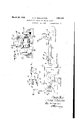
- Figure 1 is a diagrammatic view of a coke oven plant provided with my improved cont-rols
- Figure 2 is a schematic view of the electrical connections thereof and Figure 3 is a view of the variable speed transmission which is'interposed in the drive of the exhauster engine governor.
- 5 represents the collector main ofa battery ofovens, not shown, which is connected through a crossover main 3 with a suction main 7 to conduct the liberated gases within the collecting main to a cooler 8.
- suction ismaintained at the intake 9 of the cooler by an exhauster 10 connected with the cooler through a main 11.
- the exhauster 10 may be of any desired type, andin the present illustration, is a blower driven by an-engine l2 operated by steam or the like which is ledthereto through steam pipes 13, and its volume controlled by a fly ball governor 14.
- the fly ballgovernor is driven from the shaft of the blower by belts 16 and 17 drivingly connected through a variable speedtransmission 18.
- variable ratio speed transmission con sists-primaril'yof a low speed pulley 1-9 and a' high speed pulley 20 connected by agroup of friction drive cones or rollers (not shown) mounted within a housing 21.
- This transmission is a conventional device-and'its structure forms no part ofthis invention, a detailed description thereof will not-be given.
- a sprocketi22 is mounted adjacent the high speed pulley 20 and has asprocket chain 23 meshing therewith which is drive'nin one direction or the otherby a drive sprocket 2 4; fixed on the end of a shaft 25,-driven at areduced speed by a: motor 26. Movement of the sprocket 22 changes the relation of the cones within the housing 21 and changes the speed ratio between the pulleys 19 and 20; The motor 26 is-mounted'in a housing27 suitably supported from the base 28 of theidevice-and is actuated to run in one directionorthe other at the dictation of an automatic control mounted on apanel 29, the action of which is governed by a butterfly.
- valve- 30 of a motor 31 having a drive connection 32 with the valve whereby it is opened or closed by the motor, the operation of which is controlled by the action of a gasometer 33 connected, through a conduit 34, with the collector main 5so as to be directly responsive to pressure variations therein, light signals 35 being provided to indicate the positions and variations of the valve 30.
- the structure' above described constitutes the usual collector main governor and with this the exhauster governor is synchronized inthe following" manner
- the shaft 36 of the valve motor 31 has a liinit'switch 87 fixed thereto which is arranged to send impulses to theautomatic control panel 29 whenever the valve 30 reaches oneed e of its free Zone to drive the motor 26- of the variable ratio speed control, changing forcesthe exhauster to run faster or slower.
- the shaft 36 of motor 31 is provided with a limit'switch 37 which may consist ofan arm fixed to the shaft andmova'ble betweenswitch arms 38 and 39'nornially ar ranged to engage fixed contacts 40 having a common electrical connection il'which forms part of a cable 42 leading from the motor 31' to the control panel 29, and is connected with one S1Cle' l30fa switch 14 mounted on the panel" 29, through conductors 4'5, 46 and 47.-
- the shunt about the relay coil 53 beginning with the other contact 40 is through the switch arm 39, a conductor 60 also forming a part of the cable 42 which is connected with the second resistance unit 58 by suitable connections on the panel 29, through the unit 58 and then through the common conductors leading from the resistance units to the terminal 59 of the switch 44.
- the coils 52 and 53 are at all times part of a closed circuit, each having one end connected with the terminal 43 of the switch 44 by common conductors, including the conductor 47, part of the conductor 46 and conductors 61 and 62.
- the opposite sides of the coils are connected with the terminal 59of switch 44 through their respective resistance units 57 and 58 so that, as the shunt circuit is broken between the switch arm 38 and its associated contact 40 or between the switch arm 39 and its contact 40, the coil 52 or the coil 53 will become energized to close its respective switch, as will be readily apparent.
- the motor 63 drives a timing device 64 through a gear reduction 65, and the speed of the motor 63and thus the speed of the timing device is readily adjustable by a rheostat 66 mounted on the panel--29 and in series with the armature windings of the motor.
- the timing device 64 has a drum or contact ring 67, having a break in its circumference, mounted on its shaft and with which contactors 68 are slidably engageable as the drum begins to revolve, the contacts68 normally registering with the break in the peripherytil the timing device has completed a full cycle or until the break in the circumference of the drum 67 is again aligned with the contacts 68.
- the field of the motor 26 is connected across the lines at all times by being connected with the terminals 43 and- 59 of the switch 44 through conductors 71 and 72 forming a part of a cable 73 which connects the motor 26 with a manual control panel 74,'to be later described, and from where conductors 75 and .76, forming a part of a cable 77 connecting the manual controlpanel 74 with the automatic control panel 29, connect the same with the terminals '43 and 58 of the switch 44 through suitable connections on the panel 29 l r
- Thearmature ofthe motor 26, however, has its circuit closed, as before stated, by'the closing of either of the switches 54 or 55 and is maintained closed-only as long as the contacts 7'0 are electrically bridged so that the duration of operation of the motor 26 is readily controllable by adjusting the segments 69, the direction of rotation of the m0- tor depending upon which switch closes.
- the otherrside 82 of the armature is con-. nected by a conductor 83' with electrically connected contacts 84 of a limit switch 85 on the variable ratiotransmission shaft 25 which is driven at a reduced speedby-the' motor 26, passing through the normally closed switch to arm 86 and a conductor 87- to the control panel 74.
- the duration of operaflliOI'l-OffhGiIllOliOllQG depends upon-the set- V ting of the timing segments 69 which at maximum maintains the circuit closed .throughoutonly part of the cycle so that the major portion-of the cycle is devoted to a rest period for, the motor which permits :10 theexhauster control to leisurely change the speed :of theexhauster one step. If at that time .theva'lve 30 is still beyond the edge of its freemone, the cycle will be repeated and the ex'hauster speed lowered another T5 step.
- the limit switch has itsarm 89 secured to .the shaft.25 on which the sprocket 24 is fixed, so'that rotation thereof beyond a predetermined degree in either direction 535i opens the circuit of the motor 26 and thus prevent-sover-traveling.
- a light signal station 90 is connected with the control panel 29 by a cable 91 and has a red, a white and a green light whereby the operator is enabled toat all-times determine the operation and condition of'the entire system. ⁇ Vhen the valve 30 is within its freezone both the red and green lights are bright, but when the valve is too far closed and 'tl'lBGXhZlllStGI speed is being lowe-red the :red light dims out and the green remainsbright. Conversely, the green light dims and the red remains bright when the valve is too far open and thespeed of the exhauster is raised, the white light remaining bright as long as the systemis alive.
- Closing of the push button-switch 93 bridges the contacts 95to close the circuit of the armature of the motor 26 so t'hat' the direction of its current causes the motor 'toroperate'in a direction to raise the speed of the ex'hauster and closing of the push button switch 94 bridges the contacts 96 to close the'circuit of the armature of the motor 26 to lower the speedof the exhauster.
- the actual cycle of operation is as follows: Ju'stbeiorecharging an oven, the exhauster runs at that speed which holds the valve 30 at approximately thirty degrees open. The oven'is charged, thrown on the main and immediately the collecting main regulator valve opens to approximately degrees to accommodate this additional gas; Although the exhauster control immediately raises its speed one step, the action of the valve 30 is so rapidthat theeffect of the increased speed is not felt until after the valve has come to rest at about? 5 degrees open. The exhauster control then leisurely raises the speed two or three and sometimes four steps, gradually bringing the valve back to its thirty degree or approximate normal open position.
- a fluid pressure regulator for gas and coke oven plants the combination of a collecting main, an exhauster for drawing the gas from the collecting main, a control responsive to pressure variations within the collecting main for regulating the flow of gas from-the-collecting main and including a valve, a governor driven from the 6X-' hauster for regulating its speed, and means for adjusting the speed ratio between the governor andthe eXhauster, saidmeans being operable solely by the'action of the valve and remaining inactive as long as the valve remains within predetermined limits.
- a .fluid pressure regulator for gas and coke oven plants the combination of a collecting main, a governor for controlling the flow of, gas from the collecting main, an exhauster for drawing the gas from the collecting main, and means intermittently operable upon dictation of the collecting main governor for changing the speed of the exhauster in intermittent steps to co-ordinate itsspeed with the volume of gas coming from the collecting main.
- a fluid pressure regulator for gas A and coke oven plants the combination of a collecting main, an exhauster for drawinggas fromthe-collecting main, a control responsive to pressure Variations within the collecting,- main for regulating the flow of gas from the collecting main to the exhauster and including a valve, a governor driven from the exhauster for controlling its speed, and means responsive solely to the movement of the valve for adjusting the speed ratio between the governor and the exhauster.
- a fluid pressure regulator for gas and coke oven plants the combination of a collecting main, an exhauster for drawing gas from the collecting main, a control responsive to pressure variations within the collecting main and including a valve movable to regulate the flow of gas from the collecting main, a governor driven from the eXhauster for regulating its speed, and means operable upon movement of the valve beyond predetermined limits for adjusting the speed ratio between the governor and the exhauster to vary the speed of the exhauster whenever the pressure in the collecting main exceeds predetermined limits.
- a fluid pressure regulator for gas and coke oven plants the combination of a collecting main, an exhauster for drawing gas from the collecting main, a control responsive to pressure variations within the collecting main and including a valve movable to regulate the flow of gas from the collecting main, a governor driven from the exhauster for con trolling its speed, means for adjusting the speed ratio between the governor and the exhauster, and means intermittently operable upon movement of the valve beyond predetermined limits for actuating the adjusting means to vary the speed of the exhauster.
- a fluid pressure regulator for gas and I coke oven plants the combination of a collecting main, an exhauster for drawlng gas from the collecting main, a control responsive.
- a valve movable to regulate the fiow of gas from the collecting main a fly-ball governor driven from the exhauster for controlling the eXhauster speed, and means for adjusting the speed ratio between the fiy-ball governor and the exhauster in accordance with the movement of said valve toco-ordinate the speed of the exhauster with the volume of gas coming from the collecting main.
- a collecting main for controlling the flow of gas from the collecting main including a valve, an exhauster for drawing gas from the collecting main, and means intermittently operable to change the exhauster speed in intermittent steps as long as the valve remains beyond predetermined limits.
Landscapes
- Physics & Mathematics (AREA)
- Fluid Mechanics (AREA)
- General Physics & Mathematics (AREA)
- Engineering & Computer Science (AREA)
- Automation & Control Theory (AREA)
- Control Of Throttle Valves Provided In The Intake System Or In The Exhaust System (AREA)
Description
March 29,1932. w. M. SHALLCROSS 1,
' AUTOMATIC REGULATOR FOR PUMPING PLANTS Filed Nov. 12 1928 2 Sheets-Sheei l v k Ifd 3/ g I /6 COOL ER EXHA usrE/f March 1932- w. M. SHALLCROSS 1,
AUTOMATIC REGULATOR FOR PUMPING PLANTS Filed Nov. 12, 1928 2 Sheets-Sheet 2 Patented Mar. 29, 1932 UNITED STATES},
wnma M. sHALrcnoss, or MILWAUKEE, wrsoonsm, ASSIGNOR 'ro SHALLCROSS coN- TROL SYSTEMS COMPANY, or MILWAUKEE; WISCONSIN, A CORPORATION or WIS- CONSIN AuroMA'rIc aneumi'roa r03 PUMPING rnm rs Application filed 'Novem ber 12; 1928. Serial No. 318,893.
This invention relates to certain new and useful improvements in gas and by-product coke oven plants and pertains to the means for automatically controlling the operation of such plants. 7 In plants of this type, the ovens are divided into batteries each of which has a collecting main which discharges through an associated crossover main into a suction main common 16 to all the batteries. To insure a maximum degree of efficiency in the operation of a bat-- tery of ovens. the variation in the pressure within the collecting main is limited to one or two millimeters of water column by a valve placed in the crossover main which opens and closes upon the dictation of a collecting main governor responsive to pressure changes within the collecting main. This regulator may be of the type described in 20 Letters Patent Number 1,588,149, issued June 8, 1926.
From the suction ma1n,the gas'is carried through coolers to an exhauster mam lead ing to the intake of an exhaust-er which, to
trol system responsive to the pressure in the I suction main just ahead of'the coolers which has proven objectionable in that it is almost impossible to prevent hunting and seesawing between its control and that of the pressure regulator of the collector main, as this provided two independent regulators con-' 4' trolling the same gas line.
Furthermore, previous methods of regw I lating the exhauster speed to provide the desired suction attempted to change its speed for each small variation, and as an exhauster is an extremely heavy, cumbersome and slugretain the efficient functioning of the oven PATENT OFFICE I f gish piece of mechanism it always lagged be hind the condition it attempted to correct, doing more harm than good. I i
It is, therefore, an object of this inven-' tion to provide an exhauster speed control which does not set up hunting with the the provision of means for regulating the speed of an exhauster which functions only upon an excessive rise or fall of the rate of flow and thereby maintains the suction of the regulates the speedlof the exhauster in accordance with the. volume of gas liberated through the medium of a Variable speedcons trol governed directlyfrom the'valve' in the cross overmain and so arranged that the exhauster speed remains unchanged aslong as the valve is within a free zone and is changed whenever thefvalve reaches. either edge of thisyfree zone. This, in effect, ,isI
that the collecting main regulator maintains the pressure of the collecting mai'nwithin very narrow limits but whenever conditions get such that it nears the limits of its efiec tiveness it calls for help from the exhauster control which corrects these conditions.
The exhauster control consists primarily of a variable speed transmission interposed in the drive connection between the usual governor of the exhauster engine which may be;
' changethe speed ratio whenever the valve in the crossover main reaches either edge of its I free zone and, as the exhauster is'at all times under control of its fly ball governor, its speed is increasedor decreased, depending upon which edge of the free zone the valve has passed inthecrossovermain. I I
VVithythe above and other objects in view which will appear as the description proceeds,
my invention resides in the novel construction, combination and arrangement of'parts substantially as hereinafter described and more particularly defined the appended claims, it being understood that such changes in the precise embodiment of the hereindisclosed invention may be made as come within the scope of the claims.
In the accompanying drawings, I have illustrated one complete example of the physical embodiment of my invention constructed according to the best mode I have so far devised for the practical application of the principles thereof, and in which:
Figure 1 is a diagrammatic view of a coke oven plant provided with my improved cont-rols;
Figure 2 is a schematic view of the electrical connections thereof and Figure 3 is a view of the variable speed transmission which is'interposed in the drive of the exhauster engine governor.
Referring now more particularlyto the accompanying drawings inwhich like numer als designate like parts throughout the several views, 5 represents the collector main ofa battery ofovens, not shown, which is connected through a crossover main 3 with a suction main 7 to conduct the liberated gases within the collecting main to a cooler 8. A
, suction ismaintained at the intake 9 of the cooler by an exhauster 10 connected with the cooler through a main 11. The exhauster 10 may be of any desired type, andin the present illustration, is a blower driven by an-engine l2 operated by steam or the like which is ledthereto through steam pipes 13, and its volume controlled by a fly ball governor 14.
The fly ballgovernor is driven from the shaft of the blower by belts 16 and 17 drivingly connected through a variable speedtransmission 18.
The variable ratio speed transmission con sists-primaril'yof a low speed pulley 1-9 and a' high speed pulley 20 connected by agroup of friction drive cones or rollers (not shown) mounted within a housing 21. As this transmission is a conventional device-and'its structure forms no part ofthis invention, a detailed description thereof will not-be given.
A sprocketi22 is mounted adjacent the high speed pulley 20 and has asprocket chain 23 meshing therewith which is drive'nin one direction or the otherby a drive sprocket 2 4; fixed on the end of a shaft 25,-driven at areduced speed by a: motor 26. Movement of the sprocket 22 changes the relation of the cones within the housing 21 and changes the speed ratio between the pulleys 19 and 20; The motor 26 is-mounted'in a housing27 suitably supported from the base 28 of theidevice-and is actuated to run in one directionorthe other at the dictation of an automatic control mounted on apanel 29, the action of which is governed by a butterfly. valve- 30 of a motor 31 having a drive connection 32 with the valve whereby it is opened or closed by the motor, the operation of which is controlled by the action of a gasometer 33 connected, through a conduit 34, with the collector main 5so as to be directly responsive to pressure variations therein, light signals 35 being provided to indicate the positions and variations of the valve 30. The structure' above described constitutes the usual collector main governor and with this the exhauster governor is synchronized inthe following" manner The shaft 36 of the valve motor 31 has a liinit'switch 87 fixed thereto which is arranged to send impulses to theautomatic control panel 29 whenever the valve 30 reaches oneed e of its free Zone to drive the motor 26- of the variable ratio speed control, changing forcesthe exhauster to run faster or slower.
The operation and functioning of the control system-is entirely electrical and, therefore,reference is now direct-ed particularly to the schematic diagram illustratedin Figure 2 of the drawings, wherein all the C0I1I1'6C4 tions are depicted in detail, but for the sake of clearnessonly the majorones are referred to inthedescription.
As stated, the shaft 36 of motor 31 is provided with a limit'switch 37 which may consist ofan arm fixed to the shaft andmova'ble betweenswitch arms 38 and 39'nornially ar ranged to engage fixed contacts 40 having a common electrical connection il'which forms part of a cable 42 leading from the motor 31' to the control panel 29, and is connected with one S1Cle' l30fa switch 14 mounted on the panel" 29, through conductors 4'5, 46 and 47.-
The live terminals 48 and 49 of the switchpair of shunt circuits about the relay coils and 53 of magnetic switches oi and 55, respectively.
Fronione contact 40, the shunt'circuit'about the coil 52 is continued through theswitch arm 38, a conductor 56 which, as a part ofthe cable 42,- leads to' the control panel 29, where suitable conductors connect it with one-end of one of a pair of resistance un-it's 57 and 58; the adjacent-ends of which are connected, through the resistance unitand to the other terminal 59of the switch 4 L through connections, common-to bothunits, and thus to the other side of the line. The shunt about the relay coil 53 beginning with the other contact 40 is through the switch arm 39, a conductor 60 also forming a part of the cable 42 which is connected with the second resistance unit 58 by suitable connections on the panel 29, through the unit 58 and then through the common conductors leading from the resistance units to the terminal 59 of the switch 44.
The coils 52 and 53 are at all times part of a closed circuit, each having one end connected with the terminal 43 of the switch 44 by common conductors, including the conductor 47, part of the conductor 46 and conductors 61 and 62. The opposite sides of the coils are connected with the terminal 59of switch 44 through their respective resistance units 57 and 58 so that, as the shunt circuit is broken between the switch arm 38 and its associated contact 40 or between the switch arm 39 and its contact 40, the coil 52 or the coil 53 will become energized to close its respective switch, as will be readily apparent.
The position of the arm of the limit switch 37' with respect to the switch levers 38 and 39 is such that as long as valve 30 is within its free zone neither of the switch arms will be disengaged from its associated con-' tact, but whenever the valve travels beyond either edge of the free zone one or the other of the shunt circuits is broken to permit one of the relay coils to become energized and close its switch. Closing of either the switch 54 or'55 completes thecircuit of themotor 26 to drive the same in one direction or the other depending upon which switch is closed and also closes the circuit of a motor 63. The motor 63 drives a timing device 64 through a gear reduction 65, and the speed of the motor 63and thus the speed of the timing device is readily adjustable by a rheostat 66 mounted on the panel--29 and in series with the armature windings of the motor. I
The timing device 64 has a drum or contact ring 67, having a break in its circumference, mounted on its shaft and with which contactors 68 are slidably engageable as the drum begins to revolve, the contacts68 normally registering with the break in the peripherytil the timing device has completed a full cycle or until the break in the circumference of the drum 67 is again aligned with the contacts 68. f 7
Also mounted on the shaft of the timing device 64 is'a pair of electrically connected segments 69 which are individually adjustable on the shaft and with which contacts 70 are engageable throughout part of the revolution of the timing device, contacts 70 being in engagement with'the periphery of the segments 69 at the beginning and end of each cycle or one complete revolution of the timing devicewAs long as the contacts 70' are bridged by the electrically connected segments 69, or in other words, until oneof the contacts leaves its segment, the ClICllllS'Of the motor 26 is maintained closed.
The field of the motor 26 is connected across the lines at all times by being connected with the terminals 43 and- 59 of the switch 44 through conductors 71 and 72 forming a part of a cable 73 which connects the motor 26 with a manual control panel 74,'to be later described, and from where conductors 75 and .76, forming a part of a cable 77 connecting the manual controlpanel 74 with the automatic control panel 29, connect the same with the terminals '43 and 58 of the switch 44 through suitable connections on the panel 29 l r Thearmature ofthe motor 26, however, has its circuit closed, as before stated, by'the closing of either of the switches 54 or 55 and is maintained closed-only as long as the contacts 7'0 are electrically bridged so that the duration of operation of the motor 26 is readily controllable by adjusting the segments 69, the direction of rotation of the m0- tor depending upon which switch closes.
When the valve 30 is too far closed, having exceeded that edge of its free zone, the ex-- of the motor 26 so that its side 78 will be connected with the terminal 59 ofthe. switch 44 through a conductor 79 which is part of the cable 7 3to the manual control panel 74,
through suitable connections on the panel leaving the panel vthrough a conductor 80 which forms part of the cable 77 and then through a conductor 81 on the panel29 to one of the contacts 70, through the segments 69, one arm of the closed switch 55 and to the terminal 59. 1:
The otherrside 82 of the armature is con-. nected by a conductor 83' with electrically connected contacts 84 of a limit switch 85 on the variable ratiotransmission shaft 25 which is driven at a reduced speedby-the' motor 26, passing through the normally closed switch to arm 86 and a conductor 87- to the control panel 74. From the panel 74, the circuit continues through a conductor 88' which is a part of cable 77, to the panel 29-where suitable conductors lead to another arm of the switch 55, which, through: conductors 46 and 47, is connected with the terminal 43 of the switch 44 and thus completes the circuit of the armature .of the motor 26 to drive the same in thatv direction necessary'to adjust the variable speed'transmission to lower the exhauster speed a predetermined amount. 7
As before .stated, the duration of operaflliOI'l-OffhGiIllOliOllQG depends upon-the set- V ting of the timing segments 69 which at maximum maintains the circuit closed .throughoutonly part of the cycle so that the major portion-of the cycle is devoted to a rest period for, the motor which permits :10 theexhauster control to leisurely change the speed :of theexhauster one step. If at that time .theva'lve 30 is still beyond the edge of its freemone, the cycle will be repeated and the ex'hauster speed lowered another T5 step.
'5In 'theeventathe valve is opened too far and .thespeed-xofthe-exhauster is to be raised, the-shuntrcircuitabout the relay 52 is broken at th'eswitch arm 38 and the circuit'of the '20 armature ot' the motor 26 madeto-reverse the direction of current thereto which, as is well known, causes the'motor 26 to run in its opposite directiomchanging thespeed ratio of the variable transmission to cause the exhauster :to raise its speed. The operation of the'system during the raising of the exhauster speed issubstantially identical to that described inconnection with lowering it,:the ex hauster being raised in steps to accommodateithis sluggishness.
The limit switch has itsarm 89 secured to .the shaft.25 on which the sprocket 24 is fixed, so'that rotation thereof beyond a predetermined degree in either direction 535i opens the circuit of the motor 26 and thus prevent-sover-traveling.
A light signal station 90 is connected with the control panel 29 by a cable 91 and has a red, a white and a green light whereby the operator is enabled toat all-times determine the operation and condition of'the entire system. \Vhen the valve 30 is within its freezone both the red and green lights are bright, but when the valve is too far closed and 'tl'lBGXhZlllStGI speed is being lowe-red the :red light dims out and the green remainsbright. Conversely, the green light dims and the red remains bright when the valve is too far open and thespeed of the exhauster is raised, the white light remaining bright as long as the systemis alive.
.The'manual control panel 74: has a switch 92"=whic'h, as illustrated in full lines, connects the mechanism for automatic control and which, when thrown to its dotted line position, connects the-circuit for manual-control. hen arranged for manual control, the function of the switches 54-and 55 and the timing relay is replaced by a pair of push button 350? switches 98a'nd 94. Closing of the push button-switch 93 bridges the contacts 95to close the circuit of the armature of the motor 26 so t'hat' the direction of its current causes the motor 'toroperate'in a direction to raise the speed of the ex'hauster and closing of the push button switch 94 bridges the contacts 96 to close the'circuit of the armature of the motor 26 to lower the speedof the exhauster.
Summarizing the operation of the device, the actual cycle of operation is as follows: Ju'stbeiorecharging an oven, the exhauster runs at that speed which holds the valve 30 at approximately thirty degrees open. The oven'is charged, thrown on the main and immediately the collecting main regulator valve opens to approximately degrees to accommodate this additional gas; Although the exhauster control immediately raises its speed one step, the action of the valve 30 is so rapidthat theeffect of the increased speed is not felt until after the valve has come to rest at about? 5 degrees open. The exhauster control then leisurely raises the speed two or three and sometimes four steps, gradually bringing the valve back to its thirty degree or approximate normal open position. By this time, the temperature of the coal in the oven has raised considerably, and produces a relatively large volume of liberated gas, thus the exhauster stays at this higher speed, or it may even increase one more step as the gas yield from the oven approaches its maximum, until the'yield begins to decrease, when the exhauster will at intervals drop back step by step so that by the time of-the next charge it will have receded as many steps as it rose at the time of charge.
What I claim as my invention is:
1. In a fluid pressure regulator for gas and coke oven plants the combination of a collecting main, an exhauster for drawing the gas from the collecting main, a control responsive to pressure variations within the collecting main for regulating the flow of gas from-the-collecting main and including a valve, a governor driven from the 6X-' hauster for regulating its speed, and means for adjusting the speed ratio between the governor andthe eXhauster, saidmeans being operable solely by the'action of the valve and remaining inactive as long as the valve remains within predetermined limits.
2. In a .fluid pressure regulator for gas and coke oven plants the combination of a collecting main, a governor for controlling the flow of, gas from the collecting main, an exhauster for drawing the gas from the collecting main, and means intermittently operable upon dictation of the collecting main governor for changing the speed of the exhauster in intermittent steps to co-ordinate itsspeed with the volume of gas coming from the collecting main.
3. In a fluid pressure regulator for gas A and coke oven plants, the combination of a collecting main, an exhauster for drawinggas fromthe-collecting main, a control responsive to pressure Variations within the collecting,- main for regulating the flow of gas from the collecting main to the exhauster and including a valve, a governor driven from the exhauster for controlling its speed, and means responsive solely to the movement of the valve for adjusting the speed ratio between the governor and the exhauster.
4. In a fluid pressure regulator for gas and coke oven plants, the combination of a collecting main, an exhauster for drawing gas from the collecting main, a control responsive to pressure variations within the collecting main and including a valve movable to regulate the flow of gas from the collecting main, a governor driven from the eXhauster for regulating its speed, and means operable upon movement of the valve beyond predetermined limits for adjusting the speed ratio between the governor and the exhauster to vary the speed of the exhauster whenever the pressure in the collecting main exceeds predetermined limits.
5. In a fluid pressure regulator for gas and coke oven plants, the combination of a collecting main, an exhauster for drawing gas from the collecting main, a control responsive to pressure variations within the collecting main and including a valve movable to regulate the flow of gas from the collecting main, a governor driven from the exhauster for con trolling its speed, means for adjusting the speed ratio between the governor and the exhauster, and means intermittently operable upon movement of the valve beyond predetermined limits for actuating the adjusting means to vary the speed of the exhauster.
6. In a fluid pressure regulator for gas and I coke oven plants, the combination of a collecting main, an exhauster for drawlng gas from the collecting main, a control responsive.
to pressure variations within the collecting main and including a valve movable to regulate the fiow of gas from the collecting main, a fly-ball governor driven from the exhauster for controlling the eXhauster speed, and means for adjusting the speed ratio between the fiy-ball governor and the exhauster in accordance with the movement of said valve toco-ordinate the speed of the exhauster with the volume of gas coming from the collecting main.
7 In a fluid pressure regulator for gas and coke oven plants, the combination of a collecting main, a collecting main governor for controlling the flow of gas from the collecting main including a valve, an exhauster for drawing gas from the collecting main, and means intermittently operable to change the exhauster speed in intermittent steps as long as the valve remains beyond predetermined limits.
In testimony whereof I have hereunto affixed my signature; 7
WILMER M. SHALLOROSS.
Priority Applications (1)
| Application Number | Priority Date | Filing Date | Title |
|---|---|---|---|
| US318893A US1851022A (en) | 1928-11-12 | 1928-11-12 | Automatic regulator for pumping plants |
Applications Claiming Priority (1)
| Application Number | Priority Date | Filing Date | Title |
|---|---|---|---|
| US318893A US1851022A (en) | 1928-11-12 | 1928-11-12 | Automatic regulator for pumping plants |
Publications (1)
| Publication Number | Publication Date |
|---|---|
| US1851022A true US1851022A (en) | 1932-03-29 |
Family
ID=23240007
Family Applications (1)
| Application Number | Title | Priority Date | Filing Date |
|---|---|---|---|
| US318893A Expired - Lifetime US1851022A (en) | 1928-11-12 | 1928-11-12 | Automatic regulator for pumping plants |
Country Status (1)
| Country | Link |
|---|---|
| US (1) | US1851022A (en) |
-
1928
- 1928-11-12 US US318893A patent/US1851022A/en not_active Expired - Lifetime
Similar Documents
| Publication | Publication Date | Title |
|---|---|---|
| US2185786A (en) | Means for regulating electric steam generators | |
| CN103277871A (en) | Speed control device of outdoor draught fan of air conditioner | |
| US1851022A (en) | Automatic regulator for pumping plants | |
| US1816174A (en) | Blast furnace control system | |
| US1670313A (en) | System of fluid-pressure regulation | |
| US2226510A (en) | Air conditioning system | |
| US2482496A (en) | Sequential control for electric motors | |
| US2039426A (en) | Apparatus for controlling prime movers | |
| US2050020A (en) | Method of and apparatus for remote pressure control in fluid distribution systems | |
| US2006631A (en) | Means for regulating electric steam generators | |
| US1921172A (en) | Average temperature control mechanism for heating systems | |
| US4180249A (en) | Installation for controlling pressure of gas under shaft top in super-capacity blast furnace | |
| US2105686A (en) | Combustion control system | |
| US3556678A (en) | Method and apparatus for low frequency synchronous starting of reversible pump turbines | |
| US2129526A (en) | Control system and apparatus for heating | |
| US414191A (en) | Electrical regulating apparatus | |
| US2732289A (en) | Goeke | |
| US1670070A (en) | Power installation | |
| US2145117A (en) | Speed-governing mechanism | |
| US1810627A (en) | Constant speed control for prime movers | |
| US1424042A (en) | Automatic regulator for coke ovens | |
| US1674610A (en) | Power installation | |
| ES446425A1 (en) | Apparatus for controlling the gas pressure under the shaft top in a blast furnace | |
| US1725202A (en) | Electrical controller for conveying systems | |
| US1450620A (en) | System for regulating frequency |