US1851005A - Tape-applying machine - Google Patents
Tape-applying machine Download PDFInfo
- Publication number
- US1851005A US1851005A US143986A US14398626A US1851005A US 1851005 A US1851005 A US 1851005A US 143986 A US143986 A US 143986A US 14398626 A US14398626 A US 14398626A US 1851005 A US1851005 A US 1851005A
- Authority
- US
- United States
- Prior art keywords
- tape
- work
- feeding
- machine
- members
- Prior art date
- Legal status (The legal status is an assumption and is not a legal conclusion. Google has not performed a legal analysis and makes no representation as to the accuracy of the status listed.)
- Expired - Lifetime
Links
Images
Classifications
-
- A—HUMAN NECESSITIES
- A43—FOOTWEAR
- A43D—MACHINES, TOOLS, EQUIPMENT OR METHODS FOR MANUFACTURING OR REPAIRING FOOTWEAR
- A43D43/00—Machines for making stitch lips, or other preparatory treatment of soles or insoles before fixing same
- A43D43/06—Machines for making stitch lips, or other preparatory treatment of soles or insoles before fixing same for applying reinforcing materials to insoles; Attachment of ornamental tapes or ribs, e.g. sewing ribs, on soles, or the like
Definitions
- This invention relates to a 1 machine for applying tape for reenforcing shoe parts and similar work in which a tapecoated with adhesive is delivered to and pressed upon the 5 work as it is fed through the machine.
- the principal object of the invention is the provision of a simple,” compact and em:
- Another-objectof theinvention is the pro p vision of feeding means adapted for feeding the tape directly from a source of tape supply without the intervention of pulling off means. In attaining this object the cooperating.
- feeding members are provided with feeding faces adapted to engage andto grip the tape its entire width with uniform pressure
- the feeding-faces of the-feeding members are preferably of'dimensions suit able for tapes of the greatest width employed 1 in this character'of work. Unless the tape 18 gripped its entire width with a uniform pres sure during the feeding movement there is a tendency for the tape to stretch in the parts not gripped and to wrinkle whenpressed upon the work and in some cases tofpull off after the pressing'operation. lVhen cover ing the entire width-of the tape the feeding means will lay it'on the work smoothly and 0 will, to some extent at'least,'serve to press it 7 intoadhesive contact with the work.
- A' further object oftheinvention- is the provision of-mea-ns for severing the-'tapeat Z
- l'prof a Vide a pair of co-operating members for cut ting the tape at the-willjof the operator and without interfering the operation of'the machine.
- These Amembers are preferably. in j the form of shearing members pivotallycon' 'necte'd together and operating in the same manner as scissors or shears and are normally ward into acuttin-g positionto cut by treadles by thismanner' of cutting are seriousdisad-f;
- the two shearing members are mounted on asuitable carrier above the work-support of the machine to avoid interference with the free handling of the work and are moved longitudinally into operative position; means being provided for opening and closing said members to cut on the forward movement, for guiding the cutting ends of the members to cut on one side or the other of the work and for raising the upper feeding and pressing members to permit the entrance of the shearing members at the desired point of cutting.
- a cutting device of this character has a marked advantage in that it is possible to guide the shearing members in their forward movement to the exact point at which the cutting vof the tape should be effected to secure the best results;
- the upper feeding andpressing members are raised in the forward movement of the cutting members the work is lifted up from the work-support and the points of the cutting members are directed to cutthe tape close to the face of the work thereby obviating any loose end.
- the cutting may be effected at a point close to the pressing means and beyond the feeding means thereby leaving the supply end of the tape in a position to be gripped by the feeding means when those parts are returned to normal feeding position on the return stroke of the cutting members. The cutting operation may thus be accomplished without stopping the machine since the movement of the upper feeding member when raised is ineffective to feed the tape.
- Another object of the invention is the pro vision of simple and efficient means for applying heat to tapes which are coated. with adhesives susceptible to being softened or rendered tacky by heat.
- I provide a simple electric heating device mounted on the top of the machineover which the tape may be drawn before passing to the feeding means.
- the tape may be drawn before passing to the feeding means.
- the cover may be raised or opened up to remove the tape from contact with the heating surface without necessitating the turning ofi of the electric current.
- the cover may also be adjusted in any desired position in relation to' the heating surface and thereby the heat ing effect on the tape may be regulated while the machine is inoperation- It is possible, therefore, to control to a fine degree the tackiness of the tape and to deliver it to the feeding means in justthe right condition for securin the best results and all danger of burning or injuring the tape is eliminated.
- Another object is the provision of a tape guide which may be easily removed to permit the substitution of guides of other dimensions for tapes of different widths.
- the tape guide located adjacent the feeding means should be provided with a guiding passage corresponding in width to the width of the tape being used. If the guiding passage is wider than the tape, it permits of lateral play of the tape in its forward movement which will prevent the tape being laid in a straight line. Since tapes of different widths are used for 'difierent classes of work,"I provide a tape guide which is easily removable to permit the installation of a guide having a guiding passage corresponding to the width of the particular tape being used.
- An additional object is the provision of means for guiding the work comprising an edge-gage adjustable transversely the work and mounted beneath the work-support and adapted to be depressed to an inoperative position at the will of the operator.
- I provide a gage mounted below the work-support and adapted to be moved vertically into an operative position projecting through and above the work-support or into an inoperative position below it.
- the gage comprises an upright member jcarricd by an arm pivotally mounted underneath the work-support and adapted to be thrown from an inoperative to an operative position or vice versa by a finger piece on the front of the machine and within easy reach of the operators hand while holding the work.
- Suitable means yieldable to a sli htpressureis pro vided for holding the gage in one position or the other.
- gage is of special advantage for that class of work having holes or openings because thework may be first placed in the machine for laying tape around the edge of the opening and the gage then thrown up into the hole and depressed when the hole is finished.
- Fig. 9 is 9 .Referring to the drawings,the frame machines heretofore in use, the gages inter-J specifically set forthland described hereinafter.
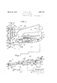
- Figure 1 is a side elevation as viewed from the op'erators seat of the-operative end of'a machine constructed and operated in accordance with my nvention;
- Fig. 2 is an end elevation of the same looking from left to right .in Fig. 1;
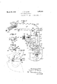
- Fig. 3 is alongitudinalsectional view of a heating element mounted on themachine for renderingthe tape tacky ,
- Fig. 4 is a plan view of the lower arm and cutting mechanism with the upper arm removed;
- Fig. 5 is a rear elevation of the cutting mechanism and endof the upw friction.
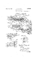
- Fig. 7 is a-bottom plan view of the gage mechanism
- Fig. Sis a view in'perspective of the removable guide for delivering the tape perspective view from below of the pressing member
- Fi 10 is a diagrammatic viewillustrating the position of a sampleof work in broken lines at the beginning of the taping operation andthe positionof-the same work in full lines at the conclusion of the taping operation withv the cutting mechanism in shearing position
- Fig. 11 is viewin perspective, partly insection of the guide mem-- ber carried by the cutting members foirdi recting said members in their longitudinal movement
- the work-support20 is in the'jformof a
- the end ofrthe bracket is split and provided with ears 38' bored to receive a screw 39 for fastening the bracket to the end of a -rockshaft 40 rotatably mounted in the upper arm 16-.
- the feeding faces of both the feeding member and the idler are-of a width correwithout distortion.
- r A forward and backward movement. is imparted to the feed foot by-rocking therock ings but which are'the same as those shown ferred' to.” For lowering the feed foot to grip the work at the beginning of the feedmovement, aliftshaftoO (Fig.
- feeding 100 byla screw 42 takes up any end thrust off said shaft.
- feeding r top end of the feed bar 35 by a screw 53 and carries a screw pin 5e upon which is loosely mounted a squared block 55 loosely riding in the yoked upper end 56 of a link 57'which at its lower end is pivotally connected by a screw pin 58 to an arm 59 carried by a collar 60 secured to the end of the lift shaft.
- the rocking of the lift shaft raises and lowers the link and the link in its reciprocating movements carries the feed bar with it through the instrumentality of the block and collar.
- a spring 62 is interposed between the upper end of the feed bar and a hood 63 fixed to the link by a screw 64:.
- the top end of the feed bar is recessed for receiving the lower end of the spring to prevent lateral displacement thereof.
- a fibre washer 65 mounted on the'feed bar between the collar 52 and the upper end of the housing 36 prevents wear on'the parts.
- the feed foot is given a four-motion movement. Normally the feed foot is in a raised position at the starting point but the parts are so timed that upon the starting of the machine the feed foot is lowered to grip the work by the oscillation of the lift shaft and then the oscillation of the rock-shaft turns the housing and the feed bar to move the feed foot in a forward direction carrying the work with it.
- the oscillation of the lift shaft causes the feed foot to be raised and to continue in a raised position during the return movement of the feed foot when the lift shaft then oscillates in the other direction permitting the feedfoot to descend and grip the work for another feeding movement;
- the guide 23 is secured to the feed-bar by the screw 33.
- the guide may be made of two thin plates partially secured together to form a fin 7 0 and then bent outwardly on an oblique line and turnedaround to form a guideway or passage 71 for the tape.
- the fin portion is adapted to fit a vertical recess in the feed-bar and is bored at 72 to receive the screw 83 for securing the guide to the feed-bar.
- the lower end of the passage 71 is adjacent'to the curved rear end of the feeding member 21 and the rear wall of the guide extendsdown wardly beyond the front and'side walls of the passage to form a guiding extension 73 for directing the tape in between the feeding member and the idler (Fig. 2)
- the passage 71 should correspond in widthto the width of the tape being used in order to avoid any lateral play of the tape when drawn through the passage and thereby to insure its accurate positioning between the feedingmembers.
- any suitable means may be provided for preventing retrograde movement of the tape through the guide and one form of such means is shown comprising a weighted dog 74 loosely mounted on a pin 75 carried by cars 7 6 formed on the top rear portion of the guide 23.
- the tape engaging edge of the dog is inclined downwardly and is serrated or toothed and the dog is so disposed in the guide that gravity acting on the weight tends to hold its serrated edge in engagement with the tape.
- the tape In its movement downwardly thetape slides freely by the dog but as soon as it is drawn upwardly the serrated edge penetrates the tape and holds its firmly against upward movement.
- Fig. 2 the dog is shown in normal position but in Fig. 8 the weighted portion of the dog is shown raised to permit the tape to be drawn upwardly.
- the guide 23 is designed for oneparticular width of tape, it is necessary, when a different width of tape is about to be used in-the machine, to change the guide. This is a very simple operation necessitating the manipulation of the screw 33 only. By loosening this screw the guide may be withdrawn from the recess in the feed-bar and another guide. having a passage of a width corre sponding to the width of the tape about to be used, may be inserted and the screw tightened.
- the pressing member or'hammer 24 is fastened at one end by a screw to the lower end of an upright arm 81 fixed on the end of a shaft 82 mounted for rocking movement in the end of the upper arm 16.
- a pin 83 locks the hammer and arm together against relativemovement.
- the free end 84 of the hammer is turned laterally outward and its lower face 85 serves as a pressing surfacefor engaging the work, the hammer being so mounted that its pressing surface is just in advance of the feeding members.
- the pressing surface may be provided with a plurality of shallow grooves 86, preferably arranged in two parallel series at right angles to each other.
- the laterally turned end 84 of. the hammer has an arm or extension 87 provided with a depending pin 88. The arm is of such length that the pin is positioned behind the feeding members and presses downwardly upon the work when it is first placed in the machine and holds it against twisting until it is gripped by the feeding and the pressing members.
- a short arm or lug 90 is fixed on the collar 60 in position to engage the end of a screw 91 threaded throughthe lower portion of the upright arm 81 and held therein 'inadjusted position'by a set nut 92 (Fig.2).
- a spring '98 under compression bears at one end against the 'arm 81' and at the other endagainstan adjusting screw 94 threadcd th'rough'the bent over end of a bracket 95 formed on theup'per-arm of the machine.
- a set nut 97 retains the screw 94 in adjusted position.
- the-tapeytheftwo shearing members 25 and 26 are arranged for longitudinal movement into and out of operative cutting-position with means for effecting the cut ting ator near the end of their forward move ment; Any suitable means may be provided for'mou'ntmg and operatingsaid members and one form'of such means lsshown comprlsing the following.
- a carrier block 100 is mounted for sliding movement onthe rock-shaft lO and lift-shaft 50, these two shafts being parallel and'lying in the same horizontal plane, and the bottom face of the block is recessed to receive the end of the shearing ;member 25 which'is loosely secured thereto by a screw 101 with a spring 102interposed on theshank of the screw betweenthe end ofrthe shearing member and the head of the screw.
- the spring 102 should be suh'iciently -stiff to hold the end of the shearing member in flat engagement with thebottom face of the block and yet permit of a slight yielding when the forward end of the shearing memberis depressed.
- the end of the member 25 fits snugly into the re cess in the bottom face of the block to prevent lateral movement thereof, since this member has a longitudinal movement with. the block
- the arm maybe recessed at 96 is' released, the spring 105 ing against the screw 117.
- a bell-crank lever 106 is pivotaliy mounted on a pin 107 set in the upper arm and one arm of saidleveris provided with a laterally extending pin 108 carrying a roll 109 in position to engage the rearface of the block 100 and the other arm of the said lever is attached'by a cord or chain to a treadle (not shown). Then the treadle is pressed 7 down the block and shearing'members are thrown forward through the in'strumentality of the bell-crank lever and when the pressure forces the blockback to normalposition.
- 'a cam plate 110 is loosely mounted on the extended rear end of the hammer shaft 82, that portion of the cam plate beingin the form of a sleeve to receivetheshaft.
- the shearing members are mounted a sufficient distance above the worksupport and lower arm to afford full clearance space therefor.
- a block 120 (Fig...11) is mounted upon the upper end of the pivot pin- 103 and providedwith a, vertical, open at the, top, recess 121" 7 within which is rotatably mounted aroll 122 V on a'pin 123 set in the block transversely'the recess.
- a dependingvertical cam plate125 is fastened to the under face ofthe upperarm" in position for its lower edge 126 to'engage thero'll 122 in the block 120.
- Fig. 4 is illustrated in plan three positions of the shearing members. The full lines show the normal inoperative position, the broken lines, the open position of the members preparatory for cutting just before the end of the forward stroke and the dotted lines the closed position at the end of the forward stroke, the cutting having been accomplished.
- the arm 114 For raising the upper feeding member and the hammer or pressing member on the forward stroke of the shearing members, the arm 114 is fasten-ed to the shaft 82 for rocking it.
- the lower end of the shaft and the arm is centrally split for a short distance from said bore so'that when the screw 130, threaded through the inner half of said arm, is tightened, it compresses said bore around said shaft to hold the arm firmly locked thereto.
- the upper end of the arm carries a roll 131 on a screw 132 set endwise in said arm, which roll is adapted to be engaged by a forwardly extending cam-plate 133 secured to the top face of the block 100 by screws 134.
- the edge 135 of said cam-plate (Fig.
- edge-gage 28 is mounted below the work-support in a manner which permits it to be depressed below the top surface thereof whenever required and without any appreciable effort on the part of the operator.
- Any suitable means for attaining this end may be employed and one such is shown comprising an arm 140 having one end in the form of a transverse collar 141 to permit it to be mounted on and secured by a screw 142 to a pin 143 rotatably mounted at one end in a bracket 144 fastened by a screw 145 to the under face of the work-support and atthe other end in the side wall 146 of the end of the lower arm 15, (Fig. 7 A spring 147 on the pin 143 holds the arm in engagement with the bracket 144 and against lateral movement on said pin.
- a slide 148 Slidably mounted on the top face of said arm 140 is a slide 148 which carries at one end the gage 28.
- a depending screw 150 which extends downwardly through a longitudinal slot 151 in the arm and is adapted to receive a knurled headed binding nut 152 which when tightened overlaps the slot 151 and holds the slide in. adjusted position on the arm.
- the work-support is provided with a slot 154 through which'the gage projects when in operative position, said slot being su'l'liciently long to permit a wide adjustment of the gage at diiferent distances from the feeding means in a line perpendicular to the normal line of feed.
- the gage may be moved from an operative to an inoperative position or vice versa by turning the pin 143 and for this purpose a finger-piece 156 is fastened on the end of the pin which projects beyond the side wall 146 of the lower arm of the machine.
- the finger-piece is so located as to be within easy reach of the right hand of the operator when handling and guiding the work through the machine and its manipulationrequires no appreciable effort nor does it interfere with the work.
- Fig. 3 the gage is shown in an operative position extending above the worksupport and in Fig. 6 it is shown in an inoperative position, the top of the gage being just below the top face of the work-support.
- the end wall 157 of the lower arm is cut away at 158 to receive the gage end of the slide which limits the downward movement of the arm 140.
- A. spring 160 is mounted on a screw 161 set in the edge of the arm, one end of the spring being locked in a hole 162 in the arm and the other end bearing against the end wall 157.
- the lower end of the spring is bent to forman angle for receiving the lower inner corner edge of said end wall when the arm is down so as to lock it in that position. Only a slight pressure is required, however, to move the gage from one position to the other.
- the binding nut is loosened, then used for moving the slide 148 to the desired positionandfinally tightened, an operation which requires but a moment of time.
- a gagev ofthis character is most advantageous in .view of the varied character of work being done in shoe factories at the present time, much. of which requires a gage. intermittently rather than constantly. This is especially true of work having edge projections such as straps andbands and hav ing cut out portions and the speed atwhich the work may be turned out is materially increased if the gage may be dropped down out. of the way when necessary, if only momentarily.
- the machine is adapted for using and applying all kinds of adhesively coated tapes longitudinal bore 172 to receive the-heating coil which consists oftheordinary cylindrical casing designated as170 with an interior wire coil 173 and a filler material 174.
- Theelectric conductors 17 5 are covered with insulating material 176 and a spiral spring 177 protects the conductorsfrom strain: ad-
- alight-angled slide lock 180 (Fig. 12)is slottedat 181 and-mounted on a screw 182 set inthe under face of an overhanging end portion 183 of the casing 171;
- the lock 180 being loosely mounted on the screw 182 is capable of a limited sliding movement in a direction transverse to the bore 172 and when the heating coil is'placed in said bore the lock maybe pushed inwardly to cause its portion 184 to enter between two adjacent spirals of the protective spring 177 to hold the same. This relieves the heating coil from all strain or pull which may happen to be exerted on the conductor cable The coil maybe released by pulling the slide lock out of engagement with the spring 177.
- the casing 171 may be attached to-any' suitable part of the machinebntispreferably secured above the end ofthe upper arm to the two arms of a split bracket 186 by screws 187 threaded in bottom lugs 188 on the casing; the bracket being fastened to the top of theupper arm by screws 189; v
- the casing 171 is preferably located directly above the feeding means with itsdelivery endin position to deliver the tape in an approximately vertical line to the tape One form of such means is shown.
- the tape passes along the top ofthe casin which is a 'roximatel horizontal the top and end are provided with a. grooved run-way 1.95 in which the tape :travels.
- the cover is frictionally hinged so that it will remain in any positionlto which it is moved and'is provided near its free end with a dependingloop 200 through .WlllCllftllQ tape passes, the casing being recessed at 201. to receive. the lower end of the loop when the cover is closed.
- the position of the tape in relation to the heater is controlled by the cover so that when the cover is raised the tape is carried up with I itand away from the heated surface. ,This is an important consideration in the use of heating devices of this characte-rbecause it enables the operator to control absolutely the degree to which the tapeis heated.
- a weighted dog 206 of a'construction similar to the dog7t carried by the tape guide i's-mounted'on a pin 207 set transversely in" the ears 208 ofthe delivery end of the casingl71 to prevent retracti've movementof the tape andbelow the dog is a roll 209' for I v holdingthe tape in the groove at that point.
- the tape 36 may be extended outwardly' to engage the tape (Fig. 2) between the casing-171 and tape guide and to flatten it out for smooth deliveryto the tape guide: p
- the tape is. threaded from the source of supply through the tape guide and the end is pushed under the upper feeding member which is The hood63 carried by the feed-bar housing normally in 'a raised positionwhen the ma- 7 chine is at rest.
- the tape used isof the kind requiring heat, it is laid in the groove on the heater, through the loopon the cover and under'the dog and roll at the delivery end of the heaterfland finally through the tape guide.
- the work is then presented to the'ma chine underthe feeding member and with its edge against-the gage if the latter is used.
- the inserting ofthe work in the machine may be. facilitated by pressure upon the cutting mechanism trea-dle to throw theshearing members forward to raise the feeding and pressing members.
- the elevation of these members may be accomplished by depressing the treadle part way but even if the shearing members are thrown fully forward they cut above the work on the work-support and do no damage.
- the feeding members grip the work and tape and feed both forward one step, this movement drawing the tap forward from the source of supply.
- the hammer is lowered and the pin 88 holds the work in case it has not on the first feeding movement reached the hammer. After thework has been fed forward to a point under the hammer the pin 88 no longer operates and the work is held between the feeding movements by the hammer. If, during the progress of the work through the machine, any projection on the edge of the work reaches the gage, the operator by pressure on the finger piece depresses the gage and after the projection has passed by again raises it into operative position. The pres sure required is very slight and the finger piece may be operated by the operators right hand without interfering to any material degree with the handling of the work.
- the operator Whenever the cutting of the tape is required, the operator, without stopping the machine, exerts a pressure on the treadle either with the foot or arm, dependent on the character of treadle used, and throws the cutting mechanism. forward thereby raising the feedingand pressing elements and severing the tape close to the work.
- This operation is very rapidly performed and is practically instantaneous and the feeding and pressing elements go through their respective motions as before but without any effect upon the work.
- the retraction of the cutting mechanism permits the feeding and pressing elements to resume their normal positions and the work then goes forward after a short pause.
- the machine of my invention has certain advantages, for instance, the cutting mechanism is very easily removed from the machine by the manipulation of the single screw lOland after removal the shearing blades may be sharpened in the same manner as a pair of shears.
- the shears may be tightened for cooperative action by turning the pivot screw 103 in order to get efficient cutting action.
- the movable member has a tendency when cutting to pull the tape slightly forward and thereby further insures the supply end of the tapebeing in position to be gripped by the upper feeding member on the next feeding movement.
- plying means of tape shearing means parallel with the longitudinal axis of the machine
- shearing means being normally inoperathe combination of means for feeding the workto be reenforced, means for delivering 'a reenforcing tapeto said feeding means,
- said'd'elivery means being provided with automatic means preventingretractive movement of said tape, means" for pressing said tape down upon thework and means for severing the-tape when desired and at a point leave the severed end of the supply tape in position to be gripped by said feeding means for forward feeding.
- the combinationof means for feeding the 'work to be reenforced, removablemeansfor guiding a continuous strlp of tape to said feeding means, said guiding means being provided with means for preventing retractive movement of said tape,'mean s for rendering said tape tacky, means for pressing said tape upon the work as it is fed through the machine and means for severing .the pressed tape at a point betweensaid feeding means and'said pressing means whenever desired without interfering with the continuous feeding of the remaining tape.
- a work-support means for feeding the work and a gage for guidingthe work; said gage being pivotally mounted below the work-support and projecting above the work-support when in operative position and means for depressing said gage below the work-support and for holding it in said depressed inoperative position.
- a work-support means for feeding the work and a gage comprising an arm pivotally mounted underneath the said worksupport and having on its free end an upright guiding member; said arm being movable through a short are to throw said guiding member into and out of operative position above said work-support and means for holding said arm in both positions yet permitting it to be thrown from one position to the other by the exertion of a slight pressure.
- the combination of a work-support, means for feeding the work and a gage for guiding the worr; said gage comprising a member pivotally mounted underneath said work-support and movable through a short are and provided with an upright guiding member on its free end which projects above the work.- support when the pivotally mounted member is in an uppermost position and which is withdrawn below the top surface of said work-support when said pivotally mounted member is in a lowermost position.
- a spring for holding said pivotally mounted member in its adjusted position and a finger piece for moving said gage from one position to the other by the exertion of slight pressure.
- the combination with work feeding means and means for applying tape thereto of a cutting mechanism having, in combination, a shearing member mounted for longitudinal movement into and out of operative position, a second shearing member pivotally mounted on said first mentioned shearingmember for c0- operative shearing action therewith, treadleoperated means for moving said shearing members longitudinally into operative position, means for operating said second shearing member to cut on the forward movement of said members and a spring for returning said members to a normal inoperative position after a cutting operation.
- the combination with Work feeding means and means for applying tape thereto, of a cutting mechanism having, in combination, a pair of normally inoperative cooperatingshearing members, one of said members being pivotally mounted on the other of themymeans for'moving said members into operative position, a guide for guiding said members 7 while being moved, a cam for operating said pivotally mounted member to shear and a spring for returning saidmemb'ers to normal position.
- the combination with work feeding means and means for applying tape thereto, of a cutting mechanism having, in combination, a pair of shearing members, one of said members being pivotally mounted on the other of said members and bothmembers being nor-' mally inoperative, a lever for moving said members into operative position, a cam adapted to be engaged by said pivotally mounted member'for causing a cutting action thereof on the forward movement of said members and a spring for returning said members to normal posltion after a cutting action.
- the combination with work feeding means and means for applying tape thereto, of a cutting mechanism having, 1n combination, a pair of cooperating shearing members, one of said members being pivotally mounted on the other of them and said members being normally in a retracted inoperative position, means for 'movmg sald members mto operat1ve'pos1t1on and means for operatlng said pivotallymounted member to effect a shearthe will of the operator andcam-operated means for moving one of said members-in relation to the other ofthem to effect a shear-" ing action.
- a cutting mechanism having, in combination, acarrier member mounted for reciprocation, a spring for holding said carrier in a normally retracted position, means within the control of the operator for throwing said carrier forwardly, shearing means mounted on said carrier, a spring for holding said shearing means normally closed and a cam for opening said means to cut on the forward movement of said carrier,
- the combination with Work feeding means and means for applying tape thereto, of a cutting mechanism having, in combination, a carrier member mountedfor reciprocation in a path parallel with the longitudinal axis of the machine, a spring for holding said carrier in a normally retracted position, a lever for throwing said carrier forwardly, shearing -means mounted on said carrier and adapted for shearing action on the forward stroke of said carrier.
- a cutting mechanism having, in combination, a carrier member mounted for reciprocation in a horizontal plane, a spring for holding said carrier in a retracted position, treadle-operated means for moving said carrier forwardly, a pair of cooperating shearing members mounted on said carrier, and means for operating said members to cut on the forward stroke of said carrier.
Landscapes
- Chemical & Material Sciences (AREA)
- Engineering & Computer Science (AREA)
- Materials Engineering (AREA)
- Basic Packing Technique (AREA)
Description
March 29, 1932. F. s GLINE S 1,85m05 TAPE APPLYING MACHINE Filed Oct. 25, 1926 3 Sheets-Sheet 1 F. s. GLlNES 1,851,005
TAPE APPLYING MACHINE March 29, 1932.
,,Filed Oct. 25, 1926 5 Sheets-Sheet '2 Eifiamk 29 39323: F. s. GUNES. 5
TAPE APPLYING MACHINE I FiledOci. 25 1926 3 Sheets-Sheet 3 Patented Mar. 29, 1932 FREDERICK s. GLINES, or LYNm-MAs'sAoHusE'rTs TAPE-APPLYING mncizinjiii ap ie titn filed October 25, i926. Serial No. 143,986;
=This invention" relates to a 1 machine for applying tape for reenforcing shoe parts and similar work in which a tapecoated with adhesive is delivered to and pressed upon the 5 work as it is fed through the machine.
The principal object of the invention is the provision of a simple," compact and em:
cient machine for applying reenforcingtape to shoe parts and various other kmdsof ork. '10
simplified in'construction andjarranged for efiicient cooperative action at a high rate of speed Without interruption thereby greatly reducing the cost of production, of this class of work. i
Another-objectof theinventionis the pro p vision of feeding means adapted for feeding the tape directly from a source of tape supply without the intervention of pulling off means. In attaining this object the cooperating.
feeding members are provided with feeding faces adapted to engage andto grip the tape its entire width with uniform pressure, and
on the forward feeding movement'to draw the tape from any suitable'sourcje of'supply such as a roll located on or adjacent to the machine.- The feeding-faces of the-feeding members are preferably of'dimensions suit able for tapes of the greatest width employed 1 in this character'of work. Unless the tape 18 gripped its entire width with a uniform pres sure during the feeding movement there is a tendency for the tape to stretch in the parts not gripped and to wrinkle whenpressed upon the work and in some cases tofpull off after the pressing'operation. lVhen cover ing the entire width-of the tape the feeding means will lay it'on the work smoothly and 0 will, to some extent at'least,'serve to press it 7 intoadhesive contact with the work. 1 I 1 By constructing the feedingmeans to draw the tape'directly from" the source of supply all the difficulties ofadjustin'g a pull-off de- 5 vice to the length of the feeding stroke are obviated. It is always'difficult in a machine of this character toso adjust a pull-off attach- 5 ment that the exact length of tape required shall be furnishedto the feedingmeans free 9 of tension. Generally the pull olf accumu- To this end,'the operative instrumentalities for feedingand laying the tape have been lates an excess supply of tape which is em barrassing to take off and requires stoppage of the machine for frequent adjustment; V-
A' further object oftheinvention-is the provision of-mea-ns for severing the-'tapeat Z,
the will of the operator, without interfering withthe operation of the machinevand at: a V point in the normalline of feed at or beyond thefeeding means. Y
' 'Heretofore',in machines for applying reen forcing tap-e no satisfactory. means has been devised for-cutting the tape when desired and it has been customary to use scissors v for this purpose. This practice, however, has
'many disadvantageathe principal of which;
are that the work is slowed down and the tape isrnot' cut close to thework requiring pressing of the lo os'elend by hand. The operating instrumentalities of the machines inter e fer-e more'or 'less with the insertion of the points of the scissors and obscure the View 5 so that accurate cutting of the-tapeat the f desired point-and ciloseto the workis 'eX'ceedingly difficult; Furthermore, the expenditure of timerequired'for the use of scissors neces-' sitatesstopping the machine and 'slow'sdow'n most materially the speed-of the workancl thereby'increases the cost. 'In some classes of work, such as square throated Vamps, ac curate cutting of the tape at the square cor,- ners is absolutely necessaryto avoid overlap-j ping-of the tape and bulges inthe' work'a'nd such cutting can" be accomplish-ed withscissors only'by extreme care and the expenditure v of time" o'n'the part of the operatorL' In; cases where successive short lengths'of tape are laid the time consumedand the delay entailed I vantages.- V
' To obviate the foregoing objections, l'prof a Vide a pair of co-operating members for cut ting the tape at the-willjof the operator and without interfering the operation of'the machine. These Amembers are preferably. in j the form of shearing members pivotallycon' 'necte'd together and operating in the same manner as scissors or shears and are normally ward into acuttin-g positionto cut by treadles by thismanner' of cutting are seriousdisad-f; Z I
held 'in'aretracted inoperative position'out f of. the waybut adapted to be thrown for operated means. In the preferred form of this feature of the invention the two shearing members are mounted on asuitable carrier above the work-support of the machine to avoid interference with the free handling of the work and are moved longitudinally into operative position; means being provided for opening and closing said members to cut on the forward movement, for guiding the cutting ends of the members to cut on one side or the other of the work and for raising the upper feeding and pressing members to permit the entrance of the shearing members at the desired point of cutting. The provision of a cutting device of this character has a marked advantage in that it is possible to guide the shearing members in their forward movement to the exact point at which the cutting vof the tape should be effected to secure the best results; When the upper feeding andpressing members are raised in the forward movement of the cutting members the work is lifted up from the work-support and the points of the cutting members are directed to cutthe tape close to the face of the work thereby obviating any loose end. Furthermore, the cutting may be effected at a point close to the pressing means and beyond the feeding means thereby leaving the supply end of the tape in a position to be gripped by the feeding means when those parts are returned to normal feeding position on the return stroke of the cutting members. The cutting operation may thus be accomplished without stopping the machine since the movement of the upper feeding member when raised is ineffective to feed the tape.
The results attained by this feature of my invention contribute very largely to the efficiency ofthe machine since it may be operated continuously and without interruption and the work may be turned out more rapidly than heretofore and in perfect condition. The cutting of the tape effected by a momentary pressure on a treadie'is performed with such rapidity that the interruption of the feeding of the work ishardly noticeable.
Another object of the invention is the pro vision of simple and efficient means for applying heat to tapes which are coated. with adhesives susceptible to being softened or rendered tacky by heat.
To accomplish this object, I provide a simple electric heating device mounted on the top of the machineover which the tape may be drawn before passing to the feeding means. Heretofore, there has been more or lessdirficulty experienced with such devices owing to the fact that the operator frequent- 1y left the machine unattended-without turning off the current in the heater with the result that the tapewas overheated and burned.
This difficulty is obviated in the present invention by the provision of a heater having a cover which, when the machine is stopped,
may be raised or opened up to remove the tape from contact with the heating surface without necessitating the turning ofi of the electric current. The cover may also be adjusted in any desired position in relation to' the heating surface and thereby the heat ing effect on the tape may be regulated while the machine is inoperation- It is possible, therefore, to control to a fine degree the tackiness of the tape and to deliver it to the feeding means in justthe right condition for securin the best results and all danger of burning or injuring the tape is eliminated.
Another object is the provision of a tape guide which may be easily removed to permit the substitution of guides of other dimensions for tapes of different widths.
It is important that the tape should be delivered to the feeding means at the same point at all times without lateral variation and for this reason the tape guide located adjacent the feeding means should be provided with a guiding passage corresponding in width to the width of the tape being used. If the guiding passage is wider than the tape, it permits of lateral play of the tape in its forward movement which will prevent the tape being laid in a straight line. Since tapes of different widths are used for 'difierent classes of work,"I provide a tape guide which is easily removable to permit the installation of a guide having a guiding passage corresponding to the width of the particular tape being used.
An additional object is the provision of means for guiding the work comprising an edge-gage adjustable transversely the work and mounted beneath the work-support and adapted to be depressed to an inoperative position at the will of the operator.
In attaining this object, I provide a gage mounted below the work-support and adapted to be moved vertically into an operative position projecting through and above the work-support or into an inoperative position below it. In the preferred form, the gage comprises an upright member jcarricd by an arm pivotally mounted underneath the work-support and adapted to be thrown from an inoperative to an operative position or vice versa by a finger piece on the front of the machine and within easy reach of the operators hand while holding the work. Suitable means yieldable to a sli htpressureis pro vided for holding the gage in one position or the other. This form of gage is of special advantage for that class of work having holes or openings because thework may be first placed in the machine for laying tape around the edge of the opening and the gage then thrown up into the hole and depressed when the hole is finished. Also-in general use on to the feeding instrumentalities; Fig. 9 is 9 .Referring to the drawings,the frame machines heretofore in use, the gages inter-J specifically set forthland described hereinafter.
In the accompanying drawings illustrating one form of my invention, Figure 1 is a side elevation as viewed from the op'erators seat of the-operative end of'a machine constructed and operated in accordance with my nvention; Fig. 2 is an end elevation of the same looking from left to right .in Fig. 1; Fig. 3 is alongitudinalsectional view of a heating element mounted on themachine for renderingthe tape tacky ,Fig. 4 is a plan view of the lower arm and cutting mechanism with the upper arm removed; Fig. 5 is a rear elevation of the cutting mechanism and endof the upw friction.
Y The feeding per arniwith the work-support and gage shown in-longitudinal section; Fig.6 is
lon itudinal vertical sectional view of the a: operative end of the lower arm showing the gage in elevation in an inoperative position;" Fig. 7 is a-bottom plan view of the gage mechanism; Fig. Sis a view in'perspective of the removable guide for delivering the tape perspective view from below of the pressing member; Fi 10 is a diagrammatic viewillustrating the position of a sampleof work in broken lines at the beginning of the taping operation andthe positionof-the same work in full lines at the conclusion of the taping operation withv the cutting mechanism in shearing position; Fig. 11 is viewin perspective, partly insection of the guide mem-- ber carried by the cutting members foirdi recting said members in their longitudinal movement and Fig. 12 is a view in perspective ofnthe lock for holding the heating'coil in the heater. I I V In'the illustrated embodiment of the in ventionis showna machine in which-the frame and instrumentalities forfoperating the feeding and pressing mechanisms are the same as those. shown in United .States Letters Patent No. 1,294,919, issued to' Wil liam F. Lautenschlager, February 18', 191.9,
'. inthe Laute'nschlager patenthereinbefore re-- forfolding machines, to which reference may be made for a'more complete and detailed de-i scription thereof. In consequencethe operative end only of the machine is shown in the drawings and described herein-.-- U f:
of'the machine comprises ;a standard (not shown) having two laterally extending arms -and 16, the former, a lower arm, carrying the mainshaft 1? (Fig.2) and the latter, anaupper arm, having its end-turned downwardly toward the-lower arm; the operating instruover which'the work is fed by the cooperative mentalities being mounted onthe adjacent ends of thetwo arms. A A r i These operating means comprise a work.-
support-20 on the end of the lower arm-1'5 action of a feeding member Y21 and an idler roll 22, a guide 23 for directing the tape to the feeding means, a pressing member 24 forpressing the tape down upon the work anda pair of shearing members 25 and 26 for severing the tape when desired. A heating member 27 may be provided for heating. the tapebefore it islaid to render 'it tacky; and a gage 28 may beemployed for guiding the work through the machine. I r 1 '1 The work-support20 is in the'jformof a,
flat'plate approximatelysquarein plan have ing its freepend narrowed to'jpermit closed secured to the top face of the-lower arm by screws-30 :(Fig. 4). The side edges31 of .member 21, having its feed:
Vamps and similar work to encircle it andis 85- ing face 32 serrated for 'gripping'the'work,
is secured by ascrew 33 to the lower end of a feed-bar 35 which is loosely mounted forre ciprocation in 'a-cylindrical housing 36 supported by a bracket 3,7'integral therewith;
The end ofrthe bracket is split and provided with ears 38' bored to receive a screw 39 for fastening the bracket to the end of a -rockshaft 40 rotatably mounted in the upper arm 16-. A collar 41 fastened to theIrock-shaft40 riphery ofthe'idler roll to project slightly above itstop faceto engagethework. iPreferably, the feeding faces of both the feeding member and the idler are-of a width correwithout distortion. r A forward and backward movement. is imparted to the feed foot by-rocking therock ings but which are'the same as those shown ferred' to." For lowering the feed foot to grip the work at the beginning of the feedmovement, aliftshaftoO (Fig. 5) is rotatably mounted suitable bearings 'in' the'upper arm of the machine, said lift shaft being 1 given a rocking inovement as shown in the Lautenschlager patent, and is connected to. the feed bar'by the following means (F igsil I and 2):. split collar 52 is fastened to they no I sponding approximatelyto the widest width 1 of tape usedin order to feed it evenly and:
shaft upon the main shaft through instrumentalities which are not shown in the draw-:
ing movement and for raising the feed foot from the work at the end of the; feeding 100 byla screw 42 takes up any end thrust off said shaft. For cooper ation,with the feeding r top end of the feed bar 35 by a screw 53 and carries a screw pin 5e upon which is loosely mounted a squared block 55 loosely riding in the yoked upper end 56 of a link 57'which at its lower end is pivotally connected by a screw pin 58 to an arm 59 carried by a collar 60 secured to the end of the lift shaft. The rocking of the lift shaft raises and lowers the link and the link in its reciprocating movements carries the feed bar with it through the instrumentality of the block and collar. To permit the feed bar to yield slightly when it engages the work and yet to maintain it in a lowermost position so far as the yoked link permits, a spring 62 is interposed between the upper end of the feed bar anda hood 63 fixed to the link by a screw 64:. The top end of the feed bar is recessed for receiving the lower end of the spring to prevent lateral displacement thereof. A fibre washer 65 mounted on the'feed bar between the collar 52 and the upper end of the housing 36 prevents wear on'the parts.
By the foregoing instrumentalities, the feed foot is given a four-motion movement. Normally the feed foot is in a raised position at the starting point but the parts are so timed that upon the starting of the machine the feed foot is lowered to grip the work by the oscillation of the lift shaft and then the oscillation of the rock-shaft turns the housing and the feed bar to move the feed foot in a forward direction carrying the work with it. At the end of the feeding move-' ment, the oscillation of the lift shaft causes the feed foot to be raised and to continue in a raised position during the return movement of the feed foot when the lift shaft then oscillates in the other direction permitting the feedfoot to descend and grip the work for another feeding movement;
For guiding the tape 69 tothefeedingmembers from a roll or other sourceof supply mounted on or adjacent to the machine the guide 23 is secured to the feed-bar by the screw 33. The guide may be made of two thin plates partially secured together to form a fin 7 0 and then bent outwardly on an oblique line and turnedaround to form a guideway or passage 71 for the tape. The fin portion is adapted to fit a vertical recess in the feed-bar and is bored at 72 to receive the screw 83 for securing the guide to the feed-bar. W hen adjusted in position, the lower end of the passage 71 is adjacent'to the curved rear end of the feeding member 21 and the rear wall of the guide extendsdown wardly beyond the front and'side walls of the passage to form a guiding extension 73 for directing the tape in between the feeding member and the idler (Fig. 2) The passage 71 should correspond in widthto the width of the tape being used in order to avoid any lateral play of the tape when drawn through the passage and thereby to insure its accurate positioning between the feedingmembers.
Any suitable means may be provided for preventing retrograde movement of the tape through the guide and one form of such means is shown comprising a weighted dog 74 loosely mounted on a pin 75 carried by cars 7 6 formed on the top rear portion of the guide 23. The tape engaging edge of the dog is inclined downwardly and is serrated or toothed and the dog is so disposed in the guide that gravity acting on the weight tends to hold its serrated edge in engagement with the tape. In its movement downwardly thetape slides freely by the dog but as soon as it is drawn upwardly the serrated edge penetrates the tape and holds its firmly against upward movement. In Fig. 2 the dog is shown in normal position but in Fig. 8 the weighted portion of the dog is shown raised to permit the tape to be drawn upwardly.
Since the guide 23 is designed for oneparticular width of tape, it is necessary, when a different width of tape is about to be used in-the machine, to change the guide. This is a very simple operation necessitating the manipulation of the screw 33 only. By loosening this screw the guide may be withdrawn from the recess in the feed-bar and another guide. having a passage of a width corre sponding to the width of the tape about to be used, may be inserted and the screw tightened.
For pressing the tape down upon and for holding the work between feeding movements, the pressing member or'hammer 24 is fastened at one end by a screw to the lower end of an upright arm 81 fixed on the end of a shaft 82 mounted for rocking movement in the end of the upper arm 16. A pin 83 locks the hammer and arm together against relativemovement. The free end 84 of the hammer is turned laterally outward and its lower face 85 serves as a pressing surfacefor engaging the work, the hammer being so mounted that its pressing surface is just in advance of the feeding members. To accentuate the pressing effect and to take care of pleats to better advantage in folding on a curved line, the pressing surface may be provided with a plurality of shallow grooves 86, preferably arranged in two parallel series at right angles to each other. To hold the work in position when first presentedto the machine andbefore it has been gripped by the feeding and pressing means, the laterally turned end 84 of. the hammer has an arm or extension 87 provided with a depending pin 88. The arm is of such length that the pin is positioned behind the feeding members and presses downwardly upon the work when it is first placed in the machine and holds it against twisting until it is gripped by the feeding and the pressing members. Until thework reaches thepressing memberin its initial forward movement, it-is necessary to provide means for holding it betweenthe feeding'movements and the pin 88 (Figs; 2 and 9) serves this purpose. *Afterthe work has'reached-the hammer; that acts to hold it between feeding movements and the 'pin is of such length that it does not engage the work so long as there'is any material under the hammer. i
. The hammer is operated from the lift shaft by the following means. A short arm or lug 90 is fixed on the collar 60 in position to engage the end of a screw 91 threaded throughthe lower portion of the upright arm 81 and held therein 'inadjusted position'by a set nut 92 (Fig.2). To hold the screw 91 in engagementwith the lug 90 a spring '98 under compression bears at one end against the 'arm 81' and at the other endagainstan adjusting screw 94 threadcd th'rough'the bent over end of a bracket 95 formed on theup'per-arm of the machine. v and the end of the screw 94-holl0wed out to receive the end respectively of the spring 93 to hold it in place. A set nut 97 retains the screw 94 in adjusted position. i
' In the operation of the machine the ham' mer is raised by theoscillation of the lift shaft and is 'lowered'by the'pressure exerted by thespring 93-so-that the pressure exerted upon the work is a resilient spring pressure.
'By manipulation of the upright arm 81 the operator may raise the hammer from 'ther work at any stage of operation. The adjustment of the screw 91 permits accurate-timing'of the operation of the hammer inrelation to the feeding means. 4 a
For severing the- tapeytheftwo shearing members 25 and 26 are arranged for longitudinal movement into and out of operative cutting-position with means for effecting the cut ting ator near the end of their forward move ment; Any suitable means may be provided for'mou'ntmg and operatingsaid members and one form'of such means lsshown comprlsing the following. A carrier block 100 is mounted for sliding movement onthe rock-shaft lO and lift-shaft 50, these two shafts being parallel and'lying in the same horizontal plane, and the bottom face of the block is recessed to receive the end of the shearing ;member 25 which'is loosely secured thereto by a screw 101 with a spring 102interposed on theshank of the screw betweenthe end ofrthe shearing member and the head of the screw. The spring 102 should be suh'iciently -stiff to hold the end of the shearing member in flat engagement with thebottom face of the block and yet permit of a slight yielding when the forward end of the shearing memberis depressed. The end of the member 25 fits snugly into the re cess in the bottom face of the block to prevent lateral movement thereof, since this member has a longitudinal movement with. the block The arm maybe recessed at 96 is' released, the spring 105 ing against the screw 117.
spring 105 under compression and mounted on the lift shaft between the block 100'and the shaft bearing in the end of the upper arm. For throwing the block and shearing mem-. bers forward a bell-crank lever 106 is pivotaliy mounted on a pin 107 set in the upper arm and one arm of saidleveris provided with a laterally extending pin 108 carrying a roll 109 in position to engage the rearface of the block 100 and the other arm of the said lever is attached'by a cord or chain to a treadle (not shown). Then the treadle is pressed 7 down the block and shearing'members are thrown forward through the in'strumentality of the bell-crank lever and when the pressure forces the blockback to normalposition.
F or operating the movable shearing member 26 to cut on the forward stroke, 'a cam plate 110 is loosely mounted on the extended rear end of the hammer shaft 82, that portion of the cam plate beingin the form of a sleeve to receivetheshaft. A light spring l ll'under, tension and attached atone end toa pin 1'12'set the cam-plate by a pressure spring 118 mounted on a screw 119 set in the lower face of the block 100 and having its free end bear- In order to prevent interference with the free movement'and handling of the work-on the work-support, the shearing members are mounted a sufficient distance above the worksupport and lower arm to afford full clearance space therefor. This necessitates'a depression of the forward'ends of the shearing members on the forward stroke in'order to pass under the feeding and pressing members when raisedand to accomplish this end a block 120 (Fig...11) is mounted upon the upper end of the pivot pin- 103 and providedwith a, vertical, open at the, top, recess 121" 7 within which is rotatably mounted aroll 122 V on a'pin 123 set in the block transversely'the recess. A dependingvertical cam plate125 is fastened to the under face ofthe upperarm" in position for its lower edge 126 to'engage thero'll 122 in the block 120. When the shear- I ing members are thrown forward the roll I in the sleeve portion of the'canr-plate and' atridesalongsaidedge and on reaching "the inclined portion 127, the said members are' fiet depressed. In this manner, the point at which the cutting takes place is accurately determined. In Fig. 4 is illustrated in plan three positions of the shearing members. The full lines show the normal inoperative position, the broken lines, the open position of the members preparatory for cutting just before the end of the forward stroke and the dotted lines the closed position at the end of the forward stroke, the cutting having been accomplished.
For raising the upper feeding member and the hammer or pressing member on the forward stroke of the shearing members, the arm 114 is fasten-ed to the shaft 82 for rocking it. The lower end of the shaft and the arm is centrally split for a short distance from said bore so'that when the screw 130, threaded through the inner half of said arm, is tightened, it compresses said bore around said shaft to hold the arm firmly locked thereto. The upper end of the arm carries a roll 131 on a screw 132 set endwise in said arm, which roll is adapted to be engaged by a forwardly extending cam-plate 133 secured to the top face of the block 100 by screws 134. The edge 135 of said cam-plate (Fig. 4) is so formed that as the shearing members are moved forwardly the arm 114 is thrown outwardly rocking the shaft 82 to raise the pressing member 24, and at the same time the extension 87 on the latter member engages the screw 33 and raises the feed-bar and tape guide. This naturally raises the tape and the work to a slight extent so that the tape is then inclined upwardly in relation to the work from the point at which it has been pressed onto the work back to the guide and in the final movement of the shearing members, the fixed member passes above the tape and the movable member underneath it so that when they close the tape is sheared 0E close to the upper surface of the work.
It will be observed from Fig. 4 that the severing of the tape takes place beyond the feeding means, that is, between those means and the pressing means, thereby leaving the supply end of the tape extending under the feeding member and in position to be gripped between it and the idler when the feeding member is lowered by the retractive movement of the cutting mechanism. This is an important feature because it insures a continuous operation of the machine. When the tape is severed in front of the feeding means, the operator is obliged to push or feed the tape forward by hand to a point where it may be gripped by the feeding means, all of which takes time and effort and delays the work. This is one objection to the hand cutting of the tape by means of scissors, because the operator generally has difficulty in inserting the-points of the scissors beyond the feeding means and it frequently results in necessitating the rethreading of the tape or thefeeding forward of it by hand.
For guiding the work through the machine the edge-gage 28 is mounted below the work-support in a manner which permits it to be depressed below the top surface thereof whenever required and without any appreciable effort on the part of the operator. Any suitable means for attaining this end may be employed and one such is shown comprising an arm 140 having one end in the form of a transverse collar 141 to permit it to be mounted on and secured by a screw 142 to a pin 143 rotatably mounted at one end in a bracket 144 fastened by a screw 145 to the under face of the work-support and atthe other end in the side wall 146 of the end of the lower arm 15, (Fig. 7 A spring 147 on the pin 143 holds the arm in engagement with the bracket 144 and against lateral movement on said pin. Slidably mounted on the top face of said arm 140 is a slide 148 which carries at one end the gage 28. In the slide is riveted a depending screw 150 which extends downwardly through a longitudinal slot 151 in the arm and is adapted to receive a knurled headed binding nut 152 which when tightened overlaps the slot 151 and holds the slide in. adjusted position on the arm. The work-support is provided with a slot 154 through which'the gage projects when in operative position, said slot being su'l'liciently long to permit a wide adjustment of the gage at diiferent distances from the feeding means in a line perpendicular to the normal line of feed. The gage may be moved from an operative to an inoperative position or vice versa by turning the pin 143 and for this purpose a finger-piece 156 is fastened on the end of the pin which projects beyond the side wall 146 of the lower arm of the machine. The finger-piece is so located as to be within easy reach of the right hand of the operator when handling and guiding the work through the machine and its manipulationrequires no appreciable effort nor does it interfere with the work. In Fig. 3 the gage is shown in an operative position extending above the worksupport and in Fig. 6 it is shown in an inoperative position, the top of the gage being just below the top face of the work-support. The end wall 157 of the lower arm is cut away at 158 to receive the gage end of the slide which limits the downward movement of the arm 140. A. spring 160 is mounted on a screw 161 set in the edge of the arm, one end of the spring being locked in a hole 162 in the arm and the other end bearing against the end wall 157. The lower end of the spring is bent to forman angle for receiving the lower inner corner edge of said end wall when the arm is down so as to lock it in that position. Only a slight pressure is required, however, to move the gage from one position to the other.
To adjust the gage transversely to the normemos mal lineof feed, which is preferably done when it is in operative position, the binding nut is loosened, then used for moving the slide 148 to the desired positionandfinally tightened, an operation which requires but a moment of time. A gagev ofthis characteris most advantageous in .view of the varied character of work being done in shoe factories at the present time, much. of which requires a gage. intermittently rather than constantly. This is especially true of work having edge projections such as straps andbands and hav ing cut out portions and the speed atwhich the work may be turned out is materially increased if the gage may be dropped down out. of the way when necessary, if only momentarily.
:The machine is adapted for using and applying all kinds of adhesively coated tapes longitudinal bore 172 to receive the-heating coil which consists oftheordinary cylindrical casing designated as170 with an interior wire coil 173 and a filler material 174. Theelectric conductors 17 5 are covered with insulating material 176 and a spiral spring 177 protects the conductorsfrom strain: ad-
jacent the-coil 170. For locking the coil.
within the casing alight-angled slide lock 180 (Fig. 12)is slottedat 181 and-mounted on a screw 182 set inthe under face of an overhanging end portion 183 of the casing 171; The lock 180 being loosely mounted on the screw 182 is capable of a limited sliding movement in a direction transverse to the bore 172 and when the heating coil is'placed in said bore the lock maybe pushed inwardly to cause its portion 184 to enter between two adjacent spirals of the protective spring 177 to hold the same. This relieves the heating coil from all strain or pull which may happen to be exerted on the conductor cable The coil maybe released by pulling the slide lock out of engagement with the spring 177.
The casing 171 may be attached to-any' suitable part of the machinebntispreferably secured above the end ofthe upper arm to the two arms of a split bracket 186 by screws 187 threaded in bottom lugs 188 on the casing; the bracket being fastened to the top of theupper arm by screws 189; v
The casing 171 is preferably located directly above the feeding means with itsdelivery endin position to deliver the tape in an approximately vertical line to the tape One form of such means is shown.
guide. The tape passes along the top ofthe casin which is a 'roximatel horizontal the top and end are provided with a. grooved run-way 1.95 in which the tape :travels. A cover 196 hinged on a pin 197 set inthe overhanging end-portion-l83 encloses the runway. 195 its entire length. The cover is frictionally hinged so that it will remain in any positionlto which it is moved and'is provided near its free end with a dependingloop 200 through .WlllCllftllQ tape passes, the casing being recessed at 201. to receive. the lower end of the loop when the cover is closed. The position of the tape in relation to the heater is controlled by the cover so that when the cover is raised the tape is carried up with I itand away from the heated surface. ,This is an important consideration in the use of heating devices of this characte-rbecause it enables the operator to control absolutely the degree to which the tapeis heated. In
the ordinary constructions heretofore in use, 1t has been necessary to turn oil? the electric current when the machine was stopped even though it was for buta short time, other- [and down over the curved delivery endand' wise burning of the tape ensued. Even with the greatest care this contingency has frequently happened. .With my construction, however, the operator on the stoppage, of
the machine, grip'sth'e cover the end fin- V ger-piece 205 and raises it to the position} shown in'fF 8 thereby raising the tape from contactwith-the heater. This obviates the necessity of turning off the current.-
Furthermore, if the operator finds that 'the tape with the cover closed'down is receiving moreheat than isrequired, he may'r'aise'the v c'over slightly and 1 thereby regulate the tackiness of the tape when delivered to the feeding'means.
A weighted dog 206 of a'construction similar to the dog7t carried by the tape guide i's-mounted'on a pin 207 set transversely in" the ears 208 ofthe delivery end of the casingl71 to prevent retracti've movementof the tape andbelow the dog is a roll 209' for I v holdingthe tape in the groove at that point.
36 may be extended outwardly' to engage the tape (Fig. 2) between the casing-171 and tape guide and to flatten it out for smooth deliveryto the tape guide: p In preparing the machine foroperation, the tape is. threaded from the source of supply through the tape guide and the end is pushed under the upper feeding member which is The hood63 carried by the feed-bar housing normally in 'a raised positionwhen the ma- 7 chine is at rest. In case the tape used isof the kind requiring heat, it is laid in the groove on the heater, through the loopon the cover and under'the dog and roll at the delivery end of the heaterfland finally through the tape guide. The work is then presented to the'ma chine underthe feeding member and with its edge against-the gage if the latter is used. The inserting ofthe work in the machine may be. facilitated by pressure upon the cutting mechanism trea-dle to throw theshearing members forward to raise the feeding and pressing members. The elevation of these members may be accomplished by depressing the treadle part way but even if the shearing members are thrown fully forward they cut above the work on the work-support and do no damage. Upon the starting of the machine, the feeding members grip the work and tape and feed both forward one step, this movement drawing the tap forward from the source of supply. Just before the feeding member rises, the hammer is lowered and the pin 88 holds the work in case it has not on the first feeding movement reached the hammer. After thework has been fed forward to a point under the hammer the pin 88 no longer operates and the work is held between the feeding movements by the hammer. If, during the progress of the work through the machine, any projection on the edge of the work reaches the gage, the operator by pressure on the finger piece depresses the gage and after the projection has passed by again raises it into operative position. The pres sure required is very slight and the finger piece may be operated by the operators right hand without interfering to any material degree with the handling of the work.
Whenever the cutting of the tape is required, the operator, without stopping the machine, exerts a pressure on the treadle either with the foot or arm, dependent on the character of treadle used, and throws the cutting mechanism. forward thereby raising the feedingand pressing elements and severing the tape close to the work. This operation is very rapidly performed and is practically instantaneous and the feeding and pressing elements go through their respective motions as before but without any effect upon the work. The retraction of the cutting mechanism permits the feeding and pressing elements to resume their normal positions and the work then goes forward after a short pause.
For reenforcing some kinds of work, it is customary to lay a plurality of short strips of tape and this kind of Work can be most advantageously performed bymy machine with practically little or no interruption in the progress ofthe work. The accuracy with which the cutting is located has been found to be of special advantage in reenforcing the edges of square throated Vamps and similar work because in such work the tape must be cutat the square corners and this can be accomplished by the use of my cutting mechanism in such a manner as to cut at the corner and to leave little or no space between the adjacent ends of the tape at the corners so that the edge is reenforced entirely around the throat. In Fig. 10 of the drawings, I have shown a diagrammatic view of a portion of a curved throated vamp 210 in which the position of the vamp at the beginning of the tape applying operation is shown in broken lines and the position at the conclusion of the operation is shown in full lines with the cutting mechanism severing the end of the tape t the edge of the vamp.
In its constructional features, the machine of my invention has certain advantages, for instance, the cutting mechanism is very easily removed from the machine by the manipulation of the single screw lOland after removal the shearing blades may be sharpened in the same manner as a pair of shears. The shears may be tightened for cooperative action by turning the pivot screw 103 in order to get efficient cutting action. In the operation of the shearing members the movable member has a tendency when cutting to pull the tape slightly forward and thereby further insures the supply end of the tapebeing in position to be gripped by the upper feeding member on the next feeding movement.
In case'the machine is changed from one width of tape to another width, the manipulation of the screw holding the tape guide permits another tape guide, adapted for the particular width of tape about to be used, to be substituted for the first guide. No other change is required because the heater, feeding and pressing means are all adapted for tape of the greatest width used.
It is to be observed that with a machine of this character the speed of the work is greatly increased over that heretofore secured and much impr ved results are secured. The feeding member which engages the tape its entire width efiects a preliminary adhesion between the tape and the work which is finished by the hammer. Theuse of a cutting mechanism of the character shown permits a longer feedto be used and thereby increases the speed of the work through the machine.
vAlthough I have shown my invention as being embodied in a machine for applying tape, there are many features of the invention which are capable of a wider application than that herein set forth. Furthermore, it is to be understood that the machine shown in the drawings and hereinbefore described is merely one illustrative embodiment of the invention and that it may be embodied in various other forms within the purview of the following claims.
lVhat I claim is:
1. In a machine of the class described, the combination of means for feeding work, means for applying tape thereto and means for severing the tape beyond the feeding means without interfering with the operation of the machine.
2. In a machine of the class described, the combination with feeding means and tape apice ice
tlu
plying means, of tape shearing means parallel with the longitudinal axis of the machine,
said shearing means being normally inoperathe combination of means for feeding the workto be reenforced, means for delivering 'a reenforcing tapeto said feeding means,
tive, means for moving said shearing means longitudinally into operative position and means for operatingsaid shearing means to cut the tape at or beyond said feeding mean 3. In a machine of the class described, the combination of means for feeding work throu h the machine means for a l in? a continuous-strip of reeinforcingmaterial to said work, a pair of cooperating shearing members and means for operating said shearing members to sever said material beyond said feeding means.
4. In a machine of the class described, the
combination of means I for feeding work through the machine, means for applying a continuous strip of reenforcing adhesive coated material to said-Work and means within the control of the operatorfor severing said material beyond said feeding means without interfering with the operation of the machine. 5. In a machine of the class described, the combination of means for feeding work through the machine, means for applying a strip of reenforcing material to said work, means for severing said materiahsaid means being normally in an inoperative position, means for moving said severing means longitudinally into operative position and means for operating said severing means to out said material at or beyond said feeding means. i 6. In a machine of the class described,
the combination of means for feeding work through the machine, means for applying a continuous strip of tape to said work and means for severing the tape close to the work and beyond the feeding means without interfering with the operation of the machine; said last mentioned means being within the control of the operator at all times.
7. In a machine of the class described, the combination with feeding and pressing lneans'of tape guiding means and tape cutting means, said cutting means being'so arranged that the tape is severed at a point sufliciently beyond said feeding means to insure continuous feeding of said tape by said feeding means. p v
' 8. In a machine of the class described, the combination of work feeding means, means for guiding a continuous strip of tape to saidfeeding means, means for heating said tape to render it tacky, means for pressing saidtape upon the work and means for pressing means for applyingv tape, of cutting severing said, tape when desired and at a point beyond the said feeding means.
9. In a machine of the class described, the combination of work-feeding means, means for deliveringa reenforcing tape upon the work to be reenforced and means for severing the tape at a point suificiently' beyond said feeding means to prevent inter ruption in the feeding of said tape by said feeding, means.
10. In a machine of the class described,
said'd'elivery meansbeing provided with automatic means preventingretractive movement of said tape, means" for pressing said tape down upon thework and means for severing the-tape when desired and at a point leave the severed end of the supply tape in position to be gripped by said feeding means for forward feeding.
11. In a machine of the class described, the combinationof means for feeding the 'work to be reenforced, removablemeansfor guiding a continuous strlp of tape to said feeding means, said guiding means being provided with means for preventing retractive movement of said tape,'mean s for rendering said tape tacky, means for pressing said tape upon the work as it is fed through the machine and means for severing .the pressed tape at a point betweensaid feeding means and'said pressing means whenever desired without interfering with the continuous feeding of the remaining tape.
12. In a machine of the class described, the combination of means for feeding the work tobe reenforced and a reenforcing tape, means for guiding. a continuous strip oftape to said feeding means, and means for severing the pressed tape from the continuous strip at apoint beyond said feeding means'to prevent interruption of the feeding of the remainder by said feeding means.
13. The combination with feeding and pressing means for applying tape, of means for cutting the tape at the will'of the operator and without interfering with the operation of the machine, said cutting means being provided withmeans for raising said feeding and pressing means just prior to the cutting operation'to facilitate cutting the tape close to the work. Y
14. The combination with feeding and pressing means for applying tape, of means for cutting the tape at the will of the opera tor andwithout interfering with the operation of the machine, said cutting means being provided with a cam for raising said feeding and pressing means just prior to the cutting operation. 7
.15. The combination with feeding and sufficiently beyondthe said feeding means to movement to effect said cutting below said and a reenforcing tape, means for guiding a feeding and pressing means when raised.
16. The combination with feeding and pressing means for applying tape, of cutting means normally located above the level of the work in an inoperative position, treadle-operated means for throwing said cutting means forward to cut, means operated by the forward movement of said cutting means for raising said feeding and pressing means 2111C means for depressing said cutting means during its forward movement to effect said cut ting below said feeding and pressing means when raised.
17. The combination with feeding and pressing means for applying tape, of a pair of cooperating shearing members normally located above the level of the work in an inoperative position, means for throwing said shearing members longitudinally forward to cut, means for raising said feeding and pressing means upon the forward movement of said shearing members and means for depressing the forward cutting points of said shearing members on the forward movement thereof to pass below said feeding and pressing means when raised to effect the cutting.
18. The combination with feeding and pressing means for applying tape, of a pair of cooperating shearing members normally located above the level of the work in an inoperative position, a block for carrying said shearing members, said block being mounted for reciprocating movement in a path parallel to the longitudinal axes of said shearing members, a spring for holding said block in a normally retracted position, means carried by said block for raising said feeding and pressing means upon its forward movement and means for depressing the cutting points of said shearing members during the forward movement thereof to effect the cutting below said feeding and pressing means when raised.
19. The combination with feeding and iressin means for a 1 in ta e of a air of cooperating shearing members normally located above the level of the work in an in operative position, a block for carrying said shearing members, said block being mounted for reciprocating movement in a path paral lel to the longitudinal axes of said shearing members, a spring for holding said block in a normally retracted position, means carried by said block for raising said feeding and pressing means upon its forward movement,
a fixed cam plate and a guide mountedon said shearing members for engaging said cam plate to depress said shearing members during their forward movement to effect the cutting below said feeding aud pressing means when raised. v
20. In a machine of the class described, means for feeding the work to be reenforced continuous strip of tape to said feeding means and a pressing member for pressing said tape down upon the work; said member having an extension directed toward the fron of the machine and provided in its end with a downwardly projecting pin for holding the work between the feeding movements and until it has reached the pressing means.
21. In a machine of the class described, the combination of means for feeding the work and a reenforcing tape simultaneously, means for guiding a continuous strip of tape to said feeding means, means for heating said tape to render it adhesive and an adjustable edgegage for guiding the work in its passage through the machine; said gage projecting upwardly through the work-support of the machine and being adapted at the will of the operator to be depressed into an inoperative position.
22. In a machine of the class described, the combination of a work-support, means for feeding the work and a gage for guidingthe work; said gage being pivotally mounted below the work-support and projecting above the work-support when in operative position and means for depressing said gage below the work-support and for holding it in said depressed inoperative position.
23. In a machine of the class described, the combination of a work-support, means for feeding the work and a gage comprising an arm pivotally mounted underneath the said worksupport and having on its free end an upright guiding member; said arm being movable through a short are to throw said guiding member into and out of operative position above said work-support and means for holding said arm in both positions yet permitting it to be thrown from one position to the other by the exertion of a slight pressure.
24. In a machine of the class described. the combination of a work-support, means for feeding the work and a gage for guiding the worr; said gage comprising a member pivotally mounted underneath said work-support and movable through a short are and provided with an upright guiding member on its free end which projects above the work.- support when the pivotally mounted member is in an uppermost position and which is withdrawn below the top surface of said work-support when said pivotally mounted member is in a lowermost position. a spring for holding said pivotally mounted member in its adjusted position and a finger piece for moving said gage from one position to the other by the exertion of slight pressure. I
25. The combination with means for applying an adhesive coated tape to reenforce work of means for heating the coating on said tape to render it tacky, comprising a heating element over which the tape is fed and means for 1io'egulating the heating of said coating therey.
26. The combination with means for applying an adhesive coated tape to reenforce work of means for heating said coating to render it tacky, comprising a heating element provided with a groove'for the passage of said tape and a cover for said groove, said cover being adjustable to control the heating of said coating on said tape.
27. The combinationwith means for applying an adhesive coated tape to reenforce work of means for heating the coating of said tape to render it tacky, comprising an electrical ly heated casing having a groove for the passage of said tape and a cover for said groove; said cover being capable of registration in relation to said casing for regulating the heating of said adhesive coating.
28. The combination with means for applying an adhesive coated tape to r'eenforce work of means for heating the coating of said tape to render it tacky, comprising an electrically heated casing having a groove for the passage of said tape and a cover for said groove; said cover being provided with an inner depending loop through which said tape passes and being frictionally hinged at its rear end to said casing to permit said cover to be set in an open raised position to control the heating of said coating.
29. The combination with means for apply ing an adhesive coated tape to reenforce work of means for heating the coating of said tape to render it tacky, comprising an electrically heated casing having a groove for the passage of said tape and a cover for said groove; said cover being provided with inner means for holding the tape adjacent'to said cover without interfering with its forward movement and being frictionally hinged at its rear end to said casing to permit said cover to be set in an open position at any angle to said casing to control the heating of the coating on said ta e.
220. In a machine of the class described, the combination with work feeding means and means for applying tape thereto of a cutting mechanism having, in combination, a shearing member mounted for longitudinal movement into and out of operative position, a second shearing member pivotally mounted on said first mentioned shearingmember for c0- operative shearing action therewith, treadleoperated means for moving said shearing members longitudinally into operative position, means for operating said second shearing member to cut on the forward movement of said members and a spring for returning said members to a normal inoperative position after a cutting operation.
31. In a machine of the class combination with Work feeding means and means for applying tape thereto, of a cutting mechanism having, in combination, a
described, the
controlling the movement of said second shearing member to accomplish a cutting action.
32. In a machine of the class described, the combination with Work feeding means and means for applying tape thereto, of a cutting mechanism having, in combination, a pair of normally inoperative cooperatingshearing members, one of said members being pivotally mounted on the other of themymeans for'moving said members into operative position, a guide for guiding said members 7 while being moved, a cam for operating said pivotally mounted member to shear and a spring for returning saidmemb'ers to normal position.
33. In a machine of the class described, the combination with work feeding means and means for applying tape thereto, of a cutting mechanism having, in combination, a pair of shearing members, one of said members being pivotally mounted on the other of said members and bothmembers being nor-' mally inoperative, a lever for moving said members into operative position, a cam adapted to be engaged by said pivotally mounted member'for causing a cutting action thereof on the forward movement of said members and a spring for returning said members to normal posltion after a cutting action.
' 34. In a machine of the class described, the combination with work feeding means and means for applying tape thereto, of a cutting mechanism having, 1n combination, a pair of cooperating shearing members, one of said members being pivotally mounted on the other of them and said members being normally in a retracted inoperative position, means for 'movmg sald members mto operat1ve'pos1t1on and means for operatlng said pivotallymounted member to effect a shearthe will of the operator andcam-operated means for moving one of said members-in relation to the other ofthem to effect a shear-" ing action.
36. In a machine of the class described, the
combination with work feeding means and.
means for applying tape thereto, of a cutting,v
mechanism having, in combination, a carrier mounted for reciprocation, a spring for holding said carrier in a normally retracted p.0 sition, treadle-operated means for throwsaid carrier forwardly, a shearing member mounted on said carrier, a second shear- .ing member pivotally mounted onsaid first mentioned shearing member for cooperative action therewith, a spring for holding said two. shearing members normally closed and a cam for opening said shearing members on the forward stroke of said carrier to effect a cutting action at the endthereof,
37, In a machine of the class described, the combination with work feeding means and means for applying tape thereto, of a cutting mechanism having, in combination, acarrier member mounted for reciprocation, a spring for holding said carrier in a normally retracted position, means within the control of the operator for throwing said carrier forwardly, shearing means mounted on said carrier, a spring for holding said shearing means normally closed and a cam for opening said means to cut on the forward movement of said carrier,
38. In a machine of the class described, the combination with Work feeding means and means for applying tape thereto, of a cutting mechanism having, in combination, a carrier member mountedfor reciprocation in a path parallel with the longitudinal axis of the machine, a spring for holding said carrier in a normally retracted position, a lever for throwing said carrier forwardly, shearing -means mounted on said carrier and adapted for shearing action on the forward stroke of said carrier.
39. In a machine of the class described, the combination with work feeding means and means for applying tape thereto, of a cutting mechanism having, in combination, a carrier member mounted for reciprocation in a horizontal plane, a spring for holding said carrier in a retracted position, treadle-operated means for moving said carrier forwardly, a pair of cooperating shearing members mounted on said carrier, and means for operating said members to cut on the forward stroke of said carrier.
In witness whereof, I hereunto set my hand this twenty-third day of October, 1926.
FREDERICK S. GLINES.
Priority Applications (1)
| Application Number | Priority Date | Filing Date | Title |
|---|---|---|---|
| US143986A US1851005A (en) | 1926-10-25 | 1926-10-25 | Tape-applying machine |
Applications Claiming Priority (1)
| Application Number | Priority Date | Filing Date | Title |
|---|---|---|---|
| US143986A US1851005A (en) | 1926-10-25 | 1926-10-25 | Tape-applying machine |
Publications (1)
| Publication Number | Publication Date |
|---|---|
| US1851005A true US1851005A (en) | 1932-03-29 |
Family
ID=22506562
Family Applications (1)
| Application Number | Title | Priority Date | Filing Date |
|---|---|---|---|
| US143986A Expired - Lifetime US1851005A (en) | 1926-10-25 | 1926-10-25 | Tape-applying machine |
Country Status (1)
| Country | Link |
|---|---|
| US (1) | US1851005A (en) |
Cited By (1)
| Publication number | Priority date | Publication date | Assignee | Title |
|---|---|---|---|---|
| US2464602A (en) * | 1945-07-11 | 1949-03-15 | Carl A Olsen | Taping machine |
-
1926
- 1926-10-25 US US143986A patent/US1851005A/en not_active Expired - Lifetime
Cited By (1)
| Publication number | Priority date | Publication date | Assignee | Title |
|---|---|---|---|---|
| US2464602A (en) * | 1945-07-11 | 1949-03-15 | Carl A Olsen | Taping machine |
Similar Documents
| Publication | Publication Date | Title |
|---|---|---|
| US2142332A (en) | Tape applying machine | |
| US2100652A (en) | Tape machine | |
| US1851005A (en) | Tape-applying machine | |
| US2272407A (en) | Machine for applying strips to wrappers | |
| US2351660A (en) | Machine for ornamenting shoe uppers | |
| GB707899A (en) | Improvements in or relating to machines organised for applying a ribbed strip to insoles for shoes | |
| US2273346A (en) | Taping machine | |
| US2712662A (en) | Creaser foot carriers for folding machines | |
| US2494578A (en) | Machine for use in the manufacture of insoles | |
| US3102287A (en) | Machine for applying tape | |
| US2296847A (en) | Machine for operating on insoles | |
| US1566274A (en) | Tape-applying apparatus | |
| US1661383A (en) | Setts | |
| US3533116A (en) | Tape laying machine | |
| US2706824A (en) | Slashing mechanism for rib applying machines | |
| US2931419A (en) | Machine for dispensing and severing draw tape | |
| US2086988A (en) | Tape-applying machine | |
| US2125931A (en) | Trimming machine | |
| US2211834A (en) | Tape-applying machine | |
| US2410004A (en) | Insole machine | |
| US1580110A (en) | Machine for applying reenforcing strips to articles of footwear | |
| US1794204A (en) | Tape-applying machine | |
| US2828495A (en) | Cutting mechanism for rib applying machine | |
| US2242248A (en) | Machine for reinforcing insoles | |
| US2026911A (en) | Tape-applying machine |