US1851004A - Shaping machine - Google Patents
Shaping machine Download PDFInfo
- Publication number
- US1851004A US1851004A US139587A US13958726A US1851004A US 1851004 A US1851004 A US 1851004A US 139587 A US139587 A US 139587A US 13958726 A US13958726 A US 13958726A US 1851004 A US1851004 A US 1851004A
- Authority
- US
- United States
- Prior art keywords
- pattern
- feeler
- tool
- machine
- movement
- Prior art date
- Legal status (The legal status is an assumption and is not a legal conclusion. Google has not performed a legal analysis and makes no representation as to the accuracy of the status listed.)
- Expired - Lifetime
Links
- 238000007493 shaping process Methods 0.000 title description 16
- 239000002184 metal Substances 0.000 description 7
- 239000011810 insulating material Substances 0.000 description 6
- 239000004020 conductor Substances 0.000 description 4
- 239000002699 waste material Substances 0.000 description 4
- 238000010276 construction Methods 0.000 description 2
- 230000007797 corrosion Effects 0.000 description 2
- 238000005260 corrosion Methods 0.000 description 2
- 239000000463 material Substances 0.000 description 2
- 101100536354 Drosophila melanogaster tant gene Proteins 0.000 description 1
- 238000010586 diagram Methods 0.000 description 1
- 210000003811 finger Anatomy 0.000 description 1
- 230000000266 injurious effect Effects 0.000 description 1
- 230000004048 modification Effects 0.000 description 1
- 238000012986 modification Methods 0.000 description 1
- 230000000630 rising effect Effects 0.000 description 1
- 239000011435 rock Substances 0.000 description 1
- 210000003813 thumb Anatomy 0.000 description 1
- IMRYETFJNLKUHK-UHFFFAOYSA-N traseolide Chemical compound CC1=C(C(C)=O)C=C2C(C(C)C)C(C)C(C)(C)C2=C1 IMRYETFJNLKUHK-UHFFFAOYSA-N 0.000 description 1
Images


Classifications
-
- B—PERFORMING OPERATIONS; TRANSPORTING
- B24—GRINDING; POLISHING
- B24B—MACHINES, DEVICES, OR PROCESSES FOR GRINDING OR POLISHING; DRESSING OR CONDITIONING OF ABRADING SURFACES; FEEDING OF GRINDING, POLISHING, OR LAPPING AGENTS
- B24B53/00—Devices or means for dressing or conditioning abrasive surfaces
- B24B53/06—Devices or means for dressing or conditioning abrasive surfaces of profiled abrasive wheels
- B24B53/08—Devices or means for dressing or conditioning abrasive surfaces of profiled abrasive wheels controlled by information means, e.g. patterns, templets, punched tapes or the like
- B24B53/081—Devices or means for dressing or conditioning abrasive surfaces of profiled abrasive wheels controlled by information means, e.g. patterns, templets, punched tapes or the like by means of a template
-
- Y—GENERAL TAGGING OF NEW TECHNOLOGICAL DEVELOPMENTS; GENERAL TAGGING OF CROSS-SECTIONAL TECHNOLOGIES SPANNING OVER SEVERAL SECTIONS OF THE IPC; TECHNICAL SUBJECTS COVERED BY FORMER USPC CROSS-REFERENCE ART COLLECTIONS [XRACs] AND DIGESTS
- Y10—TECHNICAL SUBJECTS COVERED BY FORMER USPC
- Y10S—TECHNICAL SUBJECTS COVERED BY FORMER USPC CROSS-REFERENCE ART COLLECTIONS [XRACs] AND DIGESTS
- Y10S29/00—Metal working
- Y10S29/086—Hood encased cutter
-
- Y—GENERAL TAGGING OF NEW TECHNOLOGICAL DEVELOPMENTS; GENERAL TAGGING OF CROSS-SECTIONAL TECHNOLOGIES SPANNING OVER SEVERAL SECTIONS OF THE IPC; TECHNICAL SUBJECTS COVERED BY FORMER USPC CROSS-REFERENCE ART COLLECTIONS [XRACs] AND DIGESTS
- Y10—TECHNICAL SUBJECTS COVERED BY FORMER USPC
- Y10S—TECHNICAL SUBJECTS COVERED BY FORMER USPC CROSS-REFERENCE ART COLLECTIONS [XRACs] AND DIGESTS
- Y10S82/00—Turning
- Y10S82/901—Chip removal
-
- Y—GENERAL TAGGING OF NEW TECHNOLOGICAL DEVELOPMENTS; GENERAL TAGGING OF CROSS-SECTIONAL TECHNOLOGIES SPANNING OVER SEVERAL SECTIONS OF THE IPC; TECHNICAL SUBJECTS COVERED BY FORMER USPC CROSS-REFERENCE ART COLLECTIONS [XRACs] AND DIGESTS
- Y10—TECHNICAL SUBJECTS COVERED BY FORMER USPC
- Y10T—TECHNICAL SUBJECTS COVERED BY FORMER US CLASSIFICATION
- Y10T409/00—Gear cutting, milling, or planing
- Y10T409/30—Milling
- Y10T409/303416—Templet, tracer, or cutter
- Y10T409/303472—Tracer
- Y10T409/303528—Adapted to trigger electrical energy
-
- Y—GENERAL TAGGING OF NEW TECHNOLOGICAL DEVELOPMENTS; GENERAL TAGGING OF CROSS-SECTIONAL TECHNOLOGIES SPANNING OVER SEVERAL SECTIONS OF THE IPC; TECHNICAL SUBJECTS COVERED BY FORMER USPC CROSS-REFERENCE ART COLLECTIONS [XRACs] AND DIGESTS
- Y10—TECHNICAL SUBJECTS COVERED BY FORMER USPC
- Y10T—TECHNICAL SUBJECTS COVERED BY FORMER US CLASSIFICATION
- Y10T74/00—Machine element or mechanism
- Y10T74/19—Gearing
- Y10T74/19219—Interchangeably locked
- Y10T74/19377—Slidable keys or clutches
- Y10T74/19414—Single clutch shaft
- Y10T74/19419—Progressive
- Y10T74/19423—Multiple key
- Y10T74/19428—Spur
- Y10T74/19437—Electrically operated
-
- Y—GENERAL TAGGING OF NEW TECHNOLOGICAL DEVELOPMENTS; GENERAL TAGGING OF CROSS-SECTIONAL TECHNOLOGIES SPANNING OVER SEVERAL SECTIONS OF THE IPC; TECHNICAL SUBJECTS COVERED BY FORMER USPC CROSS-REFERENCE ART COLLECTIONS [XRACs] AND DIGESTS
- Y10—TECHNICAL SUBJECTS COVERED BY FORMER USPC
- Y10T—TECHNICAL SUBJECTS COVERED BY FORMER US CLASSIFICATION
- Y10T82/00—Turning
- Y10T82/14—Axial pattern
- Y10T82/141—Axial pattern having transverse tool and templet guide
- Y10T82/143—Axial pattern having transverse tool and templet guide having electrical actuator
Definitions
- SHAPING MACHINE Filed Oct. 5, 1926 14 Sheets-Sheet 5 1W3 A'rramvsy 29, 1332. J. s. DONALDSON SHAPING MACHINE Filed Oct. 5, 1926 14 Sheets-Sheet 4 I I I l l l l I I I l l T I l I l I.
- SHAPING MACHINE Filed 00L s, 1926 14 Sheets-Sheet e v E Ww INVENTOR M w M L; ATII'ORNEY Marc 29, 1932. J. 5. DONALDSON SHAPING MACHINE Filed Oct. 5, 1926 14 Sheets-Sheet 7 M M M w IVEY 1 [Tron March 1932' JUS. DONALDSYON 1,851,004
- SHAPING MACHINE Filed Oct. 5. 1926 14 Sh'eets-Sheet 15 GIN . a INVENTOR MM um-10w ATTORNEY I w g/bf March 29, 1932.
- This invention relates to automatic shaping machines, and aims to provide an improved machine for cutting or otherwise forming the work automatically in accordance with a pattern.
- a The invention relates particularly to the type of machine in which a cutting or other tool is mounted on the cross slide of a carriage, so that the tool may be moved in two directions at right angles to each other, and in which the cross slide-carries also a feeler which cooperates with a pattern to guide the movements of the tool.
- the movement of the tool along the surface of the work is known as a traversing movement, while movement of the tool directly toward or away from the work is termed a feeding movement.
- the traversing movement is obtained by moving the tool carriage parallel to the axis of the work, and the feeding movement is obtained by moving the cross slide of the tool carriage toward or away from the axis of the work; c
- the feeler and pattern have been used to control automatically the feeding movement of the tool during the traverse of the tool, in such manner as to make the tool move during each cut in a path which has substantially the same shape as the outline of the pattern.
- a further feature of the present invention consists inobtainingaccurate control of the tool by the pattern by doin away with the v lag between contact of the fee er with the pattern and control of the tool which has existed in some previous machines. Such lag has resulted from the fact that it has beencustomary to rely upon a movement of the feeler in,its holder, caused by pressing it against the pattern, to control the movement of the tool. .
- the control of the-tool follows substantially instantaneously when thefeeler 7 touches the pattern.
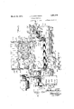
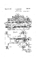
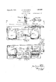
- Fig. 1 is a front elevation of the .whole machine
- Fig. 2 is a plan view of the machine, with parts of the casing broken away or removed and with the pattern table cover removed;
- Fig. 3 is a left end elevation of the machine
- Fig. 4 is a partial transverse section, taken on the line 4-4 of Fig.2, and showing the movable support for the right-hand end of the work shaft;
- Fig. 5 is a longitudinal sectional view of the upper part of the machine on a larger scale than Fig. 1 looking from the front and taken on the line 55 of Fig. 2;
- Fig. 6 is a fragmentary sectional view taken on the line 66 of Fig. 7, showing the hinge of the casing;
- Fig. 7 is a transverse sectional view of the upper portion of the machine, taken on the line 77 of Fig. 2 and line 7 of Fig. 1, but on a larger scale and omitting the pattern table casing;
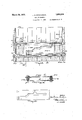
- Fig. 8 is a fragmentary sectional view looking from the right-hand end of the machine and showing the front part of the tool carriage sectioned on the line 8-8 of Fig. 1 and Fig. 2; i
- Fig. 9 is a sectional View looking from the back of the machine and showing on a larger scale the front part of the tool carriage sectioned on the line 99 of Fig. 7;
- Fig. 10 is a plan view, on the scale of Fig. 7, of the tool carriage, with parts broken away and parts above the tool carriage omitted;
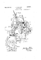
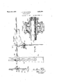
- Fig. 11 is a view looking from the left hand end of the machine, sectioned on the line 1111 of Fig. 2 and showing the feeler and its mounting and associated parts in elevation on a larger scale;
- Fig. 12 is a bottom view of the parts shown in Fig. 11 sectioned on the line 1212 of Fig. 11; v
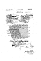
- Fig. 13 is a plan view of the pattern table showing the two parts of the pattern each formed by ashort metal plate;
- Fi 13A is a detail view showing pattern mem ers for forming the work to the shape indicated by the dotted lines in Fig. 1;
- Fig. 14 is a detail sectional view of parts shown in Fig. 13 taken on the line 14-14 of Fig. 13; I
- Fig. 15 is an enlarged detail section on the line 15-15 of Fig. 13;
- Fig. 16 is a broken plan View of the pattern table showing a third type of pattern thereon; and corresponding modifications in the means for holding the pattern.
- Fig. 17 is a view in elevation of the pattern table looking from the left hand end of the machine and showing the pattern table carrying the type of pattern shown in Fig. 16;
- Fig. 18 is an enlarged detail section taken on the line 18-18 of Fig. 16 and showing one of the slides carrying a clamp for the type of pattern shown in Fig. 16;
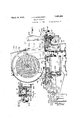
- Fig. 19 is a view, on a larger scale and looking from the left hand end of the machine, of the solenoid box with its hinged cover broken away and showing the parts within the box, partly in section.
- Fig. 20 is a plan view of the parts shown in Fig. 19 sectioned on the line 20-20 of Fig. 19; i
- Fig. 21 is a detail plan view showing part of the linkage between the solenoids and the reversing gear
- Fig. 22 is a detail section on the line 22-22 of Fig. 21;
- Fig. 23 is a plan view on a larger scale showing the parts within the gear box, the cover of the box being removed;
- Fig. 24 is a view taken on line 24-24 of Fig. 23 and line 2424 of Fig. 25 looking .from the left-handend of the machine and showing parts Within the gear box;
- Fig. 25 is a fragmentary sectional view taken on the line 2525 of Fig. 23;
- Fig. 26 is an enlarged plan view of those parts in the gear box which control the feeding movement of the tool;
- Fig. 27 is a vertical section on the line 27-27 of Fig. 26;
- Figs. 28 and 29 are vertical sections on the line 2829 of Fig. 26 showing different positions of the feed control parts;
- Fig. 30 is a plan view of the feed control slide
- Fig. 31 is an enlarged axial section of the bearing at the right hand end of the work shaft
- Fig. 32 is a front elevation of-the mounting for a templet to be used when the machine is controlled manually, this mounting being alsoshown at the top of Fig. 3;
- Fig. 33 is an enlarged section on the line 33 33 of Fig. 32;
- Fig. 34 is a fragmentary edge elevation of a part of the mounting shown in Fig. 32;
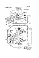
- Fig. 35 is a diagram of the electrical circuits of the machine.
- the dressing machine shown in the drawings is a machine of the lathe type. It has a framework A comprising a hollow, boxlike table or bed A1 supported on legs A2. Standards A3, A4, A5 rising from the table carry bearings for a power-driven mandrel or shaft B on which the work is carried. On
- the table A1 are two longitudinal ways C1 on which the tool carriage C is slidably mounted.
- the tool carriage extends across the table and carries a -cross slide C2 beneath the work shaft B.
- the tool D is carried by a tool thus moves withthe tool and which cooperates with a pattern F carried on an'adj usable pattern table F 1 mounted at the rear of the bed A1 of the machine.
- the top of the bed-A1 between the ways Cl and'between the standards A3 and A4 at one end and the standard A5 at the other end is-cut away, so that the top of the bed is open beneath the work.
- the usual traverse worm G (Figs.
- the traverse worm G is driven through a reversing clutch G2, which is electrically controlled by a flow of current in circuits which include as contact terminals the feeler E and the parts of the pattern F, in such manner that the direction of movement of the carriage is reversed from left to right when the feeler strikes the left-hand part of the pattern and from right to left when the feeler strikes the right-hand part of the pattern.
- the feed worm H is driven through a friction clutch H2 and is held against movement except at the moment of the reversal of the movement of the carriage. At each such reversal, the feed worm is turned an-amount which may be adjusted, so that at each cut the tool is slightly nearer the axis of the work than on the previous cut.
- the reversing clutch G2 (Fig. 23) and friction clutch H2 and cooperating parts are located in a gear box G3 at the left hand end of the bed A1. 7
- the pattern table F1 (Figs. 2, 7 and 13 to 17 is mounted on a bracket A6 extendin g rearwardly from the main bed A1 of the m. L-
- 'llie table is mounted to slide longitudinally of the machine on a cross slide F2 which is mounted to slide transversely of the machine on the bracket A6, the table beingmoved longitudinally of the machine by means of a worm shaft F3 on the cross slide F2 engaging'a nut on the table, and'the cross slide and table being moved transversely of ithe machine by means of a worm shaft F4 on the bracket A6 extending through a hat on the cross. slide.
- the worm shafts E3 and F4 are rovided IIith hand as? shown in Figs. and 17, by turning which the position of the table be adjusted as desired.
- the table is provided at its opposite transverse side edges with upwardly extending flanges F5 and F6,
- a iflat conducting plate F7 which is insulated from the table and is covered by a top plate F8 of insulating material.
- the plates F8 and F7 are formed with a multiplicity of closely spaced sockets F9 for receiving contact plugs as hereinafter explained.
- Extending adj acent the edge flanges F5 and F6 and insulated therefrom are two contact strips or rails F11 and F12 of conducting material.
- the flanges F5 and F6 are formed to serve as guideways for slides F13 and F14 which carry a metal cross bar F15 extending across the table longitudinally of the machine.
- Reduced flattened ends of the cross bar are seated in receiving slots in insulated metal cappieces F17 carried by the slides F13 and F14.
- One of the cap pieces, as that carried by the slide F13, is provided with a spring contact F18 which bears on the contact rail F11, thereby electrically connecting the cross bar F 15 with the rail F11.
- a thumb screw F19 is provided to screw into the cap piece and bear down'against the end of the bar, as shown in Fig. 15.
- the pattern table is provided with only one cross-bar, but when using a pattern having both right and left hand members formed by templets, as shown in Fig.
- a second cross bar F20 is provided carried by slides F21 and F22 which are l'ike the slides- F13 and'F14 except that in this case it is the right hand slide F22 which has its cap piece provided with a spring contact device F 24 hearing against therail F12.
- the cross bar F15 will thus be electrically connected with the rail Flland insulated from the rail F12,v
- the conducting plate F7 is electrically connected with the contact rail F12,
- a hinged cover F25 (Fig. 3) is pr0- vided for the pattern table, which may be swung upward to give access to the table.
- the pattern has a left hand member, or part, F30
- the templet F30 is the pattern proper, its front edge being shaped accordi'ngto the shape to which the work is to be formed, and the plugs F31, forming the right hand pattern member in this case, serve merely to determine the points at which the traversing movement of the carriage is reversed from right to left after the tool has completed a cutting movement to the right.
- the plugs are most desirably arranged in such suitable sockets F9 as to suitably limit the waste, or non-cutting, movement of the tool.
- the righthand member of the pattern consists of a sheet metal templet F31 mounted on the cross bar F20 and insulated from the cross bar F15 by insulating material F15 secured to the lower side of said cross bar, and the left hand member is formed by a sheet metal templet F30 like the templet F30 of Fig. 2 except that the extreme left hand portion of the templet is extended to be supported by insulating material F20 on the cross bar F20 so that it does not make electrical contact with the cross bar F20. Similarly, the extreme right hand end portion of the plate F31 is extended and supported by the bar F15 without being in electrical contact therewith.
- the left hand member F30 of the pattern carried by the bar F15 is thus in electrical contact with the rail F11
- the right hand member F31 of the pattern carried by the bar F20 is in electrical contact with the rail F12.
- the forward edge of the plate F30 determines the shape to which the Work is to be formed, and the plate F31 serves, with a pattern such as shown in Fig.
- the templet F31 desirably has its rear edge shaped to correspond substantially to' the shape of the front edge of the templet F30, and the two telnplets are relatively so set, as shown in Fig. 13, that while the necessary space is' left between the edges of the templets for movement of the feeler, unnecessary waste movement of the/carriage and tool is avoided. It is apparent that when templets are used for both the right hand and left hand members of the pattern, the contact plugs F31 are not required, and the conducting plate F7 and insulating plate F8 providing the sockets F9 .mav be omitted.
- the patterns shown in Figs. 2 and 13 cause the work to be shaped as shown by full lines in Figs. 1 and 5. If the work is to be shaped with an intermediate part of least diameter and parts of greater diameter on each side of such part of least diameter, then the points I of reversal of the carriage at the end of it's traversing movements to the right must be accurately controlled by the pattern for shaping the portion of the work to the right of the partof least diameter, and this is accomplished by providing a templet forming the right hand member of the pattern with a contact edge of the proper shape. For example, for forming the work with its right hand end portion of the shape indicated by dotted lines in Fig. 1, two templets of the shape shown in Fig. 13A would be used.
- Figs. 16,17 and 18 show a pattern made up of a number of thin metal strips F40 placed on edge on the insulating top F8 of the pat tern table beneath a clamping bar F41 which is carried by slides F42 and F43 mounted on the table flanges F5 and F6.
- Insulating material F44 on the under sidexof the bar F41 bears against the top edges of the strips F40 to hold them in place and to insulate them'from the bar.
- the strips are arranged so that their front ends form the pattern outline which is to be formed on the work, and the strips with a strip of insulating material F45 inserted at the deepest point of the outline of the pattern fill the space between the contact rails F11 and F12.
- the strips to the rightof the insulating strip F45 form a right hand pattern member F30 which is in electrical contact with the contact strip F11, and the strips to the left of the insulating strip .form a left hand pattern member F31 which is in contact with the rail F12.
- a pattern formed only by strips F40 as shown in Figs. 16 and 18,
- the sockets may, of course, be omitted from the table top, and the conducting plate F8 electrically connected with one of the contact rails F11 or F12 may also be omitted.
- the feeler E carried by the cross slide G2 at the rear end thereof for cooperating with ,the pattern is made of conductive material.
- It is formed by a short bar or finger of conducting. material mounted on and insulated connected through rails F11 and F12 so that scribed, in the closing of a circuit by which movement of all moving parts of the machine is stopped.
- the feeler might be rigidly mounted on. the cross slide C2 of the tool carriage. Most desirably, however, the feeler is mounted so that it may have a limited movement relative to the cross .slide,
- Figs. 11 and 12 which .show the rear end of the cross slide and a box E1 depending therefrom.
- the feeler E is mounted on and insulated from a shaft E2 which is capable of both turning and sliding in bearings E3 depending from the crossslide.
- the sidewise movements of the feeler E and sliding of the shaft E2 with respect to the slide are utilized to operate emergency switches E4 and E5 forming part of control circuits equivalent in causing reversal of the movement of the tool carriage to the control circuits which are closed when the feeler touches either part of the pattern.
- the movable members E6 and E7 of the emergency switches E4 and are mounted on levers E8 and E9 pivoted at E10 and E11 respectively to the outer ends of tong members E12 and E13 which are independently pivoted on a stud E14 and have their other ends E15 and E16 lying on opposite sides of an arm E17 extending rearwardly from the upper end of the feeler E.
- Pairs of springs E18, E19 urging the lever-s E8 and E9 against stop pins E20 and E21 serve normally to hold the switches E4 and E5 openand to hold the feeler E in its central position.
- E20 and E21 and the studs to. which the springs E18 and E19 are connected all have insulating mountings.
- the feeler is normally held standing in the position shown in Fig. 11 undertension of a spring E23 which extends between the end of an arm E24 secured fast to the shaft E2 and a hook E25, this spring acting normally to hold the arm E24 against a stop bar E26 carried by a bracket depending from the slide C2.
- a spring E23 which extends between the end of an arm E24 secured fast to the shaft E2 and a hook E25, this spring acting normally to hold the arm E24 against a stop bar E26 carried by a bracket depending from the slide C2.
- Excessive pressure pushing the feeler toward the front of the machine will overcome the tension of the spring E23, and the feeler will move backward swinging the arm E17 upward.
- Such upward movement of the arm E17 opens a normally closed emergency switch E22 through engagement with a block E27 of insulating material which hangs from the movable member of the emergency switch;
- the switch E22 is so connected that the opening of this switch serves to stop all movement of moving parts of the machine.
- the feeler In order that the feeler may be conveniently inserted betweenthe two parts of a pattern
- the lower part of the feeler is pivoted to the upper portion thereof at E30 so that it may be turned rearwardly and upwardly into the position shown by dotted lines in Fig. 11.
- the construction is such,
- the electric circuits which are closed by direction when the feeler contacts with one member of the pattern and in the opposite direction when the feeler contacts with the other member of the pattern.
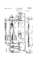
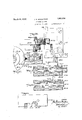
- the core bar K3 is supported by a slide head K4 carried by par-- on a shaft G7 which is driven by a power shaft L through a worm G8 and gear G9, and serves to lock to the shaft'G7 one or the other of two bevel gears G10 and G11, mounted free to turn on the shaft, and both of which mesh with a bevel gear G12 mounted on the left hand end of the traverse worm G.
- the solenoid K2 having been energized to move the core bar K3 to the position shown in Figs. 19 and 20, as the core bar reaches the end of its movement the push member K16 opens the switch K12 and through the con necting rod K13 closes the switch K11; and as the core bar reaches the end of a movement in the opposite direction when attracted by the solenoid K1, the switch K11 is opened by the push member K15 and the switch K12 is closed.
- the feed worm H (Figs. 7, 9 and 10) is con.- nected through spur gears H3, H4 and H5 and a bevel gear H6 to a bevel gear H7 which travels with the tool carriage C but has a splined connection with a longitudinal shaft H8 mounted in bearings on the bed of the machine.
- This shaft H8 (Figs. 23, 24 and 3) is driven from the power shaft L through spur giears H9, H10, H11, H12, the friction clutch 2, shaft H13, an adjustable ratchet reducing mechanism H14 (Fig. 3), shaft H15, and spur gears H16 and H17.
- the driven member of the friction clutch and the shaft H13 to which it is secured are normally held against rotation by the engagement of a stud H20 on the periphery of a disk H21 on the shaft H13 with a slide H22.
- This slide is connected through a bell crank lever H23 and link H24 with an arm H25 on the clutch shifting rock shaft G4, so that it is moved alternately in opposite directions at each reversal of movement of the carriage.
- the slide H22 (Figs. 26-30) contains a longitudinal slot H26 which divides its operative edge into an upper flange H27 and a lower flange H28.
- the feed worm H is turned an amount which depends on the adjustment of the adjustable crank pin H30, and which may be varied by adjusting the crank pin H30 to vary the throw of the connecting rod H31 of the ratchet reducing mechanism H14.
- the upper flange H27 of the slide H22 has two cut-outs H32 and H33, which permit the passage of the stud H20 when the slide is at either end of its travel, and an obstruction H34 between the cut-outs, which is engaged by the stud H20 in case, through a failure of the clutch shifting means, the slide H22 should be moved to release the stud and then remain in such intermediate position (see Fig. 29). This prevents any continuous feeding movement which might otherwise occur under these circumstances with resulting damage to the tool and the work.
- the power shaft L and the work shaft B are most desirably both driven from a single electric motor L1, so that the rotation of the work shaft as well as that of the power shaft L may be stopped by merely cutting off current to this motor.
- the motor L1 carries a sprocket L2 connected by a driving chain L3 to a sprocket L4 on the work shaft.
- Another sprocket L5 on the work shaft is connected by a similar chain L6 to a sprocket L7 on the power shaft L.
Landscapes
- Engineering & Computer Science (AREA)
- Mechanical Engineering (AREA)
- Control Of Cutting Processes (AREA)
Description
' March 29, 1932.
SHAPING MACHINE Filed Oct. 5, 1926 J. S. DONALDSON 14 Sheets-Sheet 1 INVENTOR ATTORNEY March 29, 1932. Y J. 5. DONALDSON 1,851,004 SHAPING MACHINE Filed 00 5, 1926 14 sheets-sheet 2 l l I l /Z 2: nwmroh Ill 1; Afro/my March 29, 1932. DQNALDSON 1,851,004
SHAPING MACHINE Filed Oct. 5, 1926 14 Sheets-Sheet 5 1W3 A'rramvsy 29, 1332. J. s. DONALDSON SHAPING MACHINE Filed Oct. 5, 1926 14 Sheets-Sheet 4 I I I l l l l I I I l l T I l I l I.
INVENTOR Mm M M A; ATTORNEY J. S. DONALDSOIN I SHAPING MACHINE March 29, 1932.
Filed Oct. 5, 1926 14 Sheets-Sheet 5 1/ 1M MWDN .NUBN
e M\\ WWW M m M w n w r -L EF & H .L
""Ni'rh 2 9, 1932..
l J. 5. DONALDSON 1,851,004
SHAPING MACHINE Filed 00L s, 1926 14 Sheets-Sheet e v E Ww INVENTOR M w M L; ATII'ORNEY Marc 29, 1932. J. 5. DONALDSON SHAPING MACHINE Filed Oct. 5, 1926 14 Sheets-Sheet 7 M M M w IVEY 1 [Tron March 1932' JUS. DONALDSYON 1,851,004
SHAPING MACHINE Filed 001;. 5, 1926 14 Sheets-Sheet 8 mmmn March 29, 1932. J 5 DONALDSQN 1,851,004
ISHAPINQYMACHINE 0 Fi ed Oct. 5, 1926 124 Sheets-Sheet 9 09000 000090 ooooooooooooo oooooopeoooo eooooooo'ooo ooooooooooo 900000-0000 0 00000000000 oooooQoooo 00000000 60 0900000000 0 000600. 0 oooooooe INVENTOR A; TTORNEY March 29, 1932. 5, DONALDSON 1,851,004
' SHAPING MACHINE Filed Oct. 5, 1926 14 Sheets-Sheet 1o INVENTOR Z; AITTOHNEY March 29, 1932. J. s. DONALDSQ'N 1 51 004 7 SHAPING MACHINE Filed 001;. 5, 1926 14 sheets sheey 11 24 3 T:fi.2-
* nvmvrog 3%- a i d M A TTOR/VEY March 29, 1932' J. s. DONALDSON v v 1,851,004
SHAPING MACHINE Filed Oct. 5. 1926 14 Sh'eets-Sheet 15 GIN . a INVENTOR MM um-10w ATTORNEY I w g/bf March 29, 1932.
J. S. DONALDSON SHAPING MACHINE 14 Sheets-Sheet l4 4 Filed 0st 5, 1926 INVENTOI? MUM A; AfTOHA/EY Patented Mar. 29, 1932 r .Tomr smunm DONALDSON, or m YORK, 11. Y.
srmrme mom I Application filed October 5, 1926. Serial No. 139,587.
This invention relates to automatic shaping machines, and aims to provide an improved machine for cutting or otherwise forming the work automatically in accordance with a pattern. a The invention relates particularly to the type of machine in which a cutting or other tool is mounted on the cross slide of a carriage, so that the tool may be moved in two directions at right angles to each other, and in which the cross slide-carries also a feeler which cooperates with a pattern to guide the movements of the tool. v the movement of the tool along the surface of the work is known as a traversing movement, while movement of the tool directly toward or away from the work is termed a feeding movement. When the machine is of the lathe type, the traversing movement is obtained by moving the tool carriage parallel to the axis of the work, and the feeding movement is obtained by moving the cross slide of the tool carriage toward or away from the axis of the work; c In all previous automatic machines of this character, so far as I am aware, the feeler and pattern have been used to control automatically the feeding movement of the tool during the traverse of the tool, in such manner as to make the tool move during each cut in a path which has substantially the same shape as the outline of the pattern. This arrangement possesses serious disadvantages, in that it involves much waste of time when the original form of the work is materially different from its final shape, as in this case' all the 'initials cutsStrike the work only in line with those parts of it which are towbe out most. deeply in its final form. Afurther disadvantage of such machines is that they cannot sha the work in accordance-with patterns w o'se outline contains right angle corners. The present'invention does away with these disadvantages by utilizing the pattern and feeler to control the length of each traverse of contact with the pattern, the directl traversing movement is reversed,
reversal of the traversing movement, the tool of the In such machines,
the tool. Whenever the feeler comes in is fed in slightly toward the work; As a result, the work is given a shape corresponding to that of the pattern by means of a series of straight parallel cuts. But little time need be wasted, since in most cases the tool may 65 be controlled so that it will be cutting throughout substantially all of each of its traversing movements. Furthermore, the presence of right angle corners on the pattern in no way interferes with the operation, and such corners are correctly reproduced on the work. 7 v
A further feature of the present invention consists inobtainingaccurate control of the tool by the pattern by doin away with the v lag between contact of the fee er with the pattern and control of the tool which has existed in some previous machines. Such lag has resulted from the fact that it has beencustomary to rely upon a movement of the feeler in,its holder, caused by pressing it against the pattern, to control the movement of the tool. .In accordance with the present invention, the control of the-tool follows substantially instantaneously when thefeeler 7 touches the pattern. This result is obtained by making both the feeler and the pattern-- of electrically conductive material, and connecting them as contact terminals in control circuits, and utilizing a flow of electric current in such circuits to cause the actuation of the mechanism which controls the movements of the tool. A mere touching of the feeler against the pattern is,. therefore, suflicient to cause the operation of the controlling mechanism, and the lag heretofore caused b pressing the feeler against thepattern s cientl ,to alter its position in its holder is eliminate While the features of the invention -to -which reference has been made may. advantageously be applied tovarious automatic cutting or grinding machines, such, for example, aslat-hes or planing machines for shaping. various -materials, the invention possesses peculiar advantages when incorporated in a machine for gnnding wheels and is believed to produce the first snccemful automatic machine for this purd at each pose.
The invention involves many other lmpor- 10v (ill tant novel features, all of which may best be understood from a detailed description of a practical machine for dressing grinding wheels embodying the invention and illustrated in the accompanying drawings, in which Fig. 1 is a front elevation of the .whole machine;
Fig. 2 is a plan view of the machine, with parts of the casing broken away or removed and with the pattern table cover removed;
Fig. 3 is a left end elevation of the machine;
Fig. 4 is a partial transverse section, taken on the line 4-4 of Fig.2, and showing the movable support for the right-hand end of the work shaft;
Fig. 5 is a longitudinal sectional view of the upper part of the machine on a larger scale than Fig. 1 looking from the front and taken on the line 55 of Fig. 2;
Fig. 6 is a fragmentary sectional view taken on the line 66 of Fig. 7, showing the hinge of the casing;
Fig. 7 is a transverse sectional view of the upper portion of the machine, taken on the line 77 of Fig. 2 and line 7 of Fig. 1, but on a larger scale and omitting the pattern table casing;
Fig. 8 is a fragmentary sectional view looking from the right-hand end of the machine and showing the front part of the tool carriage sectioned on the line 8-8 of Fig. 1 and Fig. 2; i
Fig. 9 is a sectional View looking from the back of the machine and showing on a larger scale the front part of the tool carriage sectioned on the line 99 of Fig. 7;
Fig. 10 is a plan view, on the scale of Fig. 7, of the tool carriage, with parts broken away and parts above the tool carriage omitted;
Fig. 11 is a view looking from the left hand end of the machine, sectioned on the line 1111 of Fig. 2 and showing the feeler and its mounting and associated parts in elevation on a larger scale;
Fig. 12 is a bottom view of the parts shown in Fig. 11 sectioned on the line 1212 of Fig. 11; v
Fig. 13 is a plan view of the pattern table showing the two parts of the pattern each formed by ashort metal plate;
Fi 13A is a detail view showing pattern mem ers for forming the work to the shape indicated by the dotted lines in Fig. 1;
Fig. 14 is a detail sectional view of parts shown in Fig. 13 taken on the line 14-14 of Fig. 13; I
Fig. 15 is an enlarged detail section on the line 15-15 of Fig. 13;
Fig. 16 is a broken plan View of the pattern table showing a third type of pattern thereon; and corresponding modifications in the means for holding the pattern.
Fig. 17 is a view in elevation of the pattern table looking from the left hand end of the machine and showing the pattern table carrying the type of pattern shown in Fig. 16;
Fig. 18 is an enlarged detail section taken on the line 18-18 of Fig. 16 and showing one of the slides carrying a clamp for the type of pattern shown in Fig. 16;
Fig. 19 is a view, on a larger scale and looking from the left hand end of the machine, of the solenoid box with its hinged cover broken away and showing the parts within the box, partly in section.
Fig. 20 is a plan view of the parts shown in Fig. 19 sectioned on the line 20-20 of Fig. 19; i
Fig. 21 is a detail plan view showing part of the linkage between the solenoids and the reversing gear;
Fig. 22 is a detail section on the line 22-22 of Fig. 21;
Fig. 23 is a plan view on a larger scale showing the parts within the gear box, the cover of the box being removed;
Fig. 24 is a view taken on line 24-24 of Fig. 23 and line 2424 of Fig. 25 looking .from the left-handend of the machine and showing parts Within the gear box;
Fig. 25 is a fragmentary sectional view taken on the line 2525 of Fig. 23;
Fig. 26 is an enlarged plan view of those parts in the gear box which control the feeding movement of the tool;
Fig. 27 is a vertical section on the line 27-27 of Fig. 26;
Figs. 28 and 29 are vertical sections on the line 2829 of Fig. 26 showing different positions of the feed control parts;
Fig. 30 is a plan view of the feed control slide;
Fig. 31 is an enlarged axial section of the bearing at the right hand end of the work shaft;
Fig. 32 is a front elevation of-the mounting for a templet to be used when the machine is controlled manually, this mounting being alsoshown at the top of Fig. 3;
Fig. 33 is an enlarged section on the line 33 33 of Fig. 32;
Fig. 34 is a fragmentary edge elevation of a part of the mounting shown in Fig. 32; and
Fig. 35 is a diagram of the electrical circuits of the machine.
The dressing machine shown in the drawings is a machine of the lathe type. It has a framework A comprising a hollow, boxlike table or bed A1 supported on legs A2. Standards A3, A4, A5 rising from the table carry bearings for a power-driven mandrel or shaft B on which the work is carried. On
the table A1 are two longitudinal ways C1 on which the tool carriage C is slidably mounted. The tool carriage extends across the table and carries a -cross slide C2 beneath the work shaft B. The tool D is carried by a tool thus moves withthe tool and which cooperates with a pattern F carried on an'adj usable pattern table F 1 mounted at the rear of the bed A1 of the machine. The top of the bed-A1 between the ways Cl and'between the standards A3 and A4 at one end and the standard A5 at the other end is-cut away, so that the top of the bed is open beneath the work. The usual traverse worm G (Figs. 9, extending lengthwise of the ma,- chine and cooperating with a nut G1 on the tool carriage is provided to cause the traversing movements of the tool. The usual feed worm H carried by the carriage and cooperating with a nut H1 on the cross slide is provided to causefeeding movements of the tool. The traverse worm G is driven through a reversing clutch G2, which is electrically controlled by a flow of current in circuits which include as contact terminals the feeler E and the parts of the pattern F, in such manner that the direction of movement of the carriage is reversed from left to right when the feeler strikes the left-hand part of the pattern and from right to left when the feeler strikes the right-hand part of the pattern. The feed worm H is driven through a friction clutch H2 and is held against movement except at the moment of the reversal of the movement of the carriage. At each such reversal, the feed worm is turned an-amount which may be adjusted, so that at each cut the tool is slightly nearer the axis of the work than on the previous cut. The reversing clutch G2 (Fig. 23) and friction clutch H2 and cooperating parts are located in a gear box G3 at the left hand end of the bed A1. 7
The pattern table F1 (Figs. 2, 7 and 13 to 17 is mounted on a bracket A6 extendin g rearwardly from the main bed A1 of the m. L-
chine. 'llie table is mounted to slide longitudinally of the machine on a cross slide F2 which is mounted to slide transversely of the machine on the bracket A6, the table beingmoved longitudinally of the machine by means of a worm shaft F3 on the cross slide F2 engaging'a nut on the table, and'the cross slide and table being moved transversely of ithe machine by means of a worm shaft F4 on the bracket A6 extending through a hat on the cross. slide. The worm shafts E3 and F4 are rovided IIith hand as? shown in Figs. and 17, by turning which the position of the table be adjusted as desired. The table is provided at its opposite transverse side edges with upwardly extending flanges F5 and F6,
and isprovided between the flanges with a iflat conducting plate F7 which is insulated from the table and is covered by a top plate F8 of insulating material. The plates F8 and F7 are formed with a multiplicity of closely spaced sockets F9 for receiving contact plugs as hereinafter explained. Extending adj acent the edge flanges F5 and F6 and insulated therefrom are two contact strips or rails F11 and F12 of conducting material. The flanges F5 and F6 are formed to serve as guideways for slides F13 and F14 which carry a metal cross bar F15 extending across the table longitudinally of the machine. Reduced flattened ends of the cross bar are seated in receiving slots in insulated metal cappieces F17 carried by the slides F13 and F14. One of the cap pieces, as that carried by the slide F13, is provided with a spring contact F18 which bears on the contact rail F11, thereby electrically connecting the cross bar F 15 with the rail F11. To insure good contact of the end of the bar F15 in its seat in this cap piece F17, a thumb screw F19 is provided to screw into the cap piece and bear down'against the end of the bar, as shown in Fig. 15. As shown in Fig. 2, the pattern table is provided with only one cross-bar, but when using a pattern having both right and left hand members formed by templets, as shown in Fig. 13, a second cross bar F20 is provided carried by slides F21 and F22 which are l'ike the slides- F13 and'F14 except that in this case it is the right hand slide F22 which has its cap piece provided with a spring contact device F 24 hearing against therail F12. The cross bar F15 will thus be electrically connected with the rail Flland insulated from the rail F12,v
and the cross bar F20 will be electrically connected 'with the rail F12 and insulated from the rail F11. The conducting plate F7 is electrically connected with the contact rail F12,
andthe two rails F11 and F12 are connected one in each of two control circuits, of each of which one of the pattern members hereinafter described formsa terminal and which have a common terminal in the feeler E, so that when the feeler makes contact with either pattern member, one of these control circuits closed. A hinged cover F25 (Fig. 3) is pr0- vided for the pattern table, which may be swung upward to give access to the table.
The pattern, or means which serves to de-'- termine the points of reversal of the successive traversing movements of the tool earriage to form the work to the desired shape,
consists of right and left hand parts each -l'2o made wholly or partly of conducting material and electrically connected, when mounted on the pattern table, to the contact rails F11 and.
F12 respectively. -As, shown in Fig. 2, the pattern has a left hand member, or part, F30
consisting of a sheet metal templet secured to and carried by the cross bar F15, so that it is electrically connected to the rail F 11, and a right hand part consisting 'of a number of separate plugs F31 inserted insome of the sockets F9 so that they are electrically eonnected through the plate F7 with the rail F12. The templet F30 is the pattern proper, its front edge being shaped accordi'ngto the shape to which the work is to be formed, and the plugs F31, forming the right hand pattern member in this case, serve merely to determine the points at which the traversing movement of the carriage is reversed from right to left after the tool has completed a cutting movement to the right. The plugs are most desirably arranged in such suitable sockets F9 as to suitably limit the waste, or non-cutting, movement of the tool.
As shown in Figs. 13 and 14, the righthand member of the pattern consists of a sheet metal templet F31 mounted on the cross bar F20 and insulated from the cross bar F15 by insulating material F15 secured to the lower side of said cross bar, and the left hand member is formed by a sheet metal templet F30 like the templet F30 of Fig. 2 except that the extreme left hand portion of the templet is extended to be supported by insulating material F20 on the cross bar F20 so that it does not make electrical contact with the cross bar F20. Similarly, the extreme right hand end portion of the plate F31 is extended and supported by the bar F15 without being in electrical contact therewith. The left hand member F30 of the pattern carried by the bar F15 is thus in electrical contact with the rail F11, and the right hand member F31 of the pattern carried by the bar F20 is in electrical contact with the rail F12. As in Fig. 2, the forward edge of the plate F30 determines the shape to which the Work is to be formed, and the plate F31 serves, with a pattern such as shown in Fig. 13 merely to limit the amount of continued movement of the carriage and tool'to the right after each cutting stroke to the right has been completed, but in order to avoid loss of time through unnecessary waste movement of the carriage and tool after the tool leaves the surface of the work on each movement to the right with a pattern such as shown, the templet F31 desirably has its rear edge shaped to correspond substantially to' the shape of the front edge of the templet F30, and the two telnplets are relatively so set, as shown in Fig. 13, that while the necessary space is' left between the edges of the templets for movement of the feeler, unnecessary waste movement of the/carriage and tool is avoided. It is apparent that when templets are used for both the right hand and left hand members of the pattern, the contact plugs F31 are not required, and the conducting plate F7 and insulating plate F8 providing the sockets F9 .mav be omitted.
The patterns shown in Figs. 2 and 13 cause the work to be shaped as shown by full lines in Figs. 1 and 5. If the work is to be shaped with an intermediate part of least diameter and parts of greater diameter on each side of such part of least diameter, then the points I of reversal of the carriage at the end of it's traversing movements to the right must be accurately controlled by the pattern for shaping the portion of the work to the right of the partof least diameter, and this is accomplished by providing a templet forming the right hand member of the pattern with a contact edge of the proper shape. For example, for forming the work with its right hand end portion of the shape indicated by dotted lines in Fig. 1, two templets of the shape shown in Fig. 13A would be used.
Figs. 16,17 and 18 show a pattern made up of a number of thin metal strips F40 placed on edge on the insulating top F8 of the pat tern table beneath a clamping bar F41 which is carried by slides F42 and F43 mounted on the table flanges F5 and F6. Insulating material F44 on the under sidexof the bar F41 bears against the top edges of the strips F40 to hold them in place and to insulate them'from the bar. The strips are arranged so that their front ends form the pattern outline which is to be formed on the work, and the strips with a strip of insulating material F45 inserted at the deepest point of the outline of the pattern fill the space between the contact rails F11 and F12. The strips to the rightof the insulating strip F45 form a right hand pattern member F30 which is in electrical contact with the contact strip F11, and the strips to the left of the insulating strip .form a left hand pattern member F31 which is in contact with the rail F12. Obviously, one or mpre' of the contact plugs F31 might be inserted in the sockets of the insulated table top to form the right hand pattern member to cooperate with the pattern portion F30. If a pattern formed only by strips F40, as shown in Figs. 16 and 18,
is to be used, the sockets may, of course, be omitted from the table top, and the conducting plate F8 electrically connected with one of the contact rails F11 or F12 may also be omitted.
It should be noted that in all of the patterns 1 shown the right and left hand members of the pattern are electrically separated but closely spaced at the deepest point of the outline of the pattern.
The feeler E carried by the cross slide G2 at the rear end thereof for cooperating with ,the pattern is made of conductive material.
It is formed by a short bar or finger of conducting. material mounted on and insulated connected through rails F11 and F12 so that scribed, in the closing of a circuit by which movement of all moving parts of the machine is stopped.
, So far as the normal operation of the machine is concerned, the feeler might be rigidly mounted on. the cross slide C2 of the tool carriage. Most desirably, however, the feeler is mounted so that it may have a limited movement relative to the cross .slide,
and such relative movement of the feeler with respect to the cross slide caused by pressing the feeler against the pattern is utilized' to operate a safety switch, the
operation of which results in the reversal of the traverse movement of the tool carriage. In this way damage to the work or to the tool or other parts of the machine which might occur through failure of the reversing mechanism to operate when the feeler touches the pattern because of the presence of dirt or corrosion or for any other reason is avoided. By the use of such safety switches, preferably controlling circuits of relatively high voltage so that the closing of the circuit would not be affected by the presence of slight corrosion or dirt on the contact surfaces, I am enabled safely to use a comparatively low voltage on the regular control circuits which include the feeler and the pattern, and thus avoid injurious arcing between the feeler and the pattern which would occur with the use of 'high voltage current. i
The mounting of the feeler which I have found most desirable is illustrated in Figs. 11 and 12 which .show the rear end of the cross slide and a box E1 depending therefrom. The feeler E is mounted on and insulated from a shaft E2 which is capable of both turning and sliding in bearings E3 depending from the crossslide. The sidewise movements of the feeler E and sliding of the shaft E2 with respect to the slide are utilized to operate emergency switches E4 and E5 forming part of control circuits equivalent in causing reversal of the movement of the tool carriage to the control circuits which are closed when the feeler touches either part of the pattern. The movable members E6 and E7 of the emergency switches E4 and are mounted on levers E8 and E9 pivoted at E10 and E11 respectively to the outer ends of tong members E12 and E13 which are independently pivoted on a stud E14 and have their other ends E15 and E16 lying on opposite sides of an arm E17 extending rearwardly from the upper end of the feeler E. Pairs of springs E18, E19 urging the lever-s E8 and E9 against stop pins E20 and E21 serve normally to hold the switches E4 and E5 openand to hold the feeler E in its central position. E20 and E21 and the studs to. which the springs E18 and E19 are connected all have insulating mountings. v
The feeler is normally held standing in the position shown in Fig. 11 undertension of a spring E23 which extends between the end of an arm E24 secured fast to the shaft E2 and a hook E25, this spring acting normally to hold the arm E24 against a stop bar E26 carried by a bracket depending from the slide C2. Excessive pressure pushing the feeler toward the front of the machine will overcome the tension of the spring E23, and the feeler will move backward swinging the arm E17 upward. Such upward movement of the arm E17 opens a normally closed emergency switch E22 through engagement with a block E27 of insulating material which hangs from the movable member of the emergency switch; The switch E22 is so connected that the opening of this switch serves to stop all movement of moving parts of the machine. Any further movement of the feeler I E, therefore, such as would be caused by continued operation of the machine after the feeler has reached the deepest part of the outline of the pattern, or by any continued feeding movement of the slide when the feeler is in contact with a forwardly facing edge of the pattern, will cause an emergency stop of the machine.
In order that the feeler may be conveniently inserted betweenthe two parts of a pattern The stud E11, the stoppins with which it is to cooperate, such as the pattern shown in Fig. 13 for example, and that it may, ifdcsired, be adjusted to a position in which it will not come into engagement with a pattern on the pattern table, the feeler is made so that its lower end portion or contacting part may be raised so as to pass over the pattern. For this purpose in the construction shown, the lower part of the feeler is pivoted to the upper portion thereof at E30 so that it may be turned rearwardly and upwardly into the position shown by dotted lines in Fig. 11. The construction is such,
however, that the feeler cannot be turned for wardly with respect to its upper part from the operative position shown by full lines in Fig. 11.
The electric circuits which are closed by direction when the feeler contacts with one member of the pattern and in the opposite direction when the feeler contacts with the other member of the pattern. The core bar K3 is supported by a slide head K4 carried by par-- on a shaft G7 which is driven by a power shaft L through a worm G8 and gear G9, and serves to lock to the shaft'G7 one or the other of two bevel gears G10 and G11, mounted free to turn on the shaft, and both of which mesh with a bevel gear G12 mounted on the left hand end of the traverse worm G. It is apparent that when the clutch member G6 is shifted by the rocking of the shaft G4 by either solenoid, it reverses the direction of rotation of the traverse worm and consequently the direction of the traverse of the tool. An adjustable pivotal connection between the connecting rod K7 and arm K8 provides for varying the effective length of the arm K8 and thereby the throw of the shifting fork G5. In order that the clutch member G6 shall be moved and held against the coacting clutch members under yielding pressure, the connecting rod K7 is formed of two parts connected by means permitting a relative endwise movement between the parts and restrained from such movement,
' bers K15 and K16 mounted on a bracket K17.
The solenoid K2 having been energized to move the core bar K3 to the position shown in Figs. 19 and 20, as the core bar reaches the end of its movement the push member K16 opens the switch K12 and through the con necting rod K13 closes the switch K11; and as the core bar reaches the end of a movement in the opposite direction when attracted by the solenoid K1, the switch K11 is opened by the push member K15 and the switch K12 is closed.
The feed worm H (Figs. 7, 9 and 10) is con.- nected through spur gears H3, H4 and H5 and a bevel gear H6 to a bevel gear H7 which travels with the tool carriage C but has a splined connection with a longitudinal shaft H8 mounted in bearings on the bed of the machine. This shaft H8 (Figs. 23, 24 and 3) is driven from the power shaft L through spur giears H9, H10, H11, H12, the friction clutch 2, shaft H13, an adjustable ratchet reducing mechanism H14 (Fig. 3), shaft H15, and spur gears H16 and H17. The driven member of the friction clutch and the shaft H13 to which it is secured are normally held against rotation by the engagement of a stud H20 on the periphery of a disk H21 on the shaft H13 with a slide H22. This slide is connected through a bell crank lever H23 and link H24 with an arm H25 on the clutch shifting rock shaft G4, so that it is moved alternately in opposite directions at each reversal of movement of the carriage. The slide H22 (Figs. 26-30) contains a longitudinal slot H26 which divides its operative edge into an upper flange H27 and a lower flange H28. When the clutch member G6 is positioned to drive the traverse Worm in either direction, the slide H22 is at one end of its travel and the stud H20 rests on the lower flange H28 at one side of a central cut-out H29 therein, as shown in Fig. 28. When the slide is moved to the other end of its travel by the shifting of the clutch member G6, the stud H20 passes through the cut-out H29, permitting the disk H21 to make one revolution, and thenstrikes the lower flange H28 at the other side of the cut-out H29. At each such revolution of the disk H21 and shaft H13 the feed worm H is turned an amount which depends on the adjustment of the adjustable crank pin H30, and which may be varied by adjusting the crank pin H30 to vary the throw of the connecting rod H31 of the ratchet reducing mechanism H14. The upper flange H27 of the slide H22 has two cut-outs H32 and H33, which permit the passage of the stud H20 when the slide is at either end of its travel, and an obstruction H34 between the cut-outs, which is engaged by the stud H20 in case, through a failure of the clutch shifting means, the slide H22 should be moved to release the stud and then remain in such intermediate position (see Fig. 29). This prevents any continuous feeding movement which might otherwise occur under these circumstances with resulting damage to the tool and the work.
The power shaft L and the work shaft B are most desirably both driven from a single electric motor L1, so that the rotation of the work shaft as well as that of the power shaft L may be stopped by merely cutting off current to this motor. The motor L1 carries a sprocket L2 connected by a driving chain L3 to a sprocket L4 on the work shaft. Another sprocket L5 on the work shaft is connected by a similar chain L6 to a sprocket L7 on the power shaft L.
Different arrangements of electrical circuits may, of course, be provided in order to control the operation of the solenoids K1, K2 by means of a flow of current between the feeler E and the two parts of the pattern F, a W6 as by means of the two emergency
Priority Applications (1)
| Application Number | Priority Date | Filing Date | Title |
|---|---|---|---|
| US139587A US1851004A (en) | 1926-10-05 | 1926-10-05 | Shaping machine |
Applications Claiming Priority (1)
| Application Number | Priority Date | Filing Date | Title |
|---|---|---|---|
| US139587A US1851004A (en) | 1926-10-05 | 1926-10-05 | Shaping machine |
Publications (1)
| Publication Number | Publication Date |
|---|---|
| US1851004A true US1851004A (en) | 1932-03-29 |
Family
ID=22487389
Family Applications (1)
| Application Number | Title | Priority Date | Filing Date |
|---|---|---|---|
| US139587A Expired - Lifetime US1851004A (en) | 1926-10-05 | 1926-10-05 | Shaping machine |
Country Status (1)
| Country | Link |
|---|---|
| US (1) | US1851004A (en) |
Cited By (7)
| Publication number | Priority date | Publication date | Assignee | Title |
|---|---|---|---|---|
| US2469255A (en) * | 1944-11-18 | 1949-05-03 | Bailey Meter Co | Pattern controlled grinding wheel dressing mechanism |
| US2469079A (en) * | 1946-02-07 | 1949-05-03 | Rosenbloom Harry | Machine tool support |
| US2502792A (en) * | 1945-12-05 | 1950-04-04 | Leblond Mach Tool Co R K | Machine tool coolant guard |
| US2777201A (en) * | 1952-06-26 | 1957-01-15 | Kearney & Trecker Corp | Pattern support and adjustable template |
| US2947928A (en) * | 1952-10-07 | 1960-08-02 | Leblond Mach Tool Co R K | Automatic machinist |
| US2996849A (en) * | 1960-02-03 | 1961-08-22 | Musser C Walton | Venturi machining apparatus |
| US3204499A (en) * | 1963-08-09 | 1965-09-07 | Norbert O Schoenrock | Safety shield for wood and metal lathes |
-
1926
- 1926-10-05 US US139587A patent/US1851004A/en not_active Expired - Lifetime
Cited By (7)
| Publication number | Priority date | Publication date | Assignee | Title |
|---|---|---|---|---|
| US2469255A (en) * | 1944-11-18 | 1949-05-03 | Bailey Meter Co | Pattern controlled grinding wheel dressing mechanism |
| US2502792A (en) * | 1945-12-05 | 1950-04-04 | Leblond Mach Tool Co R K | Machine tool coolant guard |
| US2469079A (en) * | 1946-02-07 | 1949-05-03 | Rosenbloom Harry | Machine tool support |
| US2777201A (en) * | 1952-06-26 | 1957-01-15 | Kearney & Trecker Corp | Pattern support and adjustable template |
| US2947928A (en) * | 1952-10-07 | 1960-08-02 | Leblond Mach Tool Co R K | Automatic machinist |
| US2996849A (en) * | 1960-02-03 | 1961-08-22 | Musser C Walton | Venturi machining apparatus |
| US3204499A (en) * | 1963-08-09 | 1965-09-07 | Norbert O Schoenrock | Safety shield for wood and metal lathes |
Similar Documents
| Publication | Publication Date | Title |
|---|---|---|
| US2116593A (en) | Cutting or milling machine | |
| US1851004A (en) | Shaping machine | |
| US2041461A (en) | Welding machine | |
| US3245294A (en) | Means for and method of cutting thermoplastic materials | |
| US1959667A (en) | Control device | |
| US1909138A (en) | Contactor | |
| US1954061A (en) | Device for grooving safety glass | |
| GB559658A (en) | Improvement relating to electric flash welding | |
| US2360375A (en) | Arrangement for electrically controlling operation of machine tools | |
| US1985049A (en) | Tool lifting device | |
| US1451894A (en) | Electric riveting machine and process | |
| US1971297A (en) | Shaping machine | |
| US2435280A (en) | Circuits for tracer controlled machine tools | |
| US2973197A (en) | Article gripping chuck | |
| US2747151A (en) | Control system for machine tools | |
| US1637715A (en) | Manufacture of plastic materials and to apparatus therefor | |
| US1708769A (en) | Welding machine | |
| US2810327A (en) | Electric feeler control system | |
| US2887932A (en) | Control device | |
| US1970919A (en) | Machine for cutting sheets of glass and the like | |
| US2212407A (en) | Tracer controlled milling machine | |
| US1755046A (en) | Electrically-operated pressing machine | |
| US1679917A (en) | Assionob to the akebican laundby | |
| US2293481A (en) | Welding apparatus | |
| US2040892A (en) | Automatic controlling switch mechanism |