US1851003A - Vulcanizing mold - Google Patents
Vulcanizing mold Download PDFInfo
- Publication number
- US1851003A US1851003A US160174A US16017427A US1851003A US 1851003 A US1851003 A US 1851003A US 160174 A US160174 A US 160174A US 16017427 A US16017427 A US 16017427A US 1851003 A US1851003 A US 1851003A
- Authority
- US
- United States
- Prior art keywords
- mold
- tire
- section
- sections
- pair
- Prior art date
- Legal status (The legal status is an assumption and is not a legal conclusion. Google has not performed a legal analysis and makes no representation as to the accuracy of the status listed.)
- Expired - Lifetime
Links
- 230000008093 supporting effect Effects 0.000 description 14
- 239000011324 bead Substances 0.000 description 10
- 210000005069 ears Anatomy 0.000 description 4
- 238000010438 heat treatment Methods 0.000 description 3
- 238000000926 separation method Methods 0.000 description 3
- 238000004073 vulcanization Methods 0.000 description 3
- 210000003414 extremity Anatomy 0.000 description 2
- 239000012530 fluid Substances 0.000 description 2
- 230000002093 peripheral effect Effects 0.000 description 2
- 230000000630 rising effect Effects 0.000 description 2
- 235000007119 Ananas comosus Nutrition 0.000 description 1
- 244000099147 Ananas comosus Species 0.000 description 1
- 241000283986 Lepus Species 0.000 description 1
- 241000906091 Lethrinus miniatus Species 0.000 description 1
- 241000063973 Mattia Species 0.000 description 1
- 238000013459 approach Methods 0.000 description 1
- 230000003190 augmentative effect Effects 0.000 description 1
- 230000006835 compression Effects 0.000 description 1
- 238000007906 compression Methods 0.000 description 1
- 230000005494 condensation Effects 0.000 description 1
- 238000009833 condensation Methods 0.000 description 1
- 238000010276 construction Methods 0.000 description 1
- 238000006073 displacement reaction Methods 0.000 description 1
- 230000000694 effects Effects 0.000 description 1
- 230000005484 gravity Effects 0.000 description 1
- 230000001976 improved effect Effects 0.000 description 1
- 238000003780 insertion Methods 0.000 description 1
- 230000037431 insertion Effects 0.000 description 1
- 238000004519 manufacturing process Methods 0.000 description 1
- 230000008092 positive effect Effects 0.000 description 1
- 238000009877 rendering Methods 0.000 description 1
- 230000000284 resting effect Effects 0.000 description 1
- 239000007787 solid Substances 0.000 description 1
- 210000001364 upper extremity Anatomy 0.000 description 1
Images


Classifications
-
- B—PERFORMING OPERATIONS; TRANSPORTING
- B29—WORKING OF PLASTICS; WORKING OF SUBSTANCES IN A PLASTIC STATE IN GENERAL
- B29D—PRODUCING PARTICULAR ARTICLES FROM PLASTICS OR FROM SUBSTANCES IN A PLASTIC STATE
- B29D30/00—Producing pneumatic or solid tyres or parts thereof
- B29D30/06—Pneumatic tyres or parts thereof (e.g. produced by casting, moulding, compression moulding, injection moulding, centrifugal casting)
- B29D30/0601—Vulcanising tyres; Vulcanising presses for tyres
- B29D30/0603—Loading or unloading the presses
Definitions
- Figs. 11 to 14, inelusive, are detail views of the tire-supporting and stripping mechanism in four diiferent positions during the opening movement of the mold.
- the invention has been shown in the drawings as applied to a vulcanizing mold for use in the manufacture of automobile tires, but the various features are not restricted to this specific embodiment.
- the mold includes a pair of opposed mold sections and 11,
- V which are jacketed in the usual manner to provide steam heating chambers 12 and 13, and said sections being respectively mounted on central supporting members 14 and 15 in the form of circular plates.
- the member 14 is held in xed position by a pair of posts 16 which extend upwardlyT from a base 17, while the member is carried by a pair of swinging arms 18 which are pivoted to the base at 19 below the mold.
- An angular olfset 20 at the lower portion of each arm 18 is so proportioned as to place thecenter of gravity of the swinging mold section 11 close to the pivotal center 19, rendering said arms 18 and their associated parts capable of easy movement in opening and closing the mold.
- the mold sections 10 and 11 are preferably detachable from the supporting members 14 and 15, whereby molds of dilie'rent sizes or different tread designs may be interchanged in a single machine frame, each mold section being provided with an inwardly eX- tending flange 21 of standardized proportions to lit upon annular seats 22 and 23 adjacent the peripheries of the supporting plates 14 and 15, and being fastened thereto by studs or bolts 24.
- the mold sections are capable of relative engagement or separation, as desired, and are capable of being locked together by means which will hereinafter be fully described.
- the inner faces of theopposed mold sections 10 and 11V are respectively provided with the usual mold cavities 25 and 26 having lateral or cylindrical walls 27 which form seats for the bead portions of an unmounted tire 28 during the vulcanizing operation.
- novel means are provided for supporting a tire out of the mold cavities when the mold is open, said means functioning to strip the tire from the mold as it is opened.
- the tire-supporting and stripping mechanism includes a pair of blocks 30 and 31, the block 3() being adapted to seat within arecess 32 in the mold section 10, while the block 31 is adapted to seat within a similar recess 33 in the mold section 11.
- T he recesses 32 and 33 intersect the mold cavities 25 and 26 by virtue ot 'the fact that the walls 27 are grooved as at 34 (Figs.
- the blocks 30 and 31 are provided with extensions 35 and 36, respectively.
- the upper surfaces of the extensions 35 and 36 are formed with cylindrical seat portions 37 which, when the mold is closed, constitute extensions of the annular walls 27 at their slotted portions 34, and outwardly of said portions 37 the eX- tensions 35 and 36 are provided with upwardly disposed ears 38, which also merge with the corresponding portions of the mold 4cavities and which are adapted to engage the outer sides of the beads or" the tire (Figs. 4 and rl ⁇ he body portion 39 of the block 30 is provided with a pair of spaced parallel supporting rods or dowels 40, said rods being slidably mounted in transverse apertures 41 in the stationary mold section 10.
- a pair of spaced ears 42 Extending downwardly from the lower edge of the body portion 39 is a pair of spaced ears 42, between which is pivoted, at 43, a latch member 44 having an arm 45, which latter extends toward the block 31 and is provided at its extremity with a hook 46, and with a downwardly extending arm 47 whose lower end is connected at 48 to a sliding link 49.
- rihe link 49 extends outwardly through a slot 50 in the supporting member 14 and is provided with an adjustable abutment 51 which, when the mold is closed, is spaced from a striking plate 52 secured to the mold section 10.
- i4 retractile spring 53 connects the extremity 54 of the link 49 with the striking plate 52 in such a manner as to eX- ert an inward force on the link 49 for the purpose of maintaining the latch member 44 in its proper position at all times.
- rlhe body portion 56 of the block 31 is similar to the portion 39 of the block 30, and is provided with a pair of spaced parallel rods or dowels 57, which extend outwardly through guidingT apertures 58 in the mold section 11, said rods 57 being capable of sliding movement in said apertures.
- a pair of spaced ears 59 giving support to a cross pin 60, which is adapted to cooperate with the hook 46 of the latch member 44 in normally holding the blocks 30 and 31 together.
- the outer ends of the supporting rods or dowels 57 are connected together by a yoke 61, having an enlarged head 62 disposed in a vertical. plane and provided with an elongated slot 63.
- the length of the rods 57 is such that when the block 31 is seated within its recess 33, the yoke 61 is spaced away from the outer side of the mold section 11, and when the mold is opened and the rods 57 slid so that the yoke 61 engages the outer surface of the mold section 11, the block 31 will be positioned outside of the recess 32.
- the head 62 of the yoke 61 is connected nem-,cion
- a second arm 69 of the b'el-'l-ctnk- -A ispifovided at its ontiftinitynwiitli inller 79' which engages within a slotted lidad 7i @i linkx 72 which. pivot'ed at' 73 to base 17 lhepivotal center' at 7313s disposed out?k wardlyor" forwardly with -resple'oti'to the pivotal' center 19l of the' swinging n-loldsec'-V tion- 117 and the head 716i? they termed Wit-lr a' relatively long?
- the blocks 30 and 31 are Aseat-'ed Within their respectiyc recesses 32 and-'33 in abutting relation With respecttoeach other, the latch i4 enigagiiig' the 'pinA 6.0,l and' the abutment 5l lei-ngY 'spaced l'eyoififd-the outer side of the stri-king plate 52; It ⁇ will also he" noted that in thisV condition v*the pini ⁇ 66y is practically at theibo't'tom 'of the" sloty y(i3, that the roller 'TOis at' the' uppere'nd yof the' widened portion 7576i theslo't 74.
- the locking ring'm'ay be rotated by actu-ation of a hand wheel 99 Whicht'urns pinionlOOmesjliing" with a ,gear segment 101 which is carried by thelocki'ng ring; "The pinion lOOisA mounted on one .endo ali-shaft ⁇ 102 which.Visujournaled-in ag hfc'let '103 secured to the fiXedmold sectin 10.l The ⁇ t'lier endlof'lthe, shaft c'ztrries al 'Slillder'ed coaplilngflOd andthe hand Wheel 99 ⁇ ,said -lind Wheelhaiiing' a cooperating shouldered coijlig' 105",i and capable'f parl' tial' .rotation Ywith l rference to the shaft vand sp"@ndi-ngiin number with the' lugs 92 of the. i
- a mold actuating mechanism whereby the mold sections may be forcibly drawn together as a tire is being inserted in the mold prior to .vulcanization, and whereby the mold sections may be easily and quickly separated after vulcanization.
- Such means comprises a ⁇ quick acting screw 106 which is rotatably secured in a sleeve 10'? pivoted at 108 to a pair of Vspaced ears 109, mounted on the fixed mold section 10. rlhe axis of the tothe axis of the screw 106 so that the screw may be swung upwardly to the position shown by dotted lines in Fig. 10.
- a nut 111 which is internally threaded to cooperate Vwith the threads upon the screw 106, said nut being provided at its opposite ends with Vannular flanges 112 and 113.
- a plate 114 Rising from the movable mold section and preferably integral therewith, is a plate 114 having arecessed or bifurcated upper extremity 115, with which the nut 111 is adapted to cooperate as clearly shown in the drawings.
- the nut 112 and 113 may be square, and adapted t0 be received with a reasonably snug lit in the bifurcated end v115 of said plate, and in this manner, the nut 111'is prevented from rotating as the screw 106 is turned.
- Any desired type of handle 116 may be provided it will be evident that as the screw is turned in one direction or the other, the nut 111 will be moved longitudinally with reference to the sleeve 107, and the movable mold section 11 .S will be correspondingly moved by virtue of the engagement ofeither of the flanges 112 ork 113 with the plate 114. ln opening the mold, it'may be initially broken by the actuation of the screw 106, as shown in Fig.
- the piping 120 includes a swivel joint 124 which is in axial alignment with the pivotal center 19 of the movable mold Condensation from within the mold jacket is drained throughpiping 125 and 126 connected at substantially the lowest points in the jacket, the piping 126 also including a swivel joint 127 in ⁇ axial alignment with the joint 124 and pivotal center pivot 108 is perpendicular rlfhe body port-ion of the nut 111 between the flanges- 19.
- V,jackets have been shown as supplied with the heating fluid at only one point and from a single source of supply, they can each be so supplied at a plurality of points fromeither one or more supply pipes, as is well known to those Well skilled in the art.
- the mold may be unlocked by rotating the hand wheel 99 and pinion 100, turning the locking ring 91 to the position shown in Fig. 1, wherein the lugs 92 are in alignment with the slots 95 in flange 94.
- the handle 116 By then rotating the handle 116 in a clock-wise direction (Fig. 1), the screw 106 and nut 111 will forcib'ly separate the mold sections swinging the section 11, its 20, and associated parts outwardly from the fixed section 10.
- the two blocks 30 and 31 are being collectively held together by the latch under the free influence of its spring 53.
- the bell-crank 65 is given a quick movement in a counter-clockwise direction to complete the stripping of the tire from the movable mold section 11 and in view of the face that the blocks 30 and 31 have become separated, the tire may now be easily lifted out of the mold by the operator.
- roller 70 moves downwardly in the slot 7 4 and soon the head of the screw 81 abuts the inner edge of the .slotted head 71 of link 7 2 (Fig. 13) producing a tripping action by which the Cil bell-crank .is moved in'V a clockwise direc-V tion, reseating the block-31 inrecessf33, as-
- the two'mold seeti-ons 10 and 11 are provided at the inner peripheries of the tirecavities 25 and 26,'immediately adjacent the bead seats 27.
- vvith oppositely disposed beveled or cone-shaped surfaces25a and 26?,'respectivelyTwbich are adapted to engage the inner or beadf'edgesfof the tire and center and guide the same to its seat inthe tvvo cavities as the mold is closed in the event that the tire is improperly .placed in the mold section 26 or becomes 'displaced' therefrom prior to the closingof the mold.
- the angle or extent of the beveled surfaces may be greater or less than that illustrated, so long as the surfaces are capable of performing their required function.
- Vtire vulcanizingV mold including, in
- a movable mold section a Atire supporting member mounted With-each mold section,said tire supporting members being movabl-ewith 'reference to their; respective ymold sections, Vmeans for vholding the supporting members collectively ⁇ with the', .tireias the ⁇ mold is opened, and means actuatedby the opening movement to' shift the tire supporting mem-V to lautomatically lstrip the tire.
- a pair otv mold sections capable ot relative separation or engagement, spaced peripheral locking members on one of the mold sections, a cooperating locking ring rotatably mounted on the other mold section, means for actuating said locking rings, and independently operable means including a screw-threaded element for drawing the two mold sections together and forcing them apart when the ring is in unlocked position.
- worlr stripping means including displaceable portions means for con]l ointlydisplacing said portions of the cavity walls to strip the work therefrom with a differential movement as the mold is opened.
- a -tire vulcanizer In a -tire vulcanizer, the combination of a pair of separable mold sections having opposed annular tire cavities with seats for the tire beads, a pair of tire stripping members forming displaceable portions of the bead seats ofthe respective mold sections, and means for automatically actuating the stripping members as the mold is opened to dislodge the tire from the opposed cavities 0i the mold sections.
- a tire vulcanizer in a tire vulcanizer, the combination of a pair of mold sections having opposed annular'tire cavities with seats for the tire beads, one of said sections being hinged with reference to the other, ping members carried by the respective mold sections and forming displaceable portions of the bead seats therein, and means act-uated bythe opening movement of the hinged mold section Afor actuating the stripping members to dislodge the tire from the opposed cavities.
Landscapes
- Engineering & Computer Science (AREA)
- Mechanical Engineering (AREA)
- Moulds For Moulding Plastics Or The Like (AREA)
- Heating, Cooling, Or Curing Plastics Or The Like In General (AREA)
Description
P` DEf MATTIA 1,851,003 n March 29, 1932.
y VULCANIZING MOLD 5 seetssheet 1 Fiied Jam 10. 1927 March 29,1932. Y Y p, DE MATTlA a 1,851,003
vULcANIzING MOLD Filed Jan. 1o. '1927 5 sheets-sheet 2y 10.5' jaa IN VEN TOR.
f7 B @M @l ATTORNEYS March 29, 19432.. P DEl MATTlA y 1,851,003
VULGANI Z I NG MOLD Filed Jan. 10, 1927 5 Sheets-Sheet 3 I N VEN TOR.
F'j BY E/L @M/A'ORNEYI vMarch 29,1932. P. DE MATTIA VLCANIZING MOLD Filed Jan. 10, 1927' 5 sheets-Sheet 4 A TToI/eA/E V5 March 29, 1932. P. DE MATTIA VULCANIZING MOLD Filed Jan. l0. 1927 5 Sheets-Sheet 5 /N VEA/TOR B Y @Q Mm @w TTORNE ys my f2.
actuating mechanism; and Figs. 11 to 14, inelusive, are detail views of the tire-supporting and stripping mechanism in four diiferent positions during the opening movement of the mold.
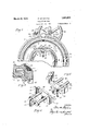
The invention has been shown in the drawings as applied to a vulcanizing mold for use in the manufacture of automobile tires, but the various features are not restricted to this specific embodiment. The mold includes a pair of opposed mold sections and 11,
Vwhich are jacketed in the usual manner to provide steam heating chambers 12 and 13, and said sections being respectively mounted on central supporting members 14 and 15 in the form of circular plates. The member 14 is held in xed position by a pair of posts 16 which extend upwardlyT from a base 17, while the member is carried by a pair of swinging arms 18 which are pivoted to the base at 19 below the mold. An angular olfset 20 at the lower portion of each arm 18 is so proportioned as to place thecenter of gravity of the swinging mold section 11 close to the pivotal center 19, rendering said arms 18 and their associated parts capable of easy movement in opening and closing the mold. The mold sections 10 and 11 are preferably detachable from the supporting members 14 and 15, whereby molds of dilie'rent sizes or different tread designs may be interchanged in a single machine frame, each mold section being provided with an inwardly eX- tending flange 21 of standardized proportions to lit upon annular seats 22 and 23 adjacent the peripheries of the supporting plates 14 and 15, and being fastened thereto by studs or bolts 24. Thus, the mold sections are capable of relative engagement or separation, as desired, and are capable of being locked together by means which will hereinafter be fully described.
The inner faces of theopposed mold sections 10 and 11V are respectively provided with the usual mold cavities 25 and 26 having lateral or cylindrical walls 27 which form seats for the bead portions of an unmounted tire 28 during the vulcanizing operation.. In order to facilitate the insertion of the tire within the mold, andits subsequent removal therefrom, novel means are provided for supporting a tire out of the mold cavities when the mold is open, said means functioning to strip the tire from the mold as it is opened.
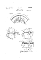
Referring particularly to Figs. 2, 3, 5 and 6, itwill be seen that the tire-supporting and stripping mechanism includes a pair of blocks 30 and 31, the block 3() being adapted to seat within arecess 32 in the mold section 10, while the block 31 is adapted to seat within a similar recess 33 in the mold section 11. T he recesses 32 and 33 intersect the mold cavities 25 and 26 by virtue ot 'the fact that the walls 27 are grooved as at 34 (Figs.
3 and 7 and at each of their ends the blocks 30 and 31 are provided with extensions 35 and 36, respectively. The upper surfaces of the extensions 35 and 36 are formed with cylindrical seat portions 37 which, when the mold is closed, constitute extensions of the annular walls 27 at their slotted portions 34, and outwardly of said portions 37 the eX- tensions 35 and 36 are provided with upwardly disposed ears 38, which also merge with the corresponding portions of the mold 4cavities and which are adapted to engage the outer sides of the beads or" the tire (Figs. 4 and rl`he body portion 39 of the block 30 is provided with a pair of spaced parallel supporting rods or dowels 40, said rods being slidably mounted in transverse apertures 41 in the stationary mold section 10. Extending downwardly from the lower edge of the body portion 39 is a pair of spaced ears 42, between which is pivoted, at 43, a latch member 44 having an arm 45, which latter extends toward the block 31 and is provided at its extremity with a hook 46, and with a downwardly extending arm 47 whose lower end is connected at 48 to a sliding link 49. rihe link 49 extends outwardly through a slot 50 in the supporting member 14 and is provided with an adjustable abutment 51 which, when the mold is closed, is spaced from a striking plate 52 secured to the mold section 10. i4 retractile spring 53 connects the extremity 54 of the link 49 with the striking plate 52 in such a manner as to eX- ert an inward force on the link 49 for the purpose of maintaining the latch member 44 in its proper position at all times.
1n order to automatically move the blocks 30and 31 with reference to their respective mold sections during the opening of the mold, the head 62 of the yoke 61 is connected nem-,cion
manner. A second arm 69 of the b'el-'l-ctnk- -A ispifovided at its ontiftinitynwiitli inller 79' which engages within a slotted lidad 7i @i linkx 72 which. pivot'ed at' 73 to base 17 lhepivotal center' at 7313s disposed out?k wardlyor" forwardly with -resple'oti'to the pivotal' center 19l of the' swinging n-loldsec'-V tion- 117 and the head 716i? they termed Wit-lr a' relatively long? slotl, the -pp'erend a purpose which Will her'einaal-terl be ex# plaiiiedf. The' liil;jr 72' Linder the inltlenc'e" ofY a coiled `spring 7T, 'Which lioz'inall-'yV tend-'s to drew' the link inwardly toward. tlie swingingarms 18, andthe-lendth' of saidv 'link may 'be adjll-ste'd as required by 'means of :1L-- turnbu'cl'nle connection 78 with its slot-- i ted head 7l) Extending snlistanta-lly pierpen'di-culaif' to the armV 69 and preferably i-n-Y v teg-ral4 therewith is a lug 8O having a threadedaperture for the reception odia-n adjustable screw 8l Which-may fhetlo'cled in its ad-jtlsted positionbyl me'ans'fif lock nuts 82,-
th'e arrangement bei-ng such-that latcerta'iil intervals' i-n the" eperationfof Vthe" device, the` -headof the adjustable screw 811Wil'l cotdc't 'ivith'rthe inner edgeof the head iiiembe'i" 7l o'l he lpivoted' link 72; In Fig 2,- tlie mold- 'isi's in closed lposition and; the Varioiis parts 'ofthe strippin'g-` mechanism fire Lshowninfthe 1i'ositioi'is Which"they occupy in thisl condition. The blocks 30 and 31 are Aseat-'ed Within their respectiyc recesses 32 and-'33 in abutting relation With respecttoeach other, the latch i4 enigagiiig' the 'pinA 6.0,l and' the abutment 5l lei-ngY 'spaced l'eyoififd-the outer side of the stri-king plate 52; It `will also he" noted that in thisV condition v*the pini `66y is practically at theibo't'tom 'of the" sloty y(i3, that the roller 'TOis at' the' uppere'nd yof the' widened portion 7576i theslo't 74.
In View of the fact that the m0-ld is lipl right, and that the movable mold 'section 11 swings downwardly, it will be an easy nia-t'- ter for the Operator t0' open and close the mold. The ease of peration may he' further" augmented by the provision of colin-teba-l# ancing mechanism 83, which 'includesa-ft'ele scopi@ rod section `84 having lits Lipper end pivoted vas at 85 to the ymemloer Vl5, `and its lower end sldfably receivdwithin tiibn# lar member' 86, Which in "turn is -i'ted 'Lett' 87, to the hase' 'ofthe'niaclilne.` 'Thetle-A Sco-pic'ally connected "portions 84 -nd '86 tre respestiV-Vely provided 'with collrsa" and 88 between which VaI compression spring' 89de?A coni-ined. The pivotalvc'enter'rgis' disposed 'D forwardly 'olf-tnt pivot lathe-:relay ijnnpen-j thermoldgfthe collar 87'Si approaches thev collar "88, thus-gradually increasing-L the' ree rod' section 84 and'resting; on the1 upper yand of .tubular member' 8'6" is `a smaller coil spring; 90? Whiohl acts a buffer; the arrangement bei'ijifg sushiA thatv as the mold section 11 rztelfxes predetermined peint iin its opening movementg' the collar 87 comesin Contact.' Witlfrthe'dpper' end of sai'dispring. 90 and' compressesfit 'dn-tilllitsi resistance, :coupled that of the spring. 89, i'ssulicient to'- overconi'ethe Weight of the' section 11 and its: associated' parts;
-lt: is necessary thatl the mold sections-hev firmly heldtogfetheif'to resist internal pres-i sui-e 'during the Vulcam'fzing; operation,l and to this end af locking ring 91 is rotatably moimted 'upon the Vfixed Vnfiol'd section 10,! sai-'d'rif1`gheling;l provided; With spaced in- C Wardlly extending; lugs- 92which are adapted to straddlefperipheral flanged-portions 93y and' '94" on the' ino'ld Sections i9: and l1 14espieotively.-'y Ilie flanges 93 and 9d` of the plurality spaced radial slots1j95* corre:
locking oisulflc-ent Width'tof clear saidlngs, the" slots ofthe' flanfge'- 93 r 'being out of'aliignmentwith theslots o'lange 94, to;
reference/tothe section 10,'- and in this con` dition the iilingril will bemainta'ine'd on the fined inoldqsettionllof by virtue of the inet that the Vslots`9`5' oni the- flanges 93 and 94 are respectively fontj of.- azliggninent. j The inner stiifffaoesfsthe'i'ltigs 9 9,f or the ont-er surfaces ofthe flanges .93 and 9456i botn slightlyl beveled or Wedge-shaped to render the same" easily" erigagable Aand to" firmly' clampfth'er moldsections'in locked-relation. On itsin- ,non peniplie'ryiandbetween the opposed lugs v 92, the fin-gl 911is pifovided *Withind flangeV 96' Whiehjfrnisga supporting race for a plurielity of dnd-friction rollers 97, sti-id rollers engaging n cylindrical surface .98V on the fixed mold section l0. The locking ring'm'ay be rotated by actu-ation of a hand wheel 99 Whicht'urns pinionlOOmesjliing" with a ,gear segment 101 which is carried by thelocki'ng ring; "The pinion lOOisA mounted on one .endo ali-shaft `102 which.Visujournaled-in ag hfc'let '103 secured to the fiXedmold sectin 10.l The` t'lier endlof'lthe, shaft c'ztrries al 'Slillder'ed coaplilngflOd andthe hand Wheel 99`,said -lind Wheelhaiiing' a cooperating shouldered coijlig' 105",i and capable'f parl' tial' .rotation Ywith l rference to the shaft vand sp"@ndi-ngiin number with the' lugs 92 of the. i
ffii) meinten 10d; 1 ,Thus therein n substantiel `baekrlas'liA or lost' motion between the wheel tn@ pinion :iooswlienbyi itis .pas
` for operating the screw, and
.- section.
sible to Obtain a hammer blow effect in r-l tating the ring 91. j
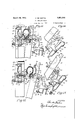
In Figs. 1, 8, 9 and 10, asimplified form of mold actuating mechanism has been illustrated whereby the mold sections may be forcibly drawn together as a tire is being inserted in the mold prior to .vulcanization, and whereby the mold sections may be easily and quickly separated after vulcanization. Such means comprises a` quick acting screw 106 which is rotatably secured in a sleeve 10'? pivoted at 108 to a pair of Vspaced ears 109, mounted on the fixed mold section 10. rlhe axis of the tothe axis of the screw 106 so that the screw may be swung upwardly to the position shown by dotted lines in Fig. 10. VMounted upon the screw 106 is a nut 111 which is internally threaded to cooperate Vwith the threads upon the screw 106, said nut being provided at its opposite ends with Vannular flanges 112 and 113. Rising from the movable mold section and preferably integral therewith, is a plate 114 having arecessed or bifurcated upper extremity 115, with which the nut 111 is adapted to cooperate as clearly shown in the drawings.
112 and 113 may be square, and adapted t0 be received with a reasonably snug lit in the bifurcated end v115 of said plate, and in this manner, the nut 111'is prevented from rotating as the screw 106 is turned. Any desired type of handle 116 may be provided it will be evident that as the screw is turned in one direction or the other, the nut 111 will be moved longitudinally with reference to the sleeve 107, and the movable mold section 11 .S will be correspondingly moved by virtue of the engagement ofeither of the flanges 112 ork 113 with the plate 114. ln opening the mold, it'may be initially broken by the actuation of the screw 106, as shown in Fig.
a 9, and after the mold-section 11 has been moved away from the mold section 10, the free end of the screw'106 may be swung up- .vardlj7 to the dotted-line'position shown in Fig. 10, after which said swinging mold section will easily open and actuate the tire stripping mechanism. Y
Steam or other heating fluid is supplied to the mold ackets 12 and 13 through suitable piping 119 and 120 respectively, rising from 'E a single supply pipe 121 which is anchored at 122 to a supporting bracket 123 on the base 1'?. The piping 120 includes a swivel joint 124 which is in axial alignment with the pivotal center 19 of the movable mold Condensation from within the mold jacket is drained throughpiping 125 and 126 connected at substantially the lowest points in the jacket, the piping 126 also including a swivel joint 127 in `axial alignment with the joint 124 and pivotal center pivot 108 is perpendicular rlfhe body port-ion of the nut 111 between the flanges- 19. While the V,jackets have been shown as supplied with the heating fluid at only one point and from a single source of supply, they can each be so supplied at a plurality of points fromeither one or more supply pipes, as is well known to those Well skilled in the art.
By way of recapitulation, the operation of the machine will now be described. Starting with the parts in position as shown in -v Fig. 2, and assuming that the tire 28 has been sufficiently vulcanized, the mold may be unlocked by rotating the hand wheel 99 and pinion 100, turning the locking ring 91 to the position shown in Fig. 1, wherein the lugs 92 are in alignment with the slots 95 in flange 94. By then rotating the handle 116 in a clock-wise direction (Fig. 1), the screw 106 and nut 111 will forcib'ly separate the mold sections swinging the section 11, its 20, and associated parts outwardly from the fixed section 10. At this stage in the operation, the two blocks 30 and 31 are being collectively held together by the latch under the free influence of its spring 53. [is the mold section 11 is then swung downwardly, the two blocks are moved outwardly with a positive action, being pulled away from the fixed section 10 to strip the tire therefrom and pushed away from the swinging section 11 `te stripv the tire from it at or about the same time. ln the operation of the parts, the blocks are drawn away from the lined mold section at a faster speed than that at which theyare operated away from the swinging mold section, due to the action of the link 2 which tends to turn the bellcrank lever counter-clockwise at the same time that the lever is being carried bodily in a clockwise direction by the movement of the swinging mold section.
As the opening movement of the mold section 11 continues, the abutment 51 comes in contact with the striking plate 52,7which arrests movement of the link 49 and thereby trips the latch 44, disconnectingthe block 31 from the block 30, as shown in Fig. 11. Further movement of the mold section 11, after the latch 44 has been tripped, results in further displacement of the block 31 from its recess 33, and finally in a downward movement lof the roller in the slotted head 71r lilhen the roller 70 reaches the shoulder 7 6 as shown in Fig. 12, the bell-crank 65 is given a quick movement in a counter-clockwise direction to complete the stripping of the tire from the movable mold section 11 and in view of the face that the blocks 30 and 31 have become separated, the tire may now be easily lifted out of the mold by the operator.
Continuing the opening movement, the roller 70 moves downwardly in the slot 7 4 and soon the head of the screw 81 abuts the inner edge of the .slotted head 71 of link 7 2 (Fig. 13) producing a tripping action by which the Cil bell-crank .is moved in'V a clockwise direc-V tion, reseating the block-31 inrecessf33, as-
shown in Fig. 14. During theopening movement of the mold' sectionv11fas.justdescribech the counter-balancing mechanism 83 hasbeen operating, the rod 811 having moved into the tubular member 86 compressing the spring' 89,
and the movement being `nally arrested by the buffer spring` 90. y
When the mold stands open, ityvill be a easy matter for the operator tof insert an unvulcanized tire4 preparatory to vulcanization,
it being onlynecessary to` place thetire in the mold cavity 26 Withthe 'corresponding bead to yengagement to properly confine the tire,
they may be locked in such relationship'by Arotation of the locking ring 91 to a position in Which its opposedlugs 921 straddle the solid portions of the flanges .93 and 94;.
As shovvn in several of the figuresv (seey particularly Figs. 2, 11 and 12) the two'mold seeti- ons 10 and 11 are provided at the inner peripheries of the tirecavities 25 and 26,'immediately adjacent the bead seats 27.vvith oppositely disposed beveled or cone-shaped surfaces25a and 26?,'respectivelyTwbich are adapted to engage the inner or beadf'edgesfof the tire and center and guide the same to its seat inthe tvvo cavities as the mold is closed in the event that the tire is improperly .placed in the mold section 26 or becomes 'displaced' therefrom prior to the closingof the mold. The angle or extent of the beveled surfaces may be greater or less than that illustrated, so long as the surfaces are capable of performing their required function.
From the foregoing, it Will be evident that an improved vulcanizing mold of eXtreme simplicity has been produced,j with which tires may be expeditiously vulcanized with a minimum amount of labor, and that the mold may be easily opened and closed, quick-` ly locked in closed position; and the Work Will be automatically stripped from the moldl cavities as the mold is opened. Obviously, changes may be resorted to in the details'of construction and arrangement of parts, and the right is herein reserved. to make Vsuch changes as fall Within the scope of the Vappended claims, Without departing from the A spirit of the invention.
Having thus described my invention, vvhat I claim is: 1. A Vtire vulcanizingV mold including, in
combination, a. relatively fixed mold section,
a movable mold section, a Atire supporting member mounted With-each mold section,said tire supporting members being movabl-ewith 'reference to their; respective ymold sections, Vmeans for vholding the supporting members collectively` with the', .tireias the `mold is opened, and means actuatedby the opening movement to' shift the tire supporting mem-V to lautomatically lstrip the tire. f
"7d bersfrom bothfthe mold-sections, whereby Y 2. A; tire vulcanizingA mold including,;in l
combinatiom. agr'elatively xed mold section, a movable mold section, apair ofy t1resup `porting members eachmount-ed with onel of the mold sections and adaptedfto engageone bead of ,they tire,-said*tire supportingmembers being axially movable With reference to their respective mold sections means for yholding the supportingfmembers collectively V` d'uring the. initial opening movement ofy the movable mold.-y section, means for automaticallyl shifting the supportingmembersrelative to both mold sections vvher'ebyf tostrip the tire therefrom, and means for separating thev supporting m-embersto release the vulcanized tire.
' 31 Inatire'vulcanizingmold,az'iicedmold Y sectiona movable mold section hin-ged with reference thereto, the` opposed faces ofvsaid mold sections bei-ngprovided vvithfrecesses, and tire stripping' means associated with the moldaa'nd automatically" actuated by1 they movement ofthe movable vmold section,s aid strippingme'ansfincluding a pair ofopposed Y' blocksxadaptedto be seate'din said recesses n whenthe moldfis closed and to-engag'e the beads of the tire, means forfcollectivelyholding the opposed'v blocks and-the tirewas the moldis openedand means forfseparating :the
. blocks toreleasethetii'e as the openingmoyej ment'continues;l 5 a 1 jp 41.A In "zr/tira vulcanizing f mold, a pair of opposed 'mold' sections' hinged? with yreference ioo tionsbeing providedwithfrnoldr cavities and tire, and means forcollectively moving the pairl of .blocks .and the tire-with reference to both ofthe. moldssectionsras the mold is opened.. l. v f
5;V `Infa vtire vulcanizing -mol-d,ra pair of opposedfmold Sections hinged With reference t'o eachgothenthe opposed faces ofsaid sections being Yprovided vvith mold ,cavities and recesses intersecting `tli`ecavities,`a pair of blocks adapted to support a tire when. the` mold is open and to beV seated vin said .recessesl vWhen'the mold'is closed, portions -of said blocks forming continuationsof-the mold cavitiesfto engage'the opposite sides ofthe tire, means for collectively moving the pair of blocks andiV thetire with reference toboth ofthe' mold sections the` mold yis opened,
' gagement,
and meansfor separating-the blocks from each other to release the vulcanized tire, said separating means being automatically actuated by the continued opening movement-oi the mold. Y
6; In a tire vulcanizing mold, a relatively fixed mold section, a movablemold. section hinged with reference thereto, the opposed Jfaces of said sections being provided with mold cavities and recesses intersecting the cavities, a pair of blocks adapted to support a tire when the mold is open andto be seated in said recesses when the mold is closed,.por tions of said blocks forming continuations of the mold cavities to engage the opposite sides ofthe tire, a latch for normally securing the pair of blocks together, means for collectively moving the blocks and the-vulcanized tire away from their seats in both mold sections as the mold is opened, and means for automatically separating the blocks from each other to release the tire as the opening movement progresses. Y i
7. In a vulcanizing mold, a pair otv mold sections capable ot relative separation or engagement, spaced peripheral locking members on one of the mold sections, a cooperating locking ring rotatably mounted on the other mold section, means for actuating said locking rings, and independently operable means including a screw-threaded element for drawing the two mold sections together and forcing them apart when the ring is in unlocked position.
sections capable of relative separation or enspaced peripheral locking members on one of the mold sections, a cooperating locking ring rotatably mounted on the other mold section, means for actuating said locking ring, and independently operable means for drawing the mold secti ons together and forcing them apart when the ring` is in unlocked position, said means including` a screw pivoted at one of its ends to one of the mold sections, a threaded nut mounted on the screw, and means cn the other mold section for engaging the nut to prevent its rotation when the screw is turned.
9. In combination with a pair of vulcanizing mold sections having opposed. mold cavities, each provided with a work stripping member in the form .of a displaceable wall portion of the corresponding cavity, and means operated by the opening of the mold for automatically actuating .both said displaceable portions to strip the work from the opposed cavities.
10. In'combination witha pair of vulcanvizing mold sections having opposed mold cavities each provided with a displaceable wall portion, means operated by the opening of the mold for automatically actuating said displaceable Wall portions to strip the signature hereto. 8. In a vulcanizing mold, a pair of mold Y work with a differential movement from both the mold sections.
11. In combination with a pair of vulcanizing mold sections having opposed mold cavities, worlr stripping means including displaceable portions means for con]l ointlydisplacing said portions of the cavity walls to strip the work therefrom with a differential movement as the mold is opened.
l2. In a -tire vulcanizer, the combination of a pair of separable mold sections having opposed annular tire cavities with seats for the tire beads, a pair of tire stripping members forming displaceable portions of the bead seats ofthe respective mold sections, and means for automatically actuating the stripping members as the mold is opened to dislodge the tire from the opposed cavities 0i the mold sections.
13. In a tire vulcanizer, the combination of a pair of mold sections having opposed annular'tire cavities with seats for the tire beads, one of said sections being hinged with reference to the other, ping members carried by the respective mold sections and forming displaceable portions of the bead seats therein, and means act-uated bythe opening movement of the hinged mold section Afor actuating the stripping members to dislodge the tire from the opposed cavities.
In testimony whereof, I have aliixed my PETER :on Miirrra.
oic the cavity walls, and
a pair of tire strip-
Priority Applications (1)
| Application Number | Priority Date | Filing Date | Title |
|---|---|---|---|
| US160174A US1851003A (en) | 1927-01-10 | 1927-01-10 | Vulcanizing mold |
Applications Claiming Priority (1)
| Application Number | Priority Date | Filing Date | Title |
|---|---|---|---|
| US160174A US1851003A (en) | 1927-01-10 | 1927-01-10 | Vulcanizing mold |
Publications (1)
| Publication Number | Publication Date |
|---|---|
| US1851003A true US1851003A (en) | 1932-03-29 |
Family
ID=22575828
Family Applications (1)
| Application Number | Title | Priority Date | Filing Date |
|---|---|---|---|
| US160174A Expired - Lifetime US1851003A (en) | 1927-01-10 | 1927-01-10 | Vulcanizing mold |
Country Status (1)
| Country | Link |
|---|---|
| US (1) | US1851003A (en) |
Cited By (1)
| Publication number | Priority date | Publication date | Assignee | Title |
|---|---|---|---|---|
| US2627375A (en) * | 1948-01-05 | 1953-02-03 | Weyerhaeuser Timber Co | Separation of bark components |
-
1927
- 1927-01-10 US US160174A patent/US1851003A/en not_active Expired - Lifetime
Cited By (1)
| Publication number | Priority date | Publication date | Assignee | Title |
|---|---|---|---|---|
| US2627375A (en) * | 1948-01-05 | 1953-02-03 | Weyerhaeuser Timber Co | Separation of bark components |
Similar Documents
| Publication | Publication Date | Title |
|---|---|---|
| US3097394A (en) | Tire curing press | |
| US3787262A (en) | Tire building drum | |
| US3854853A (en) | Segmental mold | |
| US1851003A (en) | Vulcanizing mold | |
| US2345172A (en) | Tire retreading apparatus | |
| US2231254A (en) | Recapping and retreading mold | |
| US2291506A (en) | Vulcanizing press | |
| US2272231A (en) | Retreading vulcanizer | |
| GB1559772A (en) | Pneumatic tyre manufacture | |
| US2778060A (en) | Tire curing press | |
| US1852557A (en) | Vulcanizing mold | |
| US2290630A (en) | Vulcanizing press | |
| US1984768A (en) | Vulcanizer | |
| US2574171A (en) | Tire side wall mold | |
| US1526594A (en) | Apparatus for manufacturing tires | |
| US1760944A (en) | Tire-retreading mold | |
| US1756266A (en) | Mold | |
| US2254926A (en) | Device for supporting tires in vulcanizers | |
| US1863604A (en) | Vulcanizing mold | |
| US2320778A (en) | Tire vulcanizing apparatus | |
| US1756058A (en) | Tube vulcanizer | |
| US1662035A (en) | Retread mold for tires | |
| US1940582A (en) | Vulcanizing press | |
| US1697460A (en) | Vulcanizer | |
| US1812792A (en) | Vulcanizing apparatus |