US185048A - Improvement in grain-drills - Google Patents
Improvement in grain-drills Download PDFInfo
- Publication number
- US185048A US185048A US185048DA US185048A US 185048 A US185048 A US 185048A US 185048D A US185048D A US 185048DA US 185048 A US185048 A US 185048A
- Authority
- US
- United States
- Prior art keywords
- bar
- attached
- grain
- cross
- pivoted
- Prior art date
- Legal status (The legal status is an assumption and is not a legal conclusion. Google has not performed a legal analysis and makes no representation as to the accuracy of the status listed.)
- Expired - Lifetime
Links
- 238000005266 casting Methods 0.000 description 5
- 239000010813 municipal solid waste Substances 0.000 description 2
- FAPWRFPIFSIZLT-UHFFFAOYSA-M Sodium chloride Chemical compound [Na+].[Cl-] FAPWRFPIFSIZLT-UHFFFAOYSA-M 0.000 description 1
- 239000002184 metal Substances 0.000 description 1
- 239000011780 sodium chloride Substances 0.000 description 1
Images

Classifications
-
- A—HUMAN NECESSITIES
- A01—AGRICULTURE; FORESTRY; ANIMAL HUSBANDRY; HUNTING; TRAPPING; FISHING
- A01C—PLANTING; SOWING; FERTILISING
- A01C5/00—Making or covering furrows or holes for sowing, planting or manuring
- A01C5/06—Machines for making or covering drills or furrows for sowing or planting
Definitions
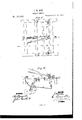
- Figure 1 is a top view of a part of my i1nproved grain-drill.
- Fig. 2 is a detail section of the same, taken through the line a: m, Fig. 1.
- the object of this invention is to furnish an improved grain-drill, which shall be so constructed that it will not clog with trash, will adjust itself to an uneven surface of ground, will sow the seed evenly and uniformly, and may be easily operated.
- the invention consists in the combination of the pivoting castings, the pivoted standards, the cutter, and the conductor-spout with the adjustable crossbar; in the combination of the loop or clevis, the draw-chain, the double spring, and the pivoted cross-bar with the standard and cutter and with the frame; and in the combination of the rigid lever, the pivoted lever, and the locking-pin with the pivoted bar to which the springs are attached, and'with the tongue, as hereinafter fully described.
- A represents the frame of the drill, to the side bars of which are bolted two slotted castings, B.
- the slots of the castings B are secured, by bolts 1), the ends of a cross-bar, 0, several holes being formed in thecastings B, to receive the bolts b, so that the cross-bar 0 may be adjusted higher or lower, as may be desired.
- To the bar 0 are bolted castings D, as many as desired, to lugs, upon the rear side of which are pivoted, by a bolt, d, the upper end of the standards or bars E.
- the run ners or cutters F To the lower end of the standards E are secured the run ners or cutters F, the forward ends of which are curved forward, upward, and rearward, and are attached to the standards E, so that there is no point or end for trash to catch
- the part of the cutter F in the rear of the standard E is forked, and the upper parts of its wings are inclined outward, or area little wider apart than the lower parts, to pack the sides of the furrow, and prevent them from falling in before the seed has been fairly deposited.
- a tube or spout, G To the rear side of the standard E is attached a tube or spout, G, to receive the seed from the hose or spouts leading from the grain-box, and conduct it to the bottom of the furrow within the forked rear end of the cutter F.
- the standard E is made of such a-length, and the cross-bar O is so adjusted, that the said standard E may have a rearward inclination when at work.
- In the middle part of the standard E above the end of the cutter F, are formed a number of holes, to receive a clevis or loop, H, to which is attached the end of the draft-chain I, so that the point of draft attachment may be raised and lowered, as may be required.
- the forward end of the draft-chain I is attached to the lower end of the spring. J, the upper end of which is attached to the forward .side of the cross-bar K.
- the spring J is reenforced by a spring, L, which has a loop attached to its lower end, through which the lower part of the spring J passes.
- the upper end of the spring L is attached to the rear side of the cross-bar K.
- pivots M which work in bearings N, attached to the upper side of the side bars of the frame A, so as to pivot the said cross-bar eccentrically to said frame.
- a lever, O which extends back into such a position that it may be conveniently reached and operated by the driver to bring the cutter F into working position after having been swung back to raise it from the ground.
- a second lever, P to the forward end of which is pivoted a pin, Q, which passes down through a hole in the bar K, and enters a hole in the tongue R, attached to the lower side of the cross-bars of the frame A.
- the tongue may have several holes formed in it-to receive the pin Q, and its upper side is concaved, and faced with metal, to allow the cross-bar K to turn upon its pivots and to prevent wear.
- clevis, loop, or book, S To the rear side of the standard E is attached a clevis, loop, or book, S, to which is attached the end of the chain T.
- the other end of the chain T is connected with a bar or lever of the rear part of the frame A, for convenience in raising the cutter F awayfrom the ground, when desired.
Landscapes
- Life Sciences & Earth Sciences (AREA)
- Soil Sciences (AREA)
- Environmental Sciences (AREA)
- Soil Working Implements (AREA)
Description
I. R. ROE.
GRAIN-DRILL.
Pawn ted Dec. 5, 1876.
ATTBBNEYS.
THE GRAPHIC CO-ILY lvrrnn STATES PATENT FFICE,
JAMES R. Ron, OF FAIRVILLE, MISSOURI.
IMPROVEMENT m GRAlN-DRlLL S.
Specification forming partof Letters Patent No. 185,048, dated December 5, 1876 application filed August 14, 1876.
I upon.
To all whom it mdy concern:
Be it known that I, JAMES R. ROE, of Fairville, in the county of Saline and State of Missouri, have invented a new and useful Improvement in Grain-Drills, of which the following is a specification:
Figure 1 is a top view of a part of my i1nproved grain-drill. Fig. 2 is a detail section of the same, taken through the line a: m, Fig. 1.
Similar letters of reference indicate corresponding parts.
The object of this invention is to furnish an improved grain-drill, which shall be so constructed that it will not clog with trash, will adjust itself to an uneven surface of ground, will sow the seed evenly and uniformly, and may be easily operated.
The invention consists in the combination of the pivoting castings, the pivoted standards, the cutter, and the conductor-spout with the adjustable crossbar; in the combination of the loop or clevis, the draw-chain, the double spring, and the pivoted cross-bar with the standard and cutter and with the frame; and in the combination of the rigid lever, the pivoted lever, and the locking-pin with the pivoted bar to which the springs are attached, and'with the tongue, as hereinafter fully described.
A represents the frame of the drill, to the side bars of which are bolted two slotted castings, B. In the slots of the castings B are secured, by bolts 1), the ends of a cross-bar, 0, several holes being formed in thecastings B, to receive the bolts b, so that the cross-bar 0 may be adjusted higher or lower, as may be desired. To the bar 0 are bolted castings D, as many as desired, to lugs, upon the rear side of which are pivoted, by a bolt, d, the upper end of the standards or bars E. To the lower end of the standards E are secured the run ners or cutters F, the forward ends of which are curved forward, upward, and rearward, and are attached to the standards E, so that there is no point or end for trash to catch The part of the cutter F in the rear of the standard E is forked, and the upper parts of its wings are inclined outward, or area little wider apart than the lower parts, to pack the sides of the furrow, and prevent them from falling in before the seed has been fairly deposited. To the rear side of the standard E is attached a tube or spout, G, to receive the seed from the hose or spouts leading from the grain-box, and conduct it to the bottom of the furrow within the forked rear end of the cutter F.
The standard E is made of such a-length, and the cross-bar O is so adjusted, that the said standard E may have a rearward inclination when at work. In the middle part of the standard E, above the end of the cutter F, are formed a number of holes, to receive a clevis or loop, H, to which is attached the end of the draft-chain I, so that the point of draft attachment may be raised and lowered, as may be required.
The forward end of the draft-chain I is attached to the lower end of the spring. J, the upper end of which is attached to the forward .side of the cross-bar K. The spring J is reenforced by a spring, L, which has a loop attached to its lower end, through which the lower part of the spring J passes. The upper end of the spring L is attached to the rear side of the cross-bar K. To the upper side of the ends of the cross-bar K are attached pivots M, which work in bearings N, attached to the upper side of the side bars of the frame A, so as to pivot the said cross-bar eccentrically to said frame. To the cross-bar K is rigidly attached a lever, O, which extends back into such a position that it may be conveniently reached and operated by the driver to bring the cutter F into working position after having been swung back to raise it from the ground. To the lever Ois pivoted a second lever, P, to the forward end of which is pivoted a pin, Q, which passes down through a hole in the bar K, and enters a hole in the tongue R, attached to the lower side of the cross-bars of the frame A.
The tongue It may have several holes formed in it-to receive the pin Q, and its upper side is concaved, and faced with metal, to allow the cross-bar K to turn upon its pivots and to prevent wear.
To the rear side of the standard E is attached a clevis, loop, or book, S, to which is attached the end of the chain T. The other end of the chain T is connected with a bar or lever of the rear part of the frame A, for convenience in raising the cutter F awayfrom the ground, when desired.
Having thus described my invention, 1
claim as new and desire to secure by-Letters Patent- 1. The combination of the castings Dythe pivoted standards E, the cutter F, and the conductor-spout G with the adjustable crossbar 0, substantially as herein shown and described.
2. The combination of the loop or clevis H, the draw-chain I, the double spring J L, and
the pivoted cross-bar K with the standard and cutter E E, and with the frame A, substantially as herein shown and described.
' -3r -'1he combination of the rigid lever O, the
pivoted lever P, and the locking-pin Q with the pivoted bar K, to which the springs J L are attached, and with the tongue R, substantially as herein shown and described. 7
a J. R. ROE.
Witnesses: V
JAMES D. CAHILL, Anrsson Fom).
Publications (1)
| Publication Number | Publication Date |
|---|---|
| US185048A true US185048A (en) | 1876-12-05 |
Family
ID=2254453
Family Applications (1)
| Application Number | Title | Priority Date | Filing Date |
|---|---|---|---|
| US185048D Expired - Lifetime US185048A (en) | Improvement in grain-drills |
Country Status (1)
| Country | Link |
|---|---|
| US (1) | US185048A (en) |
-
0
- US US185048D patent/US185048A/en not_active Expired - Lifetime
Similar Documents
| Publication | Publication Date | Title |
|---|---|---|
| US864561A (en) | Seed-drill. | |
| US96322A (en) | Improvement in combined cultivator and seed-planter | |
| US653833A (en) | Seeder. | |
| US641718A (en) | Grain-drill. | |
| US155419A (en) | Improvement in corn-cultivators | |
| US568442A (en) | Potato-planter | |
| US150338A (en) | Improvement in road-scrapers | |
| US290233A (en) | Potato-planting attachment for corn-planters | |
| US140551A (en) | Improvement in wheel-plows | |
| US233934A (en) | Combined cultivator and seeder | |
| US184583A (en) | Improvement in wheel-plows | |
| US791161A (en) | Cotton-planter. | |
| US1169945A (en) | Grain-drill. | |
| US855678A (en) | Plow and seeder. | |
| US208015A (en) | Improvement in corn-planters | |
| US672476A (en) | Grain-drill. | |
| US389067A (en) | foster | |
| US136062A (en) | Improvement in gang-plows | |
| US424823A (en) | Road-scraper | |
| US711274A (en) | Fertilizer-distributer. | |
| US191043A (en) | Improvement in sulky-harrows | |
| US148729A (en) | Improvement | |
| US174993A (en) | Improvement in corn-planters | |
| US59283A (en) | Improvement in seeding-machines | |
| US299905A (en) | brooks |