US1850403A - Mechanism for drilling angular channels - Google Patents
Mechanism for drilling angular channels Download PDFInfo
- Publication number
- US1850403A US1850403A US567630A US56763031A US1850403A US 1850403 A US1850403 A US 1850403A US 567630 A US567630 A US 567630A US 56763031 A US56763031 A US 56763031A US 1850403 A US1850403 A US 1850403A
- Authority
- US
- United States
- Prior art keywords
- housing
- units
- drill
- drilling
- drill bit
- Prior art date
- Legal status (The legal status is an assumption and is not a legal conclusion. Google has not performed a legal analysis and makes no representation as to the accuracy of the status listed.)
- Expired - Lifetime
Links
Images


Classifications
-
- E—FIXED CONSTRUCTIONS
- E21—EARTH DRILLING; MINING
- E21B—EARTH DRILLING, e.g. DEEP DRILLING; OBTAINING OIL, GAS, WATER, SOLUBLE OR MELTABLE MATERIALS OR A SLURRY OF MINERALS FROM WELLS
- E21B7/00—Special methods or apparatus for drilling
- E21B7/04—Directional drilling
- E21B7/06—Deflecting the direction of boreholes
- E21B7/061—Deflecting the direction of boreholes the tool shaft advancing relative to a guide, e.g. a curved tube or a whipstock
Definitions
- My invention relates to drilling tools and more particularly to tools for drilling angular channels; and the object is to provide apparatus for drilling wells which is pro- Vided with means for making angular channels from the vertical opening in the earth known as the well.
- the object is to make channels extend out through the surrounding area from the vertical well.
- Another object is to provide positive means for drilling a given or predetermined angle from the vertical opening.
- An advantage of this invention is that the producing sands or reservoir may be penetrated at various angles from the vertical hole or opening in the earth.
- Another advantage of this invention is that several channels may be drilled angularly fromthe vertical opening at approximately the same level without removing the apparatus from the well.
- Another advantage of this invention is that the various angular channels may be directed from the vertical opening by one deflector unit which is controllable from the top of the well. Another advantage is that there is provision made for determining the drill bit pressure in angular drilling. Another advantage is that means are provided to flush out the drill cuttings from the angular channels without removing the drilling tools.
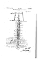
- Fig. 1 is a vertical section of a well casing
- Fig. 2 is a vertical section of a portion of the drilling tool, showing the drill bit pressure indicating mechanism.
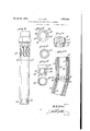
- Fig. 3 is a vertical section of the lower end of the drilling tool and drill bit. showing the ports for pneumatically operating the bit.
- Fig. 4 is a vertical section of the deflector and its housing, showing the guide for the drilling tool and anchoring means for the housing.
- Fig. 5 is a vertical section of a portion of the deflector housing taken at right angles to Fig. 4, showing the lateral opening in the housing.
- Fig. 6 is a plan view of the ratchet for actuating the deflector.
- Fig. 7 is a vertical section of the same, showing the retaining ring for the rotor of the ratchet.
- Fig. 8 is a plan view of the retainer for the ends of the guide arms that'pass through the ratchet Fig. 8A is a top plan view of the rotor with the guide arms passing therethrough.
- Fig. 9 is a perspective view of the guide and slot member which is made integral with theldeflector housing for directing the drill too
- Fig. 10 is an enlarged'view of one of the guide arms that pass through the ratchet.
- Fig. 11 is a plan view of the same, showing the extent of its spiral curvature from the top to the bottom.
- Fig. 12 is a detail view of the outer housing or casing of one of the flexible drill units.
- Fig. 13 is an inverted plan view of the same.
- Fig. 14 is a detail view of the center element of one of the flexible drilling units, showing the enlarged portion at the top thereof to form the upper outer portion of the unit.
- Fig. 15 is an inverted plan view of the same.
- Fig. 16 is a side view of the inner element of one of the drill units, shown partly in section and illustrating the ball joint.
- Fig. 17 is a plan View of the ball joint.
- Fig. 18 is a sectional view of the inner element taken on the line 18-18 of Fig. 16.
- Fig. 19 is a detail view of the lower portion of the inner element, showing the cut out portion formed to conform with the inner periphery of the ball joint.
- Fig. .20 is a sectional view of the same taken on the line 2020 of Fig. 19.
- Fig.21 is a vertical section of the ball joint, showing the locking lug.
- Fig. 22 is a vertical section of a joint of the drill stem, showing the joint locked in an angular drilling position.
- F1 23 is'an inverted plan view of the drillbit, shown partly in section, with a number of cutting b ades removed.
- Fig. 24 is "a plan view of the pneumatic motor for rotating the drill bit.
- Fig. 25 is a plan view of the earing connecting the motor with the drill it.
- Fig. 26 is a detail view of a portion of the ring and the lower housng therefor, owing the housing in section and the housing teeth to engage and 0 rate the face glutch of the rotatlng rifle er of the drill
- Fi 27 is a plan view of the valve controlling t e pneumatic element directed upon and actuating the piston for tamping the drill bit.
- Fig; 28 is a side elevation of the valve shown partly in section.
- Fig. 29 is a plan view of the rotating rifle bar, showing the face clutch for receiving the lower end of the rotating internalgear housing.
- Fig. 30 is a side elevation of the upper portion of the rotating rifle bar of the drill t, showing the drill bit piston positioned thereon and in section.
- Fig. 31 is an inverted plan view of the lower end of the rifle bar, showing the bar Zplined for longitudinal action in the drill Fig. 32 is a vertical section of the flush valve for diverting the power medium from the drill bit mechanism into the well for flushin the drilled cuttings out of the drilled channeis or hole.
- Fi 33 is a lan view of the same, showing t e side wa same in cross section.
- Fig. 34 is a vertical section of a well or deflector housing, showing the drill tool penetrating one of a plurality of an lar channels projecting from the vertical ole.
- Fig. 35 is a sectional view of the motor casing taken on the line 35-35 of 24.
- Fig. 36 is an enlarged side elevation of the motor for actuating the drill bit.
- My invention relates to the operating end 7 or drilling endof the drill stem and the power element is supplied to the drill mechanism through.
- This element may be air, gas or an other suitable element that isforoed throug the drill stem 2 to the flexible tube 1.
- Fig. 4 shows the upper extent of the flexible tube where it registers with the drill stem 2.
- the drill stem tubing 2 will extend down from the top of the well to the flexing units A.
- a joint 3 is interposed between the drill stem tubing 2 and the first flexing joint A.
- the joint 3 is provided with perforations 5 for the escape of the exhaustower element from the drill bit motor and other working parts.
- the joint 3 func tions as the positioning elementfor the drill stem so that the flexing direction of the units A will aline with the deflector and the deflector housing opening.
- the joint 3 is provided with a plug 3' integral with the upper portion'thereof and this lug is provided with a packing gland 4' which receives and secures the upper end of the tube 1.
- a deflector housing 6 When this device is used in a vertical hole or well, a deflector housing 6 is inserted into the well and extends from the top of the well to the bottom, or it may be set as a liner with suflicient number of joints to give the required weight and length for the stationary guide and to serve as an anchorage in the well. If set as a liner it may be actuated with the ordinary trip spear ona line (not shown).
- the deflector housing 6 is elevated and lowered to change the direction of deflector of the drill units.
- the housing 6 is provided with anchor points or engaging members 7 at the bottom thereof to project into the ground at the bottom of the hole.
- the anchor points 7 are provided with a retainer member 8 in which they are anchored and this retainer member 8 is provided with an upwardly projecting housing 9 screwed and secured thereto.
- the deflector housing 6 telescopes over the housing 9.
- the housing 6 is provided with a deflector 12 which is rigidly positioned therein and placed in the housing 6 at any required position above the bottom of the vertical hole for directing the drillin mechanism at an angle from the vertical.
- he deflector housin is provided with an opening 11 in the side fiiereof and opposite the deflector member 12 for the passage of the drilling units A for making angular channels form the vertical opening or well.
- the deflector member 12 is cylindrical at its bottom rtion to conform with the deflector housing 6 and provided with an elongated curve or an le 13 at the top thereof for deflecting the rilling unit through the openingll.
- Means are provided in the bottom of the deflector 12 for causing the deflector to be revolved when the deflector housing 6 is lowered.
- 'A ratchet member is laced in the upper portion of the anchor ousing' 8, see Fig. 4, to receive and ide directin arms or rotating arms 14.
- e ratchet wheel or rotor 15 is provided with a housing 16 which is screwed to the upper portion of the anchor housing 9.
- the housing 16 is provided with A teeth 17 on the inner periphery thereof to be engaged by pawls 18 which are carried by the rotor 15.
- the pawls 18 or dogs are each held in engagement with the teeth 17 of the housing 16 by means of aplunger 19 which reciprocates' in an opening in the rotor 15.
- a retainer ring 21 is screwed into the housing 16 for holding the rotor in working relation with the teeth 17 of the housing 16.
- the rotor 15 is provided with slots 22 for the passage therethrough of the directing arms 14.
- the rotor is provided with a center opening 23 for the passage therethrough of a directing arm retainer stem 24.
- the arm or stem 21 is made rigid with the deflector member 12 and projects downwardly therefrom.
- the arm or stem 24 is provided with collars-25 and 26 for'holding the top and bottom respectively of the directing arms 14.
- the stem 24 is made of sufficient size and strength to hold the di- 15 causing the rotor to revolve independent of the teeth 17 of the rachet housing 16.
- the rotor 15 will be held against rotation by the engagement of the pawls 18 with the teeth 17 of the rachet housing 16 thus causing a rotation of the housing 6 and its deflector 12 to the extent equivalent to the spiral twist or longitudinal form of the directing arms 14.
- the collars 25 and 26 cooperate with the stem 24 to hold the directing arms 14 rigid with the deflector 12 and housing 6. 'It is apparent that the rotation of the housing 6 only extends to that portion below the swivel joint.
- a stationary direction means is provided in the housing 6 for alining the drilling units with the deflector angle 13.
- This device is positioned'above the deflector 12 at a suflicient height for its length to correspond with the flexing units A or extend to a greater lengththan the total length of all the flexing units used.
- This device consists of an inner liner 27 which is maderigid with the deflector housing 6 and provided with a top rim 28 which is cut to slope from a tip 29 down to and terminating into a slot 30.
- the tip 29 is positioned in the housing 6 directly above and in a central line with the opening 11 of the housing 6. This causes the projection'31 on the joint 3 tobe directed into the slot 30 by following the rim 28 as the drilling units are being lowered into the housing 6,
- a leaf spring 32 is mounted on the outer periphery of the jint 3 so as to resiliently engage the inner periphery of the liner 27 and hold the joint 3 and the flexing units A centrally in the stationary guide to make the traveling guide or lug 31 ride the top flange 28 of the stationary guide and into the slot 30 of the stationary guide 27.
- Additional stationary guides 33 are added to the stationary guide 27 by positioning them under the stationary guide 27 so that there may be a continuation of the slot 30 to a suflicient depth in the well to insure perfect alinement of the flexing units A with the opening 11 of the housing 6.
- the directing arms 14 flector 12 may be formed with a suificient spiral to give a predetermined part of a complete turn to the housing 6 as the housing is lowered.
- the arms 14 are providedwith a straight portion 34 which allows longitudinal movement of the housing 6 without a rotary motion. This allows for the longitudinal stretch of the line giving a neutral action in the raising and lowering of the housing 6
- the portion 34 of the arms 14 are parallel with the arm 24.
- Each of the flexing units A are provided with ball joints 35 so as to give the necessary turn to the units as they are deflected in their downward movement through the 0 ening 11 of the housing 6.
- the hollow all joints 35 are each made integral with the top of each unit A, see Fig. 16.
- the ball joint is made integral with the last unit A or drill bit unit by means of bolts 36.
- the joint 35 is cast integral with the inner element or tubing 46 of the unit.
- the lower part of the joint is provided with an opening 38 the diameter of which is equivalent to the inner periphery of the tube 46, and the upper portion of the ball joint is provided with an enlarged opening 40 which terminates at its base in a shoulder 41.
- the side of the opening 40 is provided with flat side portions 39 ositioned opposite each other to act as a. caring for the lower portion 42 of the'next unit above.
- the lower portion 42 of the member 37 is formed to conform with the opening 40 of the ball 35.
- a portion of the part 42 is cut away so as to allow the necessary swing of each unit A in making the angular channel to the vertical opening in the earth.
- This part 43 see Figs. 19 and 20,
- the units A are provided with an outer shell 44, a center element'45, and an inner tube 46 all of which are pinned together.
- the lower end of the outer shell 44 is formed to fit over the ball joint 35 and the upper end extends approximately to the next ball joint above.
- the center element 45 is enlarged. at its upper portion and forms the outer shell from the upper end of the member 44 up to and surrounding a portion of the upper ball joint 35, see Fig. 22, leaving a space between the member 44 and the joint 35 to receive the curved portion of the outer shell 44 of the next unit above.
- the cut-away portion of the lower end of the inner element 45 allows only one angle of: fiexion of the units A.
- Some of the ball joints of the units are provided with locking means for holding the unitswhen they are turned at angles to each other or flexed.
- the locking means consists of a lug 47 which is rigidly anchored on the shoulder 41 in the opening 40 of the balls 35. This lug 47 is anchored in the ball joints 35 and are portioned adjacent to the slant 13 of the deflector 12 when in operative position.
- the inner element 46 is provided with an elongated leaf spring 48 the upper end of which is rigidly attached to the inner element 46.
- .Alongitudinal slot 49 is made in the inner periphery of the inner element 46 to receive the spring 48.
- the lower end of the spring 48 is provided with an extension 50 which engages the lug 47.
- This locking means maybe used on only the lower unit or drill bit unit. or it may be used on any number of the joints 35 of the units A.
- the lower unit or the drill bit unit contains a motor for rotating the drill bit and a reciprocating piston for tamping the bit.
- the piston gives a forward movement to the rotary drill bit when the power element is forced through theflexible tube 1.
- the drill bit motor is provided with a housing which consists of a base plate 51, side walls 52 and a top 53.
- a vertical drive shaft '54 projects through the top plate 53 and through the base 51 down to a sufficient length below the base plate 51 to carry av drive pinion 55 which'is rigidly attached to the lower end of the shaft 54.
- Vanes 56 are carried by a rotor 56 which is shaft 54 by 6 means of a key 57. It is apparent that Vanmade on the inner periphery of the housings.
- the pinion 55 meshes with and drives a set of gears 62.
- the gears 62 are provided with shafts 63 made integral therewith and journaled in end plates 64.
- the gears 62 mesh with the teeth 59 of the stationary housing 58 which causes the gears 62 to be revolved around the pinion 55.
- the shafts 63 are each provided with gears 65 rigidly attached thereto and positioned below the gears 62.
- the gears 65 mesh with the teeth 61 of the rotary housing 60 and drives the housing 60.
- the hous1ng 60 is provided with a face clutch 66 on the lower end thereof which engages and drives a clutch 67 which is made integral with the up er end of the rotating rifle bar 68 of the drill bit.
- the rifle bar 68 is provided with a bearing 69 for holding the clutches 66 and 67. in operative relation.
- a piston 70 telescopes upon the rifle bar 68 and in a cylinder 71 which extends from the bearing 69 and below the top of the drill bit head 72.
- the lower end of the rifle bar 68 is splined, as shown in Fig. 31, to fit into similar splines in the drill head 72 so as to give a longitudinal a tion to the head 72 relative to the rifle ha and to hold the bar 68 in operative relation to the head 72.
- the drill bit head 72 is provided with an enlarged portion 73 at the base thereof to form a retainer for a series of collapsible cutting blades 74, as shown in Fig. 3.
- the face of the portion 73 of the drill head is provided with slots 75radiating from the center thereof to: receive the cutting blades 74, as shown in Fig. 23.
- the blades 74 are journaled in the slots 75 so that they may have a swinging motion in the slots.
- the normal position of the blades 74 are shown in dotted outline in Fig. 3.
- the center part of the member 73 is drilled and threaded to receive abolt 76 which holds the blades 74 in pivotal relation to the slots 75.
- the bolt' head 76 is provided with cutting teeth77 which assist the blades 74 in drilling.
- the ends of the blades 74 adjacent the center of the member 73 are provided with an enlarged rounded surface 78 which projects into an internal radial slot 79 of the bolt head 76.
- the power element is conveyed to the actuating mechanism in the drill bit unit A'by means of a flexible tube 1 which is screwed into the upper end of the lower unit by means of a nipple 79.
- the power element is conveyed from the tube 1 through the nipple 79 and through ports 80 in the motor housing top 53 to the motor vanes 56 which causes the vanes to revolve thus causing the motor shaft 54 to be driven.
- the power element exhausts from the vanes 56 through exhaust ports 80' in the motor housing side-walls 52 which register with ports 81 that are drilled longitudinally in thehousing 52.
- the ports 81 register with the openings in the ball joints 35 and extend longitudinally 1n the drill bit housing down to approxlmately the level of the top of the bit head 72 andserve as exhaust ports from the motor and the piston 70.
- a port 82 is provided in the baseof the ball joint 35 below the nipple 79 so that some of the power element may pass around the motor and its gearing down to the piston 70.
- port 82 registers with a port 83 which extends through the side walls of the motor housing 52 and stationary gear housing 58 to a pressure actuated valve 84 which controls the supply element-to the piston 70.
- the valve 84 which is commonly known as a pneumatic current thrown or operated by the poppet valve, as shown in Figs. 27 and 28, is actuated by the power element so that the "element will travel to the top of the piston 70 through the port 85 intermittently.
- the exhaust of the power element from the top of the piston passes through the exhaust port 86 in the side wall of the cylinder 71 as the piston reaches its extreme lower position.
- the port 86 registers with the exhaust port 81 which allows the exhaust to pass up the units A between the inner element of the units and the flexible supply tube 1.
- the compression set up below the piston asses through the port 87 which is located in the cylinder 71 near the top of the drill head 72 and registers with a compression chamber 88 which is drilled longitudinally in the wall of the cylinder 71.
- the rotating rifle bar 68 is centrally drilled to provide a port 89 for the passage of the power element to the cutportion 67 of the bar 68.
- a check valve 90 in the bottom t ereof to keep the cuttings from the hole and other forei' matter out of the port 89.
- the power e ement passes through the port 89 by the check valve 90 and into ports 91 which are drilled through the enlarged portion 73 of the drill head and made to register with the blades 74 so that the cuttings may be blown away from the cutting edges of the drill.
- the bar 68 is provided with a port 92 which is drilled into the port 89 and positioned under the clutch
- the port 92 registers with a similar port 93 which passes through the bearing 69 of the shaft or rifle bar 68 and registers with the port 83 for supply of power element to flush the cuttings from the blades 74.
- the power element 1s passed through ports 82, 83, 93, 92 and down 68 to the drill for flushing the cuttings from the drill head.
- a bit pressure regulator and gauge is provided in the next unit above the drill bit unit A.
- This mechanism may also be placed in any of the units above the drill bit unit.
- This mechanism replaces the usual weight indicator in the regular rotary vertical drilling. It is apparent that the regular form of weight indicator would not function efliciently in angular drilling due to the friction of the drill stem against the side of the angular portion of the hole.
- This mechanism consists of a. housing 94 which is inserted between two joints 35 and constructed as to telescope between the two.
- the housing 94 is provided with a lower extension 95 which is made integral with the outer shell'44 of the unit and tegral with the upper portion of the shell 44.
- An inner annular rim 96 rides against the extension 96 and is adapted to telescope thereon.
- the extension 96' is provided with an internal thread and a plug 97 is inserted therein.
- the plug 97 is provided with a shoulder adjacent the lower extremity of the extension 96' and which acts as a stop for the annular rim'96 in its downward movement, and serves as a sealed joint.
- the rim 96 and the shoulder control the telescopic movement of the housing 94.
- the housing 94 is keyed to the plug 97 by a key 97 so that the salinement of the flexion of the flexing units are maintained
- the plug 97 is provided with apacking gland 99 in the upper side thereof to receive and secure the end of the flexible tube 1.
- the lower portion of the plug 97 is provided with a valve housing 100 which is rigidly attached to the plug and the lower portion of the housing 100-is swedged to form a valve seat 101.
- the lower end of the regulator housing 94 is provided with a similar lug 102 and this plug is provided with a pee g gland 103 which receives and vsecures the other end of the flexible tube 1.
- the top of the 102 is provided with a tube 104 whic projects upwardly therefromand sses around the valve housing 100. 'The tube 104 and housing 100 are made telescopi- 6 cally connected, one with the other, and provided with a packing gland 105 so that the power element will not escape from this connection between the plugs 97 and 102.
- the top center part of the plug 102 is provided with fibrous material which forms a. seat .106 for the swedged end 107 of the housing 100 to rest u n.
- a valve stem 109 which rests upon the 16 seat 106. Ports 110 are drilled around the seat 106 of the plug 102 for the passage of the power element from the tube 104 through I the plug 102 and through the flexible tube 1.
- a perforated plug 111 is screwed into the upper end of the valve housing 100 to limit the upper movement of the valve 108.
- a coil spring112 is placed between the plugs 97 and 102 and around the telescoping tube 104 and valve housing'100.
- the plugs 97 and 102 are each provided with ports 113 near their outer periphery to serve as an opening for'the passage of the exhaust power element that passes up through the units A and around the spring 112.
- Fig. 2 illustrates the regulator in work ing or normal position.
- the power element passes through the regulator as shown by arrows in the Fig. 2.
- the valve in the regulator is actuated by the weight of the drill line on the drill bit.
- the regulator When there is a suflicient amount of bit pressure the regulator will allow the power element to pass-through the valve housing 100 to the drill bit motor and tamping means but if there is insuflicient pressure on the drill bit the spring 112 will ex and and allow the valve 108 to seat in the v ve housing seat 101 thus cutting off the power element from the drilling mechanism. f there is too much pressure applied to the drill bit the spring 112 will be compressed tothe extent that the valve housing end 107 will rest u on the seat 106thus closing off the supply 0 power element to the bit mechanism. As long as the drill bit is being actuated b the power element through a regulator of this type the operator knows that there is a sufficient bit pressure on the drill bit.
- a flushing mechanism for flushing the cuttings from the hole is provided in one of the units, preferably in the second unit above the drill bit unit. This mechanism may be in any of the units above the regulator or bit pressure regulator.
- the flushing mechanism is a valve which is operated by the pressure of the power element. Aportion of the inner element or tube-46 of one of the units A is cut awa -and the cut-away portion is supplanted y a plug 114 rigidly attached therein.
- the plug 114 is provided with packing glands 115 at both ends which receives and secures the ends of the flexible pipe .1.
- a valve 108 is slidably' center of the plug-114 is drilled to form a chamber 117 whichregisters with the openin in each connecting end of the flexible tu ing 1.
- a cup shaped valve 116 is slidably mounted in the chamber 117 and will reciprocate therein by the pressure of the power element.
- a coil spring 118 is placed 1n the chamber 117 so that it will rest upon the packing gland housing 119 ofthe lower packing gland 115 and projects into the cup valve 116 and push the valve upagainst the top of the chamber 117.
- the valve 116 is keyed in the chamber 117 so that there will'not be a rotation of the valve in its reciprocating movement in the chamber, keeping the valve ports and plug ports in proper relation to each other.
- the chamber 117 is provided with internal longitudinal grooves 121 which extend from the top'of the chamber down to a sufiicient distance to allow the power element to pass around the valve 116.
- the top of the valve .116 is p'rovided'with slots 120 which register with the grooves 121.
- valve 116 When a greater amount of pressure is sent through the tube 1 the tension of the spring 118 will be overcome to the extent that the valve 116 will move down in the chamber 117 below the lower extremity of the grooves 121 and seat on the gland housing 119 thus shutting off the. ower element to the drilling mechanism. en this is done the power element will be directed out through the unit A and into the drilled channel or hole to act as a flushing means.
- the valve 116 is provided with grooves 122 in the upper end thereof which are' similar to the grooves in the valve and which register with horizontal a .ports 123, as shown in Fig. 33. The ports 123 pass through the unit A out to the drilled n5 channel or hole.
- the grooves 122 only register with the ports 123 when the valve 116 is at its lowest extremity in the chamber 117 and the power element is cut off from the drilling mechanism. This allows the power element to be used for forcing out the drill cuttings from the angular chamber and vertical hole.
- the exhaust of the power element from the motor and the cylinder 21 is conveyed through the flexing units A around the flexi' ble tube 1 up'to and out of the perforations 136' 5, in the connection 3, and into the housing 6 around the drill stem tube 2.
- a deflector housing projected therethrough and extending below said casing, means for anchoring said housing in the bottom of said well, a lateral opening provided in said housing near the bottom thereof, a deflector mounted in said housing for directing drilling means out of said opening for drilling angular channels from said housing, and means for positioning the lateral opening in said housing, and a drilling means consisting of a plurality of flexing units and adrill head carried by one of said units 2.
- a deflector housing projected therethrough and extending below said casing, means for anchoring said housing in the bottom of said well, a telescoping connection between said housing and said anchoring means, said housing provided with a lateral opening therethrough, a deflector mounted in said housing and positioned adjacent said opening for directing drilling means out of said opening, a hollow shaft of flexible units projected through and deflected out of said housing by said deflector, a drill head carried by said hollow shaft, means for alining the direction of flexion of said flexible units with saidlateral opening, and means operated through said shaft for actuating said drill head.
- a deflector housing projected therethrough and extending below said casing, means telescopically connected to said housing for anchoring said housing in the bottom of said Well, said housing provided with a lateral opening near the lower end thereof, a deflector mounted in said housing for directing flexing drill units out of said opening and at an angle to said housing, means for elevat ing and lowering said housing for changing the direction of said deflector, a drill head carried by the lower unit of said flexing units, a neumatic motor carried in said lower unit for revolving said drill bit, a
- a deflector housing projected therethrough and extending to the bottom of said well, means .for rotatably anchoring said housing in the bottom of said well, said housing provided with a lateral opening near the bottom thereof, a deflector mounted in said housing, a drill stem carried through said housing consist-,
- tubing flexing units swivelly connected thereto, means for rotating said housing for positioning said lateral opening, said units adapted to be deflected through said lateral opening and at an angle to said housing, a drill bit carried by the lower unit of said flexing units, means carried in said lower unit for rotating and tamping said drill bit I mounted in said housing for directing drill!
- a drilling stem consisting of tubing 1 and flexing units swivelly connected thereto, means for flexing said units in one direction, means for locking one or moreof said units in a flexed position, a housing for guiding said drill stem down in the well and provided with a lateral opening near its lower end, means for deflecting said units through said lateral opening, means for alining the flexion of said units with said lateral opening, means for automatically locking said locking units at the moment of their departure from said housing, a drill bit mounted on the lower end of said units, and means operated through said drill stem for actuating said drill bit.
- a drilling stem comprising a tubing and flexing units carried thereby, a housing for guiding said drill stem down in the well and provided with a lateral opening near its lower end, means for changing the direction of said opening, means for deflecting said units out of said opening for drilling angular channels from said housing, a drill bit carried by the lower unit of said flexing units,
- pneumatic pressure means carried through said'drilling stem for rotating and tamping said drill bit, a bit pressure regulator provided inone of said units to automatically control the pressure to the rotating and tamping means, a flush valve provided in one of said units for flushing out the cuttings from said channel with said pneumatic pressure.
- a drilling stem consisting of a tubing and flexible units swivelly connected thereto, a housing for guiding said drill stem down in the well and provided with a lateral opening near its lower end, a deflector mounted in said housing for directing said units out of said lateral opening and at an angle to said housing, a collapsible drill bit carried on the izio lab
- a drilling stem comprising a tubing and flexing units swivelly connected thereto, a housing for iding said stem down in the well and provi ed with a lateral opening near its lower end, a deflector mounted in said housing for directing said units out of said lateral opening for drilling angular channels from said housing means for flexing said units in one direction, means for automatically locking said units in a flexed position at the moment of their departure from said housing,
- a drilling stem comprising a tubing and flexing units, a housing for directing said stem down in the well and provided with a lateral opening near the lower end thereof, means for deflecting said units out of said housing for drilling angular channels to said housing, a drill bit carried by the lower unit of said units, a motor in said lower unit for rotating said drill bit, a piston in said unit for tamping' said drill bit, pressure meanscarried by said drill stem for actuating said motor and piston, and means for diverting said pressure from said motor and said piston to said hannels for flushing out the drill cuttings therefrom.
- a drilling stem comprising a tub ng and flexing units carried thereby, a housing for directing said drill stem down in the well and provided with a lateral opening near the lower end thereof, means for deflecting said flexing units out of said housin and through said lateral opening, a collapsib e drill bit carried by the lower unit of said flexing units, pressure means carried through actuating said drill bit, and automatic means carried in one of said units for cutting off the pressure from said drill bitwhen there is a variation from the predetermined bit pressure.
- a drilling stem comprising a tubing and flexing units carried thereby,'a housing for directing said drill stem down in the well, and provided with a lateral opening near the lower end thereof, means carried by said housing for deflecting said units out of said housing, means for locking the lower units in flexed position at the moment of leaving said housing, a drill bit carriedrby the lower unit said stem for Y of said flexing units, pressure means operated through said drill stem for actuating said drill bit, means for automatically cuttm off the pressure from said drill bit when the rill bit pressure is too great or insuflicient, an means for automatically unlocking said looking units as the drilling stem is being removed from said well.
- a drill stem comprising a tubing and flexing units carried thereby, means for flexing said units in one direction, a housing for directing said stem in the well and provided with a lateral opening near the bottom thereof, a deflector mounted invsaid housing for directing said flexing units out of said housing through said lateral opening for drilling angular holes therefrom, means for alining the direction of flexion of said flexin units with said lateral opening, a collapsib e drill bit carried by the lower unit of said flexing units, actuating mechanism for said drill bit carried by said lower unit, pressure means carried through said drill stem and flexing units for actuating said drill bit actuating mechanism means carried by one of said units ressure for automatically cutting off the from said mechanism when the drill it pressure is insuflicient or when the drill bit pressure is above a predetermined pressure, and means provided in one of said units for diverting said pressure from said mechanism for flushing the drill cuttings from said well.
- a rill stem comprising a tubing and flexing units connected thereto, a housing for directing said stem down in the well, each of said units provided with a housing curved at the lower end thereof, a hollow ball member formed integral with the upper end of said unit housing and adapted to fit into said curved lower end of the adjoining housing and to be held in pivotal relation thereto, a packing ring carried by said ball member and adapted to engage the well of said curve, said hollow ball member provided, with a lug integral with the inner well thereof, a downwardl projecting member resilientl attache to the inner periphery of sai unit housing and adapted to engage and bear against said lug when saidunits are in alinement with each other, said member adapted to rest upon said lug for locking said units in a flexed position, a drill bit carried by the lower unit 0 said flexible units, and a power element carried through said drill stein for actuating said drill bit.
- drill stem comprising a tubing and flexing units swivelly connected thereto, a deflector housing for directing said stem down in the well and provided with an opening therethrough, each of. said units provided with a housing curved at the lower end thereof, a hollow ball member formed integral with the upper end of said unit housing and adapted to fit into the curved lower end of the adjoining unit housing and to IT'S be held in pivotal relation thereto, said units adapted to b( flexed in one direction to each other, means for alining the flexion of said units with said openin in the deflector housing, a deflector mounte in said deflector housing and adapted to direct said units out of said opening, and means for locking said units in a flexed position at the moment of their departure from said deflector housing.
- a drilling stem consisting of a tubing and flexing units swivelly connected thereto, a housing for directing said units down in the well and provided with a lateral opening in the lower end thereof, means for elevating and lowering said housing for directing said units out of said opening angularly from said housing and at various elevations in the Wel1, a drill bit carried by the lower unit of said flexing units, power element carried throu h said drill stem for actuating said drill bit, and a valve carried in One of said flexing units for determining the drill bit pressure.
Description
March 22, 1932. R E. LEE 1,850,403
MECHANISM FOR DRILLING ANGULAR CHANNELS Filed Oct. 8, 1931 '7 Sheets-Sheet l INVENTOR RELEE v ATTO R N EY March 22, 1932. R. E. LEE
MECHANISM FOR DRILLING ANGULIAR CHANNELS Filed Oct. 8, 1931 7 Sheets-Sheep 2 lllllll ATTO RN EY R. E. LEE
MECHANISM FOR DRILLING ANGULAR CHANNELS March 22, 1932.
Filed Oct. 8,, 1951 7 Sheets-Sheet 3 R. E. LEE
March 22, 1932.
MECHANISM FOR DRILLING ANGULAR/CHANNELS Filed Oct. 8, 1931 '7 Sheets-Sheet 4 M/ /AAA z w w W 55 HNIIIIW INVENTOR ATTORNEY March 22, 1932" R. E. LEE
MECHANISM FOR DRILLING ANGULAR CHANNELS Filed Oct. 8, 1951 7 Sheets-Sheet 5 ATTO RN EY R. E. LEE
March 22, 1932.
MECHANISM FOR DRILLING ANGULAR CHANNELS 7 Sheets-Sheet 6 Filed Oct. 8, 1931 R.E-LLEIN E T R ATTORN EY March 22, 1932. E. E. LEE 1,850,403
MECHANISM FOR DRILLING ANGULAR CHANNELS Filed Oct. 8, 1931 7 Sheets-Sheet 7 ATTORNEY INVENTOR v Patented Mar. 22, 1932 PATENT OFFICE ROBERT E. LEE, OF FORT WORTH, TEXAS MECHANISM FOR DRILLING ANGULAB CHANNELS Application filed October a, 1931. Serial No. 567,630.
My invention relates to drilling tools and more particularly to tools for drilling angular channels; and the object is to provide apparatus for drilling wells which is pro- Vided with means for making angular channels from the vertical opening in the earth known as the well. The object is to make channels extend out through the surrounding area from the vertical well. Another object is to provide positive means for drilling a given or predetermined angle from the vertical opening. An advantage of this invention is that the producing sands or reservoir may be penetrated at various angles from the vertical hole or opening in the earth. Another advantage of this invention is that several channels may be drilled angularly fromthe vertical opening at approximately the same level without removing the apparatus from the well. Another advantage of this invention is that the various angular channels may be directed from the vertical opening by one deflector unit which is controllable from the top of the well. Another advantage is that there is provision made for determining the drill bit pressure in angular drilling. Another advantage is that means are provided to flush out the drill cuttings from the angular channels without removing the drilling tools. Other objects and advantages will be fully explained in the following description and the invention will be more particularly pointed out in the claims.
Reference is had to the accompanying drawings whichform a part of this application.
. Fig. 1 is a vertical section of a well casing,
showing the drilling apparatus being deflected by the deflector.
Fig. 2 is a vertical section of a portion of the drilling tool, showing the drill bit pressure indicating mechanism.
Fig. 3 is a vertical section of the lower end of the drilling tool and drill bit. showing the ports for pneumatically operating the bit.
Fig. 4 is a vertical section of the deflector and its housing, showing the guide for the drilling tool and anchoring means for the housing.
no Fig. 5 is a vertical section of a portion of the deflector housing taken at right angles to Fig. 4, showing the lateral opening in the housing.
Fig. 6 is a plan view of the ratchet for actuating the deflector. Fig. 7 is a vertical section of the same, showing the retaining ring for the rotor of the ratchet.
Fig. 8 is a plan view of the retainer for the ends of the guide arms that'pass through the ratchet Fig. 8A is a top plan view of the rotor with the guide arms passing therethrough.
Fig. 9 is a perspective view of the guide and slot member which is made integral with theldeflector housing for directing the drill too Fig. 10 is an enlarged'view of one of the guide arms that pass through the ratchet.
Fig. 11 is a plan view of the same, showing the extent of its spiral curvature from the top to the bottom.
Fig. 12 is a detail view of the outer housing or casing of one of the flexible drill units.
Fig. 13 is an inverted plan view of the same.
Fig. 14 is a detail view of the center element of one of the flexible drilling units, showing the enlarged portion at the top thereof to form the upper outer portion of the unit.
Fig. 15 is an inverted plan view of the same.
Fig. 16 is a side view of the inner element of one of the drill units, shown partly in section and illustrating the ball joint.
Fig. 17 is a plan View of the ball joint.
Fig. 18 is a sectional view of the inner element taken on the line 18-18 of Fig. 16.
Fig. 19 is a detail view of the lower portion of the inner element, showing the cut out portion formed to conform with the inner periphery of the ball joint.
Fig. .20 is a sectional view of the same taken on the line 2020 of Fig. 19.
Fig.21 is a vertical section of the ball joint, showing the locking lug.
Fig. 22 is a vertical section of a joint of the drill stem, showing the joint locked in an angular drilling position.
F1 23 is'an inverted plan view of the drillbit, shown partly in section, with a number of cutting b ades removed.
Fig. 24 is "a plan view of the pneumatic motor for rotating the drill bit.
Fig. 25 is a plan view of the earing connecting the motor with the drill it.
Fig. 26 is a detail view of a portion of the ring and the lower housng therefor, owing the housing in section and the housing teeth to engage and 0 rate the face glutch of the rotatlng rifle er of the drill Fi 27 is a plan view of the valve controlling t e pneumatic element directed upon and actuating the piston for tamping the drill bit.
. Fig; 28 is a side elevation of the valve shown partly in section.
Fig. 29 is a plan view of the rotating rifle bar, showing the face clutch for receiving the lower end of the rotating internalgear housing.
Fig. 30 is a side elevation of the upper portion of the rotating rifle bar of the drill t, showing the drill bit piston positioned thereon and in section.
Fig. 31 is an inverted plan view of the lower end of the rifle bar, showing the bar Zplined for longitudinal action in the drill Fig. 32 is a vertical section of the flush valve for diverting the power medium from the drill bit mechanism into the well for flushin the drilled cuttings out of the drilled channeis or hole.
Fig. 34 is a vertical section of a well or deflector housing, showing the drill tool penetrating one of a plurality of an lar channels projecting from the vertical ole.
Fig. 35 is a sectional view of the motor casing taken on the line 35-35 of 24.
Fig. 36 is an enlarged side elevation of the motor for actuating the drill bit.
Similar characters of reference are used to indicate the same parts throughout the several views.
My invention relates to the operating end 7 or drilling endof the drill stem and the power element is supplied to the drill mechanism through. a flexi le pipe 1. This element may be air, gas or an other suitable element that isforoed throug the drill stem 2 to the flexible tube 1. Fig. 4 shows the upper extent of the flexible tube where it registers with the drill stem 2.
The drill stem tubing 2 will extend down from the top of the well to the flexing units A. A joint 3 is interposed between the drill stem tubing 2 and the first flexing joint A.
of the unit containing the joint or unit A. The joint 3 is provided with perforations 5 for the escape of the exhaustower element from the drill bit motor and other working parts. The joint 3 func tions as the positioning elementfor the drill stem so that the flexing direction of the units A will aline with the deflector and the deflector housing opening. The joint 3 is provided with a plug 3' integral with the upper portion'thereof and this lug is provided with a packing gland 4' which receives and secures the upper end of the tube 1.
Y When this device is used in a vertical hole or well, a deflector housing 6 is inserted into the well and extends from the top of the well to the bottom, or it may be set as a liner with suflicient number of joints to give the required weight and length for the stationary guide and to serve as an anchorage in the well. If set as a liner it may be actuated with the ordinary trip spear ona line (not shown). The deflector housing 6 is elevated and lowered to change the direction of deflector of the drill units. The housing 6 is provided with anchor points or engaging members 7 at the bottom thereof to project into the ground at the bottom of the hole. The anchor points 7 are provided with a retainer member 8 in which they are anchored and this retainer member 8 is provided with an upwardly projecting housing 9 screwed and secured thereto. The deflector housing 6 telescopes over the housing 9. The housing 6 is provided with a deflector 12 which is rigidly positioned therein and placed in the housing 6 at any required position above the bottom of the vertical hole for directing the drillin mechanism at an angle from the vertical. he deflector housin is provided with an opening 11 in the side fiiereof and opposite the deflector member 12 for the passage of the drilling units A for making angular channels form the vertical opening or well.
The deflector member 12 is cylindrical at its bottom rtion to conform with the deflector housing 6 and provided with an elongated curve or an le 13 at the top thereof for deflecting the rilling unit through the openingll. The deflector housing 6 1s elevated and lowered for changing the direc tion of the deflector angle 13 and when the housing 6 is raised it will telescope on the anchor housing 9 thus allowing the rotor of the ratchet to revolve without causing a similar movement of the anchor housing 9.
Means are provided in the bottom of the deflector 12 for causing the deflector to be revolved when the deflector housing 6 is lowered. 'A ratchet member is laced in the upper portion of the anchor ousing' 8, see Fig. 4, to receive and ide directin arms or rotating arms 14. e ratchet wheel or rotor 15 is provided with a housing 16 which is screwed to the upper portion of the anchor housing 9. The housing 16 is provided with A teeth 17 on the inner periphery thereof to be engaged by pawls 18 which are carried by the rotor 15. The pawls 18 or dogs are each held in engagement with the teeth 17 of the housing 16 by means of aplunger 19 which reciprocates' in an opening in the rotor 15. These openings are drilled into the rotor 15 from the outer periphery thereof and coil springs 20 are inserted into the openings for pressing against the plungers 19 to cause a resilient engagement of the plungers 19 with the pawls or dogs 18. A retainer ring 21 is screwed into the housing 16 for holding the rotor in working relation with the teeth 17 of the housing 16. The rotor 15 is provided with slots 22 for the passage therethrough of the directing arms 14. The rotor is provided with a center opening 23 for the passage therethrough of a directing arm retainer stem 24. The arm or stem 21 is made rigid with the deflector member 12 and projects downwardly therefrom. The arm or stem 24 is provided with collars-25 and 26 for'holding the top and bottom respectively of the directing arms 14. The stem 24 is made of sufficient size and strength to hold the di- 15 causing the rotor to revolve independent of the teeth 17 of the rachet housing 16. When the housing 6 is lowered the rotor 15 will be held against rotation by the engagement of the pawls 18 with the teeth 17 of the rachet housing 16 thus causing a rotation of the housing 6 and its deflector 12 to the extent equivalent to the spiral twist or longitudinal form of the directing arms 14. The collars 25 and 26 cooperate with the stem 24 to hold the directing arms 14 rigid with the deflector 12 and housing 6. 'It is apparent that the rotation of the housing 6 only extends to that portion below the swivel joint.
A stationary direction means is provided in the housing 6 for alining the drilling units with the deflector angle 13. This device is positioned'above the deflector 12 at a suflicient height for its length to correspond with the flexing units A or extend to a greater lengththan the total length of all the flexing units used. This device consists of an inner liner 27 which is maderigid with the deflector housing 6 and provided with a top rim 28 which is cut to slope from a tip 29 down to and terminating into a slot 30. The tip 29 is positioned in the housing 6 directly above and in a central line with the opening 11 of the housing 6. This causes the projection'31 on the joint 3 tobe directed into the slot 30 by following the rim 28 as the drilling units are being lowered into the housing 6,
"radially therefrom that is sufficient in width to pass into the slot 30 and to be retained therein. A leaf spring 32 is mounted on the outer periphery of the jint 3 so as to resiliently engage the inner periphery of the liner 27 and hold the joint 3 and the flexing units A centrally in the stationary guide to make the traveling guide or lug 31 ride the top flange 28 of the stationary guide and into the slot 30 of the stationary guide 27. Additional stationary guides 33 are added to the stationary guide 27 by positioning them under the stationary guide 27 so that there may be a continuation of the slot 30 to a suflicient depth in the well to insure perfect alinement of the flexing units A with the opening 11 of the housing 6.
The directing arms 14 flector 12 may be formed with a suificient spiral to give a predetermined part of a complete turn to the housing 6 as the housing is lowered. The arms 14 are providedwith a straight portion 34 which allows longitudinal movement of the housing 6 without a rotary motion. This allows for the longitudinal stretch of the line giving a neutral action in the raising and lowering of the housing 6 The portion 34 of the arms 14 are parallel with the arm 24. a
Each of the flexing units A are provided with ball joints 35 so as to give the necessary turn to the units as they are deflected in their downward movement through the 0 ening 11 of the housing 6. The hollow all joints 35 are each made integral with the top of each unit A, see Fig. 16. The ball joint is made integral with the last unit A or drill bit unit by means of bolts 36. The joint 35 is cast integral with the inner element or tubing 46 of the unit. The lower part of the joint is provided with an opening 38 the diameter of which is equivalent to the inner periphery of the tube 46, and the upper portion of the ball joint is provided with an enlarged opening 40 which terminates at its base in a shoulder 41. The side of the opening 40 is provided with flat side portions 39 ositioned opposite each other to act as a. caring for the lower portion 42 of the'next unit above. The lower portion 42 of the member 37 is formed to conform with the opening 40 of the ball 35. A portion of the part 42 is cut away so as to allow the necessary swing of each unit A in making the angular channel to the vertical opening in the earth. This part 43, see Figs. 19 and 20,
for turning the derelative to the rotary motion of the housing.
is cut away so that the cut-away portion 43 will fit againstthecurved side of the opening 2 the one swinging angle of one of the units A to the other. The units A are provided with an outer shell 44, a center element'45, and an inner tube 46 all of which are pinned together. The lower end of the outer shell 44 is formed to fit over the ball joint 35 and the upper end extends approximately to the next ball joint above. The center element 45 is enlarged. at its upper portion and forms the outer shell from the upper end of the member 44 up to and surrounding a portion of the upper ball joint 35, see Fig. 22, leaving a space between the member 44 and the joint 35 to receive the curved portion of the outer shell 44 of the next unit above.
The cut-away portion of the lower end of the inner element 45 allows only one angle of: fiexion of the units A. Some of the ball joints of the units are provided with locking means for holding the unitswhen they are turned at angles to each other or flexed. The locking means consists of a lug 47 which is rigidly anchored on the shoulder 41 in the opening 40 of the balls 35. This lug 47 is anchored in the ball joints 35 and are portioned adjacent to the slant 13 of the deflector 12 when in operative position. The inner element 46 is provided with an elongated leaf spring 48 the upper end of which is rigidly attached to the inner element 46.
.Alongitudinal slot 49 is made in the inner periphery of the inner element 46 to receive the spring 48. The lower end of the spring 48 is provided with an extension 50 which engages the lug 47. When the units A are deflected through the opening 11 of the housmg 6 by the deflector 12 they will bend to the extent that the projection 50 will ride against the side of the lug 47 until it rides above the lug 47 and comes to rest on the top of the lug 47 This is locked position, as shown in Fig. 1.- The unlocked position is shown in Fig. 3. When the drilling units are drawn back into the housing 6 the leaf spring 48 will bend 'until'the projection 50 is pulled off of the lug 47 thus releasing the units A or unlocking the ball joints 35. This locking means maybe used on only the lower unit or drill bit unit. or it may be used on any number of the joints 35 of the units A. The lower unit or the drill bit unit contains a motor for rotating the drill bit and a reciprocating piston for tamping the bit. The piston gives a forward movement to the rotary drill bit when the power element is forced through theflexible tube 1.
The drill bit motor is provided with a housing which consists of a base plate 51, side walls 52 and a top 53. A vertical drive shaft '54 projects through the top plate 53 and through the base 51 down to a sufficient length below the base plate 51 to carry av drive pinion 55 which'is rigidly attached to the lower end of the shaft 54. Vanes 56 are carried by a rotor 56 which is shaft 54 by 6 means of a key 57. It is apparent that Vanmade on the inner periphery of the housings.
The pinion 55 meshes with and drives a set of gears 62. The gears 62 are provided with shafts 63 made integral therewith and journaled in end plates 64. The gears 62 mesh with the teeth 59 of the stationary housing 58 which causes the gears 62 to be revolved around the pinion 55. The shafts 63 are each provided with gears 65 rigidly attached thereto and positioned below the gears 62. The gears 65 mesh with the teeth 61 of the rotary housing 60 and drives the housing 60. The hous1ng 60 is provided with a face clutch 66 on the lower end thereof which engages and drives a clutch 67 which is made integral with the up er end of the rotating rifle bar 68 of the drill bit. The rifle bar 68 is provided with a bearing 69 for holding the clutches 66 and 67. in operative relation. A piston 70 telescopes upon the rifle bar 68 and in a cylinder 71 which extends from the bearing 69 and below the top of the drill bit head 72. The lower end of the rifle bar 68 is splined, as shown in Fig. 31, to fit into similar splines in the drill head 72 so as to give a longitudinal a tion to the head 72 relative to the rifle ha and to hold the bar 68 in operative relation to the head 72.
The drill bit head 72 is provided with an enlarged portion 73 at the base thereof to form a retainer for a series of collapsible cutting blades 74, as shown in Fig. 3. The face of the portion 73 of the drill head is provided with slots 75radiating from the center thereof to: receive the cutting blades 74, as shown in Fig. 23. The blades 74 are journaled in the slots 75 so that they may have a swinging motion in the slots. The normal position of the blades 74 are shown in dotted outline in Fig. 3. The center part of the member 73 is drilled and threaded to receive abolt 76 which holds the blades 74 in pivotal relation to the slots 75. The bolt' head 76 is provided with cutting teeth77 which assist the blades 74 in drilling. The ends of the blades 74 adjacent the center of the member 73 are provided with an enlarged rounded surface 78 which projects into an internal radial slot 79 of the bolt head 76.
the bolt 76 is screwed into the member 73. A leaf spring 75' is positioned in the slots 75 so as to bear against the face of the blades 74 and hold the blades in'a collapsed or normal position, as shown in Fig. 3, dotted outline. This structure of the bit'and cooperating parts gives two forms of drilling, namely the rotary action and the tamping action. The rotary action is attained by the motor and the tamping action is attained by the reciprocating piston 70 which travels inside the cylinder 71 and tamps the head 72 of the drill bit. This piston gives what is termed as a hammer action on the drill bit.
The power element is conveyed to the actuating mechanism in the drill bit unit A'by means of a flexible tube 1 which is screwed into the upper end of the lower unit by means of a nipple 79. The power element is conveyed from the tube 1 through the nipple 79 and through ports 80 in the motor housing top 53 to the motor vanes 56 which causes the vanes to revolve thus causing the motor shaft 54 to be driven.' The power element exhausts from the vanes 56 through exhaust ports 80' in the motor housing side-walls 52 which register with ports 81 that are drilled longitudinally in thehousing 52. The ports 81 register with the openings in the ball joints 35 and extend longitudinally 1n the drill bit housing down to approxlmately the level of the top of the bit head 72 andserve as exhaust ports from the motor and the piston 70.
A port 82 is provided in the baseof the ball joint 35 below the nipple 79 so that some of the power element may pass around the motor and its gearing down to the piston 70. The
port 82 registers with a port 83 which extends through the side walls of the motor housing 52 and stationary gear housing 58 to a pressure actuated valve 84 which controls the supply element-to the piston 70. The valve 84 which is commonly known as a pneumatic current thrown or operated by the poppet valve, as shown in Figs. 27 and 28, is actuated by the power element so that the "element will travel to the top of the piston 70 through the port 85 intermittently. The exhaust of the power element from the top of the piston passes through the exhaust port 86 in the side wall of the cylinder 71 as the piston reaches its extreme lower position.
The port 86 registers with the exhaust port 81 which allows the exhaust to pass up the units A between the inner element of the units and the flexible supply tube 1. The compression set up below the piston asses through the port 87 which is located in the cylinder 71 near the top of the drill head 72 and registers with a compression chamber 88 which is drilled longitudinally in the wall of the cylinder 71. The rotating rifle bar 68 is centrally drilled to provide a port 89 for the passage of the power element to the cutportion 67 of the bar 68.
a check valve 90 in the bottom t ereof to keep the cuttings from the hole and other forei' matter out of the port 89. The power e ement passes through the port 89 by the check valve 90 and into ports 91 which are drilled through the enlarged portion 73 of the drill head and made to register with the blades 74 so that the cuttings may be blown away from the cutting edges of the drill. The bar 68 is provided with a port 92 which is drilled into the port 89 and positioned under the clutch The port 92 registers with a similar port 93 which passes through the bearing 69 of the shaft or rifle bar 68 and registers with the port 83 for supply of power element to flush the cuttings from the blades 74. The power element 1s passed through ports 82, 83, 93, 92 and down 68 to the drill for flushing the cuttings from the drill head.
A bit pressure regulator and gauge is provided in the next unit above the drill bit unit A. This mechanism may also be placed in any of the units above the drill bit unit. This mechanism replaces the usual weight indicator in the regular rotary vertical drilling. It is apparent that the regular form of weight indicator would not function efliciently in angular drilling due to the friction of the drill stem against the side of the angular portion of the hole. This mechanism consists of a. housing 94 which is inserted between two joints 35 and constructed as to telescope between the two. The housing 94 is provided with a lower extension 95 which is made integral with the outer shell'44 of the unit and tegral with the upper portion of the shell 44. An inner annular rim 96 rides against the extension 96 and is adapted to telescope thereon. The extension 96' is provided with an internal thread and a plug 97 is inserted therein. The plug 97 is provided with a shoulder adjacent the lower extremity of the extension 96' and which acts as a stop for the annular rim'96 in its downward movement, and serves as a sealed joint. The rim 96 and the shoulder control the telescopic movement of the housing 94. The housing 94 is keyed to the plug 97 by a key 97 so that the salinement of the flexion of the flexing units are maintained The plug 97 is provided with apacking gland 99 in the upper side thereof to receive and secure the end of the flexible tube 1. The lower portion of the plug 97 is provided with a valve housing 100 which is rigidly attached to the plug and the lower portion of the housing 100-is swedged to form a valve seat 101. The lower end of the regulator housing 94 is provided with a similar lug 102 and this plug is provided with a pee g gland 103 which receives and vsecures the other end of the flexible tube 1. The top of the 102 is provided with a tube 104 whic projects upwardly therefromand sses around the valve housing 100. 'The tube 104 and housing 100 are made telescopi- 6 cally connected, one with the other, and provided with a packing gland 105 so that the power element will not escape from this connection between the plugs 97 and 102. The top center part of the plug 102 is provided with fibrous material which forms a. seat .106 for the swedged end 107 of the housing 100 to rest u n.
. mounted in th: housing 100 and provided with a valve stem 109 which rests upon the 16 seat 106. Ports 110 are drilled around the seat 106 of the plug 102 for the passage of the power element from the tube 104 through I the plug 102 and through the flexible tube 1. a
A perforated plug 111 is screwed into the upper end of the valve housing 100 to limit the upper movement of the valve 108. A coil spring112 is placed between the plugs 97 and 102 and around the telescoping tube 104 and valve housing'100. The plugs 97 and 102 are each provided with ports 113 near their outer periphery to serve as an opening for'the passage of the exhaust power element that passes up through the units A and around the spring 112. Fig. 2 illustrates the regulator in work ing or normal position. The power element passes through the regulator as shown by arrows in the Fig. 2. The valve in the regulator is actuated by the weight of the drill line on the drill bit. When there is a suflicient amount of bit pressure the regulator will allow the power element to pass-through the valve housing 100 to the drill bit motor and tamping means but if there is insuflicient pressure on the drill bit the spring 112 will ex and and allow the valve 108 to seat in the v ve housing seat 101 thus cutting off the power element from the drilling mechanism. f there is too much pressure applied to the drill bit the spring 112 will be compressed tothe extent that the valve housing end 107 will rest u on the seat 106thus closing off the supply 0 power element to the bit mechanism. As long as the drill bit is being actuated b the power element through a regulator of this type the operator knows that there is a sufficient bit pressure on the drill bit.
A flushing mechanism for flushing the cuttings from the hole is provided in one of the units, preferably in the second unit above the drill bit unit. This mechanism may be in any of the units above the regulator or bit pressure regulator. The flushing mechanism is a valve which is operated by the pressure of the power element. Aportion of the inner element or tube-46 of one of the units A is cut awa -and the cut-away portion is supplanted y a plug 114 rigidly attached therein. The plug 114 is provided with packing glands 115 at both ends which receives and secures the ends of the flexible pipe .1. The
A valve 108 is slidably' center of the plug-114 is drilled to form a chamber 117 whichregisters with the openin in each connecting end of the flexible tu ing 1. A cup shaped valve 116 is slidably mounted in the chamber 117 and will reciprocate therein by the pressure of the power element. A coil spring 118 is placed 1n the chamber 117 so that it will rest upon the packing gland housing 119 ofthe lower packing gland 115 and projects into the cup valve 116 and push the valve upagainst the top of the chamber 117. The valve 116 is keyed in the chamber 117 so that there will'not be a rotation of the valve in its reciprocating movement in the chamber, keeping the valve ports and plug ports in proper relation to each other. The chamber 117 is provided with internal longitudinal grooves 121 which extend from the top'of the chamber down to a sufiicient distance to allow the power element to pass around the valve 116. The top of the valve .116 is p'rovided'with slots 120 which register with the grooves 121. When the valve 116 is in normal position, as shown in Fig. 32, the power element will pass through. the grooves 120 of the valve 116 through the grooves 121 of the chamber 117 and onto. the drill mechanism throu h the flexible tube 1. The spring 118 is of so cient strength to withstand a given pressure of the power element on the top of the valve 116 and this amount of pressure is the maximum pressure to be used on the drilling mechanism. When a greater amount of pressure is sent through the tube 1 the tension of the spring 118 will be overcome to the extent that the valve 116 will move down in the chamber 117 below the lower extremity of the grooves 121 and seat on the gland housing 119 thus shutting off the. ower element to the drilling mechanism. en this is done the power element will be directed out through the unit A and into the drilled channel or hole to act as a flushing means. The valve 116 is provided with grooves 122 in the upper end thereof which are' similar to the grooves in the valve and which register with horizontal a .ports 123, as shown in Fig. 33. The ports 123 pass through the unit A out to the drilled n5 channel or hole. The grooves 122 only register with the ports 123 when the valve 116 is at its lowest extremity in the chamber 117 and the power element is cut off from the drilling mechanism. This allows the power element to be used for forcing out the drill cuttings from the angular chamber and vertical hole.
. It 'is apparent that all of the units are alined so that the flexion .of the units A are in the same direction. 7
The exhaust of the power element from the motor and the cylinder 21 is conveyed through the flexing units A around the flexi' ble tube 1 up'to and out of the perforations 136' 5, in the connection 3, and into the housing 6 around the drill stem tube 2.
lVhat I claim is:
1. In a well provided with a casing; a deflector housing projected therethrough and extending below said casing, means for anchoring said housing in the bottom of said well, a lateral opening provided in said housing near the bottom thereof, a deflector mounted in said housing for directing drilling means out of said opening for drilling angular channels from said housing, and means for positioning the lateral opening in said housing, and a drilling means consisting of a plurality of flexing units and adrill head carried by one of said units 2. In a well provided with a casing; a deflector housing projected therethrough and extending below said casing, means for anchoring said housing in the bottom of said well, a telescoping connection between said housing and said anchoring means, said housing provided with a lateral opening therethrough, a deflector mounted in said housing and positioned adjacent said opening for directing drilling means out of said opening, a hollow shaft of flexible units projected through and deflected out of said housing by said deflector, a drill head carried by said hollow shaft, means for alining the direction of flexion of said flexible units with saidlateral opening, and means operated through said shaft for actuating said drill head. j
3. In a well provided with a casing; a deflector housing projected therethrough and extending below said casing, means telescopically connected to said housing for anchoring said housing in the bottom of said Well, said housing provided with a lateral opening near the lower end thereof, a deflector mounted in said housing for directing flexing drill units out of said opening and at an angle to said housing, means for elevat ing and lowering said housing for changing the direction of said deflector, a drill head carried by the lower unit of said flexing units, a neumatic motor carried in said lower unit for revolving said drill bit, a
piston carried in said lower unit'for tamping said drill bit, and a flexible tube carried through said units for supplying a power elementto said motor and to said piston. i
4. In a well provided with a casing; a deflector housing projected therethrough and extending to the bottom of said well, means .for rotatably anchoring said housing in the bottom of said well, said housing provided with a lateral opening near the bottom thereof, a deflector mounted in said housing, a drill stem carried through said housing consist-,
ing of tubing flexing units swivelly connected thereto, means for rotating said housing for positioning said lateral opening, said units adapted to be deflected through said lateral opening and at an angle to said housing, a drill bit carried by the lower unit of said flexing units, means carried in said lower unit for rotating and tamping said drill bit I mounted in said housing for directing drill! ing means out of said opening and at an angle from said housing, means for rotatin said housing for varying the direction 0 said opening, a hollow shaft of flexing units projected through and deflected out of said housing by said deflector, a drill bit carried by one of said units, and drilling means operated through said units for actuating said b't A drilling stem consisting of tubing 1 and flexing units swivelly connected thereto, means for flexing said units in one direction, means for locking one or moreof said units in a flexed position, a housing for guiding said drill stem down in the well and provided with a lateral opening near its lower end, means for deflecting said units through said lateral opening, means for alining the flexion of said units with said lateral opening, means for automatically locking said locking units at the moment of their departure from said housing, a drill bit mounted on the lower end of said units, and means operated through said drill stem for actuating said drill bit. a
' 7. A drilling stem comprising a tubing and flexing units carried thereby, a housing for guiding said drill stem down in the well and provided with a lateral opening near its lower end, means for changing the direction of said opening, means for deflecting said units out of said opening for drilling angular channels from said housing, a drill bit carried by the lower unit of said flexing units,
pneumatic pressure means carried through said'drilling stem for rotating and tamping said drill bit, a bit pressure regulator provided inone of said units to automatically control the pressure to the rotating and tamping means, a flush valve provided in one of said units for flushing out the cuttings from said channel with said pneumatic pressure.
8. A drilling stem consisting of a tubing and flexible units swivelly connected thereto, a housing for guiding said drill stem down in the well and provided with a lateral opening near its lower end, a deflector mounted in said housing for directing said units out of said lateral opening and at an angle to said housing, a collapsible drill bit carried on the izio lab
lower unit of said flexible units, a motor carried in said lower unit for rotating said drill bit, a piston carried in said unit for tamping said drill bit, and a power element carried through said drill stem for actuating said motor and piston.
9. A drilling stem comprising a tubing and flexing units swivelly connected thereto, a housing for iding said stem down in the well and provi ed with a lateral opening near its lower end, a deflector mounted in said housing for directing said units out of said lateral opening for drilling angular channels from said housing means for flexing said units in one direction, means for automatically locking said units in a flexed position at the moment of their departure from said housing,
' guide means mounted in said housing for alining said units so that they will flex towards said lateral opening, a collapsible drill bit carried by one of said units, pneumatic pressure carried through said drill stem for actuating said drill bit, and means provided in one of said units for automatically controlling the flow of said pressure relative to the drill bit pressure. a
10. In a drilling stem comprising a tubing and flexing units, a housing for directing said stem down in the well and provided with a lateral opening near the lower end thereof, means for deflecting said units out of said housing for drilling angular channels to said housing, a drill bit carried by the lower unit of said units, a motor in said lower unit for rotating said drill bit, a piston in said unit for tamping' said drill bit, pressure meanscarried by said drill stem for actuating said motor and piston, and means for diverting said pressure from said motor and said piston to said hannels for flushing out the drill cuttings therefrom.
11. In a drilling stem comprising a tub ng and flexing units carried thereby, a housing for directing said drill stem down in the well and provided with a lateral opening near the lower end thereof, means for deflecting said flexing units out of said housin and through said lateral opening, a collapsib e drill bit carried by the lower unit of said flexing units, pressure means carried through actuating said drill bit, and automatic means carried in one of said units for cutting off the pressure from said drill bitwhen there is a variation from the predetermined bit pressure.
12. In a drilling stem comprising a tubing and flexing units carried thereby,'a housing for directing said drill stem down in the well, and provided with a lateral opening near the lower end thereof, means carried by said housing for deflecting said units out of said housing, means for locking the lower units in flexed position at the moment of leaving said housing, a drill bit carriedrby the lower unit said stem for Y of said flexing units, pressure means operated through said drill stem for actuating said drill bit, means for automatically cuttm off the pressure from said drill bit when the rill bit pressure is too great or insuflicient, an means for automatically unlocking said looking units as the drilling stem is being removed from said well.
13. In a drill stem comprising a tubing and flexing units carried thereby, means for flexing said units in one direction, a housing for directing said stem in the well and provided with a lateral opening near the bottom thereof, a deflector mounted invsaid housing for directing said flexing units out of said housing through said lateral opening for drilling angular holes therefrom, means for alining the direction of flexion of said flexin units with said lateral opening, a collapsib e drill bit carried by the lower unit of said flexing units, actuating mechanism for said drill bit carried by said lower unit, pressure means carried through said drill stem and flexing units for actuating said drill bit actuating mechanism means carried by one of said units ressure for automatically cutting off the from said mechanism when the drill it pressure is insuflicient or when the drill bit pressure is above a predetermined pressure, and means provided in one of said units for diverting said pressure from said mechanism for flushing the drill cuttings from said well.
14. In a rill stem comprising a tubing and flexing units connected thereto, a housing for directing said stem down in the well, each of said units provided with a housing curved at the lower end thereof, a hollow ball member formed integral with the upper end of said unit housing and adapted to fit into said curved lower end of the adjoining housing and to be held in pivotal relation thereto, a packing ring carried by said ball member and adapted to engage the well of said curve, said hollow ball member provided, with a lug integral with the inner well thereof, a downwardl projecting member resilientl attache to the inner periphery of sai unit housing and adapted to engage and bear against said lug when saidunits are in alinement with each other, said member adapted to rest upon said lug for locking said units in a flexed position, a drill bit carried by the lower unit 0 said flexible units, and a power element carried through said drill stein for actuating said drill bit.
- 15. In drill stem comprising a tubing and flexing units swivelly connected thereto, a deflector housing for directing said stem down in the well and provided with an opening therethrough, each of. said units provided with a housing curved at the lower end thereof, a hollow ball member formed integral with the upper end of said unit housing and adapted to fit into the curved lower end of the adjoining unit housing and to IT'S be held in pivotal relation thereto, said units adapted to b( flexed in one direction to each other, means for alining the flexion of said units with said openin in the deflector housing, a deflector mounte in said deflector housing and adapted to direct said units out of said opening, and means for locking said units in a flexed position at the moment of their departure from said deflector housing. 1 16. In a drilling stem consisting of a tubing and flexing units swivelly connected thereto, a housing for directing said units down in the well and provided with a lateral opening in the lower end thereof, means for elevating and lowering said housing for directing said units out of said opening angularly from said housing and at various elevations in the Wel1,a drill bit carried by the lower unit of said flexing units, power element carried throu h said drill stem for actuating said drill bit, and a valve carried in One of said flexing units for determining the drill bit pressure.
In testimony whereof I set my hand this 5th day of October, 1931.
ROBERT E. LEE.
Priority Applications (1)
| Application Number | Priority Date | Filing Date | Title |
|---|---|---|---|
| US567630A US1850403A (en) | 1931-10-08 | 1931-10-08 | Mechanism for drilling angular channels |
Applications Claiming Priority (1)
| Application Number | Priority Date | Filing Date | Title |
|---|---|---|---|
| US567630A US1850403A (en) | 1931-10-08 | 1931-10-08 | Mechanism for drilling angular channels |
Publications (1)
| Publication Number | Publication Date |
|---|---|
| US1850403A true US1850403A (en) | 1932-03-22 |
Family
ID=24267976
Family Applications (1)
| Application Number | Title | Priority Date | Filing Date |
|---|---|---|---|
| US567630A Expired - Lifetime US1850403A (en) | 1931-10-08 | 1931-10-08 | Mechanism for drilling angular channels |
Country Status (1)
| Country | Link |
|---|---|
| US (1) | US1850403A (en) |
Cited By (26)
| Publication number | Priority date | Publication date | Assignee | Title |
|---|---|---|---|---|
| US2473537A (en) * | 1945-08-08 | 1949-06-21 | Harry W Mcdonald | Rotary bit operating mechanism |
| US2500785A (en) * | 1946-07-08 | 1950-03-14 | Arutunoff Armais | Side drill with slotted guide tube |
| US2516421A (en) * | 1945-08-06 | 1950-07-25 | Jerry B Robertson | Drilling tool |
| US2591488A (en) * | 1946-11-08 | 1952-04-01 | Smith Corp A O | Balanced turbodrill |
| US2634097A (en) * | 1951-01-17 | 1953-04-07 | John A Zublin | Apparatus for drilling curved lateral bores deviating from an existing well bore |
| US2644669A (en) * | 1950-01-20 | 1953-07-07 | Joy Mfg Co | Mobile drilling apparatus |
| US2655344A (en) * | 1950-11-06 | 1953-10-13 | Mcdonald Hydraulic Drilling Co | Rotary bit operating mechanism |
| US3011568A (en) * | 1960-03-24 | 1961-12-05 | Irve C Grimm | Apparatus for drilling holes deviating laterally from a straight bore |
| US3123160A (en) * | 1964-03-03 | Retrievable subsurface well bore apparatus | ||
| US3190374A (en) * | 1960-12-22 | 1965-06-22 | Neyrpic Ets | Soil drilling apparatus having means to change the direction of the drill |
| US3667556A (en) * | 1970-01-05 | 1972-06-06 | John Keller Henderson | Directional drilling apparatus |
| US3930545A (en) * | 1972-01-21 | 1976-01-06 | St. Joe Minerals Corporation | Tiltable coupling |
| US4143722A (en) * | 1977-08-25 | 1979-03-13 | Driver W B | Downhole flexible drive system |
| US4227584A (en) * | 1978-12-19 | 1980-10-14 | Driver W B | Downhole flexible drive system |
| WO1981000017A1 (en) * | 1979-06-25 | 1981-01-08 | Standard Oil Co | Apparatus and method for drilling into the sidewall of a drill hole |
| US4365676A (en) * | 1980-08-25 | 1982-12-28 | Varco International, Inc. | Method and apparatus for drilling laterally from a well bore |
| US4438821A (en) * | 1981-05-11 | 1984-03-27 | Henry Jolly | Mining machinery |
| FR2581698A1 (en) * | 1985-05-07 | 1986-11-14 | Inst Francais Du Petrole | ASSEMBLY FOR PERFORMING ORIENTAL DRILLING |
| US5052501A (en) * | 1990-08-01 | 1991-10-01 | Douglas Wenzel | Adjustable bent housing |
| US5094305A (en) * | 1990-01-23 | 1992-03-10 | Kenneth H. Wenzel Oilfied Consulting Inc. | Orientatable adjustable bent sub |
| US5343966A (en) * | 1991-06-19 | 1994-09-06 | Vector Oil Tool Ltd. | Adjustable bent housing |
| US6364038B1 (en) * | 2000-04-21 | 2002-04-02 | W B Driver | Downhole flexible drive system |
| US20040079553A1 (en) * | 2002-08-21 | 2004-04-29 | Livingstone James I. | Reverse circulation directional and horizontal drilling using concentric drill string |
| US20090166089A1 (en) * | 2006-03-27 | 2009-07-02 | Francois Millet | Drilling Tool Steering Device |
| US20100065143A1 (en) * | 2008-09-15 | 2010-03-18 | Johnson Orren S | Adjustable bent housing with rotational stop |
| US9206649B1 (en) * | 2014-06-24 | 2015-12-08 | Pine Tree Gas, Llc | Systems and methods for drilling wellbores having a short radius of curvature |
-
1931
- 1931-10-08 US US567630A patent/US1850403A/en not_active Expired - Lifetime
Cited By (32)
| Publication number | Priority date | Publication date | Assignee | Title |
|---|---|---|---|---|
| US3123160A (en) * | 1964-03-03 | Retrievable subsurface well bore apparatus | ||
| US2516421A (en) * | 1945-08-06 | 1950-07-25 | Jerry B Robertson | Drilling tool |
| US2473537A (en) * | 1945-08-08 | 1949-06-21 | Harry W Mcdonald | Rotary bit operating mechanism |
| US2500785A (en) * | 1946-07-08 | 1950-03-14 | Arutunoff Armais | Side drill with slotted guide tube |
| US2591488A (en) * | 1946-11-08 | 1952-04-01 | Smith Corp A O | Balanced turbodrill |
| US2644669A (en) * | 1950-01-20 | 1953-07-07 | Joy Mfg Co | Mobile drilling apparatus |
| US2655344A (en) * | 1950-11-06 | 1953-10-13 | Mcdonald Hydraulic Drilling Co | Rotary bit operating mechanism |
| US2634097A (en) * | 1951-01-17 | 1953-04-07 | John A Zublin | Apparatus for drilling curved lateral bores deviating from an existing well bore |
| US3011568A (en) * | 1960-03-24 | 1961-12-05 | Irve C Grimm | Apparatus for drilling holes deviating laterally from a straight bore |
| US3190374A (en) * | 1960-12-22 | 1965-06-22 | Neyrpic Ets | Soil drilling apparatus having means to change the direction of the drill |
| US3667556A (en) * | 1970-01-05 | 1972-06-06 | John Keller Henderson | Directional drilling apparatus |
| US3930545A (en) * | 1972-01-21 | 1976-01-06 | St. Joe Minerals Corporation | Tiltable coupling |
| US4143722A (en) * | 1977-08-25 | 1979-03-13 | Driver W B | Downhole flexible drive system |
| US4227584A (en) * | 1978-12-19 | 1980-10-14 | Driver W B | Downhole flexible drive system |
| WO1981000017A1 (en) * | 1979-06-25 | 1981-01-08 | Standard Oil Co | Apparatus and method for drilling into the sidewall of a drill hole |
| US4354558A (en) * | 1979-06-25 | 1982-10-19 | Standard Oil Company (Indiana) | Apparatus and method for drilling into the sidewall of a drill hole |
| US4365676A (en) * | 1980-08-25 | 1982-12-28 | Varco International, Inc. | Method and apparatus for drilling laterally from a well bore |
| US4438821A (en) * | 1981-05-11 | 1984-03-27 | Henry Jolly | Mining machinery |
| FR2581698A1 (en) * | 1985-05-07 | 1986-11-14 | Inst Francais Du Petrole | ASSEMBLY FOR PERFORMING ORIENTAL DRILLING |
| EP0201398A1 (en) * | 1985-05-07 | 1986-12-17 | Institut Français du Pétrole | Composition for oriented drilling |
| US5094305A (en) * | 1990-01-23 | 1992-03-10 | Kenneth H. Wenzel Oilfied Consulting Inc. | Orientatable adjustable bent sub |
| US5052501A (en) * | 1990-08-01 | 1991-10-01 | Douglas Wenzel | Adjustable bent housing |
| US5343966A (en) * | 1991-06-19 | 1994-09-06 | Vector Oil Tool Ltd. | Adjustable bent housing |
| US6364038B1 (en) * | 2000-04-21 | 2002-04-02 | W B Driver | Downhole flexible drive system |
| US20040079553A1 (en) * | 2002-08-21 | 2004-04-29 | Livingstone James I. | Reverse circulation directional and horizontal drilling using concentric drill string |
| US7204327B2 (en) * | 2002-08-21 | 2007-04-17 | Presssol Ltd. | Reverse circulation directional and horizontal drilling using concentric drill string |
| US20090166089A1 (en) * | 2006-03-27 | 2009-07-02 | Francois Millet | Drilling Tool Steering Device |
| US8887834B2 (en) * | 2006-03-27 | 2014-11-18 | Francois Millet | Drilling tool steering device |
| US20100065143A1 (en) * | 2008-09-15 | 2010-03-18 | Johnson Orren S | Adjustable bent housing with rotational stop |
| US8360109B2 (en) | 2008-09-15 | 2013-01-29 | Johnson Orren S | Adjustable bent housing with rotational stop |
| US9206649B1 (en) * | 2014-06-24 | 2015-12-08 | Pine Tree Gas, Llc | Systems and methods for drilling wellbores having a short radius of curvature |
| US10161189B2 (en) | 2014-06-24 | 2018-12-25 | Pine Tree Gas, Llc | Systems and methods for drilling wellbores having a short radius of curvature |
Similar Documents
| Publication | Publication Date | Title |
|---|---|---|
| US1850403A (en) | Mechanism for drilling angular channels | |
| EP0174972B1 (en) | Hammer for use in a bore hole and apparatus for use therewith | |
| US1367042A (en) | Drilling apparatus | |
| US3948588A (en) | Swivel for core drilling | |
| US3180437A (en) | Force applicator for drill bit | |
| US4702325A (en) | Apparatus and method for driving casing or conductor pipe | |
| US4102418A (en) | Borehole drilling apparatus | |
| US3795283A (en) | Apparatus for drilling and sampling rock formations | |
| US3896886A (en) | Bore hole hammer drill | |
| US10138688B2 (en) | Wireless downhole tool positioning control | |
| CN111727297B (en) | Device and method for installing a bushing | |
| US1886820A (en) | Drilling tool for lateral and angular drilling | |
| US3944003A (en) | Bore hole air hammer | |
| US3735820A (en) | Bore hole air hammer | |
| KR100636594B1 (en) | Method For Sinking a Borehole in the Ground and Wet Boring Tool | |
| US7090033B2 (en) | Drill string shutoff valve | |
| US5435402A (en) | Self-propelled earth drilling hammer-bit assembly | |
| US2214970A (en) | Combination well driving and boring tool | |
| US3095046A (en) | Hammer drill | |
| US3854539A (en) | Drilling apparatus with down hole motor | |
| US2118650A (en) | Well drilling mechanism | |
| US1899728A (en) | Well drilling apparatus | |
| US2254641A (en) | Earth-boring apparatus and motor therefor | |
| DE3905106C2 (en) | Deep hole hammer drill with water rinsing device | |
| US2327693A (en) | Apparatus useful in directional well drilling |