US1850198A - Money handling machine - Google Patents
Money handling machine Download PDFInfo
- Publication number
- US1850198A US1850198A US715662A US71566224A US1850198A US 1850198 A US1850198 A US 1850198A US 715662 A US715662 A US 715662A US 71566224 A US71566224 A US 71566224A US 1850198 A US1850198 A US 1850198A
- Authority
- US
- United States
- Prior art keywords
- plate
- key
- keyboard
- coins
- coin
- Prior art date
- Legal status (The legal status is an assumption and is not a legal conclusion. Google has not performed a legal analysis and makes no representation as to the accuracy of the status listed.)
- Expired - Lifetime
Links
- 230000000994 depressogenic effect Effects 0.000 description 22
- 241000282472 Canis lupus familiaris Species 0.000 description 14
- 210000003811 finger Anatomy 0.000 description 10
- 230000008093 supporting effect Effects 0.000 description 10
- 238000005192 partition Methods 0.000 description 5
- 238000005266 casting Methods 0.000 description 3
- 238000010276 construction Methods 0.000 description 3
- 230000005484 gravity Effects 0.000 description 3
- PXHVJJICTQNCMI-UHFFFAOYSA-N Nickel Chemical compound [Ni] PXHVJJICTQNCMI-UHFFFAOYSA-N 0.000 description 2
- 230000000881 depressing effect Effects 0.000 description 2
- 239000000835 fiber Substances 0.000 description 2
- 102000007469 Actins Human genes 0.000 description 1
- 108010085238 Actins Proteins 0.000 description 1
- 241000906091 Lethrinus miniatus Species 0.000 description 1
- 238000007202 Nickl synthesis reaction Methods 0.000 description 1
- 238000007599 discharging Methods 0.000 description 1
- 238000006073 displacement reaction Methods 0.000 description 1
- 239000002184 metal Substances 0.000 description 1
- 229910052751 metal Inorganic materials 0.000 description 1
- 229910052759 nickel Inorganic materials 0.000 description 1
- 239000012858 resilient material Substances 0.000 description 1
- 210000003813 thumb Anatomy 0.000 description 1
Images


Classifications
-
- G—PHYSICS
- G07—CHECKING-DEVICES
- G07D—HANDLING OF COINS OR VALUABLE PAPERS, e.g. TESTING, SORTING BY DENOMINATIONS, COUNTING, DISPENSING, CHANGING OR DEPOSITING
- G07D1/00—Coin dispensers
-
- G—PHYSICS
- G07—CHECKING-DEVICES
- G07D—HANDLING OF COINS OR VALUABLE PAPERS, e.g. TESTING, SORTING BY DENOMINATIONS, COUNTING, DISPENSING, CHANGING OR DEPOSITING
- G07D1/00—Coin dispensers
- G07D1/02—Coin dispensers giving change
- G07D1/06—Coin dispensers giving change dispensing the difference between a sum paid and a sum charged
Definitions
- present invention has for its principal object the provision ot a machine which may be readily changed from a payer basis to a changer basis or from a changer basis to a payer basis, a movable keyboard being provided i'or this purpose, said keyboard having a plurality of keys bearingV designating marks, the keys when depressedv engaging suitable mechanism for delivering coins of diii'erent denominations from a coin tray or 5 magazine.
- the ⁇ machine When on a payer basis when a Y mark upon the particular key ⁇ depressed and when on a changer basis coins will be ejected from the coin tray of an amount of the diderence between that of the designating mark on the key and one dollar, the ⁇ machine normally operating on what may be termed i a dollar basis although I provide means whereby the machine may be ,operated on a basis ot fractions of a dollar. In other words say that when the machine is operating on a dollar basis and it is ⁇ desired to deliver change kfrom the coin tray/after deducting l'f; from the dollar the key bearing the designating mark seventeen will be depressed and through suitable mechanism 83e will be delivered from the coin tray. If operatingon a pa-yer.
- a ,further object of the invention resides in the provision of means whereby when the keyboard s set to operate on a payer basis the mechanism for Athrowing themachine on the basis of a fraction of a dollar will be held in inoperative position.
- Still another object of the invention consists in providing a plurality of what may be termed double actin@f keys and ejecting mechanism so that coins will be ejected both when the keys are depressed and when returning to their normal position.
- mechanism whereby when a key is depressed it will deliver the ⁇ amount designated upon the key ,and will also deliver a like amount upon the upward movement of the key or the movement of the key in returning to its oriffinal or normal' position.
- a key bears a designating mark to deliver five pennies from the coin tray or magazine. When this key is depressed it will deliver tiver pennies from the coin tray and when it raises or returns to its normal position an additional live pennies will be delivered from the tray. It will thus be seen that I have provided a very quick movement whereby a plurality of coins of a similar denomination may be delivered from the coin tray.
- a still'further object of the invention resides in the provision ofa cointray or magazine of novel construction, ⁇ saidV coin tray or magazine having a plurality of compartments formed by vertically extending partitions, saidpartitionsbeing detachably connected to aback plate, Ithe tray being removably supported upon the machine so that when desired it may be removed, with the coins therein, and deposited in a safe or other receptacle over night.
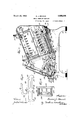
- Fig. 1 is a side elevation with parts shown in section.
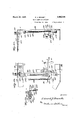
- Fig. 2 is a verticallongitudinal section on the line 2-2 of Fig. 3.
- Fig. 3 is a top plan with parts broken away.
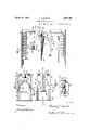
- Fig. 4 is a detail View illustrating the shifting mechanism for the keyboard and portions of the rocker arms and keyboard resetting mechanism.
- Fig. 5 isa detail sectional View, with parts .shown in elevation, of the coin supporting tray and ejecting mechanism.
- Fig. 6 is a rear view of the coin tray.
- Fig. 7 is a side elevation of one of the partitions forming a part of the coin.V tray.
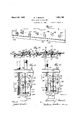
- Fig. 9 is a view similar to Fig. 5 looking from the opposite side of the'mlachine.
- Fig. 10 isa detail front elevation of the mechanism for placing the machine on a basis for ejectingcoins from a fraction of a dollar..
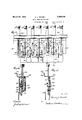
- Fig. 11 is a top plan of a unit to'be attached to the machine fon delivering a double numv ber of coins upon each operation of the keys.
- Fig. 12 is a side elevation of the unit shown in Fig. 11.
- Fig. 13 is a horizontal section on line 13-13 of Fig. 12.
- Figs. 14 and 15 are fragmental details showing the normal and downward position of the operating keys of the units shown in Fig. 11.
- Figs. 16' and 17 are detail sectional views on lines 16-16 and 17-17, respectively, of Figs.
- Fig. 1S is a fragmental detail view showing in plan the locking mechanism for the fraction yof a dollar keys.
- Fig. 19 is a bottom plan of the closure for the coin chute.
- Fig. 2O is a plan view with parts in section of the closure for the coin chute.
- Fig. 21 is a section on the line 21-21 of Fig. 20.
- Fig. 22 is a longitudinal section on the line 22-22 of Fig. 20.
- Fig. 23 vis -a side elevation, with parts in section, of the holding and releasing means for the shiftable keyboard.
- Fig. 24 is a section on the line 2424 of Fig. 23 looking in the direction of the arrows, anc
- Fig. 25 is a section on the line 25-25 of Fig. 23 looking inthe direction of the arrows.
- FIG. 1 indicates the supporting castings of rwhich there is one on each side of the machine, these supporting castings having the legs 2 at each end and the legs having the removable blocks 3 secured thereto.
- Supported onthe castings 1 are the side frames 4 and the bottom plates 5 and 6, the bottom plate 5, as shown, extending downwardly at an angle from the rear end oit' the machine towards the center and the bottom plate 6, as shown, extending downwardly at an angle from the ⁇ forward end of the machine towards the center, the inner ends oi the plates 5 vand 6 meeting as shown.
- rI ⁇ he side frames 4 are connected by the transversely extending rods 7 which extend therebetween.
- a set screw 8 passes through one of the side frames and engages in a threaded opening 9 formed in the end of the rod, the
- each of the rocker arms 13 is a depending arm 15 which is pivotally connected at 16- to a pusher bar 17 said pusher bar extending parallel with the base plate 5 and having at its forward end the extension 18 which is on a somewhat higher plane and has its forward end downwardly curved as shown at 19.
- a depending arm 15 which is pivotally connected at 16- to a pusher bar 17 said pusher bar extending parallel with the base plate 5 and having at its forward end the extension 18 which is on a somewhat higher plane and has its forward end downwardly curved as shown at 19.
- Securedto the base plate 5 is an inverted' U shaped bracket 20 which limits the downward movement ol the rocker arms, the horizontal portion ot this bracket being somewhat ree sil-lent so thatwhen the rocker arms are de# pressed it will take up ⁇ jar and thereby protect the operating mechanism as will be read- 'lhe upper edges of the vrocker arms are rounded as shown at 21 to form a bearing tor the lingers of the operating keys.
- the downwardlycurved ends-19 formed on the extensions 1.8 olf the pusher bars 1i' are pivotally connected at 22- to the slidable plates 23 which mounted upon the rollers 24 and 25 which are rotatably supported by the vertically extending plates 26 and 27 respectively.
- the rollers 24 and 25 operate in the elongated openings 28 and 29 termed in the plates 23, said slots allowing the plates to be slid parallel to the bottom plate 6.
- Secured on opposite sides of the plate ⁇ 27 are the fibre blocks v30 and 31 a metal plate 32 being secured to the outer face ot' the block 31 and iaving notches 33 l'ormed in the upper edge thereof.
- the plates 23 have the downwardly extending projections 34 and 35 'formed on the lower edge, the projection 34 i when the plate 23 is inits rearward position engaging the libre block 30 andthe projection 35, when the plate 1s in its forwardmostposr tion extending throughthe notches 33 in the Y plate 32 and engaging the fibre block 34.
- upwardly extending projection 36 is formed on the Jforvmrd upper edge of the pla-te 23 and forms a shoulder 37 lfor a purpose which will be presently brought out.
- a projection 38 is formed on the forward lower edge of the f plate 23 and normally rests upon the block 39 secured to the forward faceot the plate Pivotally connected at 40 to each of the sliding plates 23 is a coin ejecting linger 41 which passes through the plate 42 at the front of the machine and through a slot 43 formed in the lower edge of the coin 'tray a.
- a second linger 45 Pivotally connected at 44 to the lingers 41 is a second linger 45 which also passes through the opening in the plate 42 and the opening 43 Vin
- This lower linger 45 normally rests on and is slidable uponthe plate 46 secured to the inwardlyextending portion 47 of the upwardly extending flange 48 which is formed on the forward edge of the bottom plate 6.
- a bolt 49 passes through the fingers 41 and 45 and receives the nut 50 which engages the lower face olf thev linger .45.
- a coiled spring 51 surrounds the bolt 49 between the lingers and normally holds'them in i spaced relation so that thenger 45 will engage the plate 46 and the nger 41 -will be in position toveject the coins 52 which are supported in the coin tray a.
- the coin tray a comprises the back plate 53, the bottom 54 and the vertically extending partitions 55 which. provide a plurality or compartments oli' different sizes to receive stacks ol: coins oli various denominations.
- y Formed in the rear face of ⁇ the back plate are the longitudinally extending grooves or recesses 56 and 57,the groove or recess 56 being adjacent the upper edge and the groove or recess 57 being adjacent the lower edge.
- the vertically extending partitions 55 are formed on ⁇ their rear edges with the vertically spaced lugs or projections 58 and 59 which pass through openings formed in the bacl' 53 and into the grooves or recesses 56 and 57.
- the lugs or projections 58 and 59 have openings ⁇ therein to receive the rods 60 and 6l which extend longitudinally of the grooves or recesses 56 and 57 and secure the partitions 55 to the back plate
- the coin engaging members 65 have the openings 66 formed therein to receive the rod 64, said rod limiting the swinging movement of the ⁇ members in either direction.
- the rear ends of the coin engaging members are rounded as shown at 67 to engage locking levers to be later described. Plates 68 are seengage over the portion 69 of the machine to hold the tray in position. As shown eight stacks of coins will be supported by the tray. Reading from the lelthand side of the tray the lirst three stacks will be pennies, the fourth stack nickles, the lilith and sixth stacks dimes, the seventh stack twenty-live cent pieces, and the eighth stack fifty cent pieces. The plungers operating in the second and third stacks of pennies will deliver two at a time. Y
- Pivot-ally mounted onthe transversely e2;- tending rod 70 are the locking levers 71 there being one locking lever for each ofthe slide able plates 23.
- Each of the locking levers comprises Va substantially vertically extend# ing portion 72 and a substantially horizontal portion 73, the portion 73 having a roller 7 4 mounted at its rear end.
- tending portion of the locking lever extends in position to be engaged by the rounded portion 67 of the coin engaging member G5 and Y when there are coins in the-particularr compartment of the coin tray ,thecom engaging The vertically er;-V
- the lower end of this bar 80 is bent at right angles as shown at 82 tof/erm a portion adapted to be engaged by the fingers of the operator of the machine to slide the bar vertically.
- the upper end of the bar is provided with the right angle extension 83 which extends beneath the rocker rod 75 and in engagement therewith.
- Formed on or secured to the bar 80, intermediate-the ends, are the headed studs or projections 8a and 85, the stud or projection 84 operating in the opening 77 and the stud or projection 85 operating in the opening 7 8 of the braciret. frs moreI particularly illustrated in Fig.
- the headed studs or projections 8i and 85 normally engage the lover edges of the openings 77 and 78 and when the locking levers 71 are in position with the roller 7el engaging the shoulders 37 of the slidable plates 28 the substantially horizontal portions of the locking levers will engage on the rocher rod 75. 'Vhen it is dee sired to raise the locking levers so as to release the slidable plates 23 the operator engages the extension 82 on the lower end of the bar 80 and pushes the same upwardly so that the stud or projection 8d will be received in the right angle extension 79 of the opening 77. When the lug or projection 84 is in the right angle extension 79 of the opening 77 the bar 80 will be held in its raised or uppermost position.
- a frame Secured to the underside of the machine and extending forwardly to a point beneath the central opening 88 of the chute 86 is a frame having an end portion 89 and side arms 90 said side arms being provided 1n their inner faces with the longitudinally extending grooves 91 in which operate a slidable plate 92 which normally extends beneath the central opening 88 of the chute and forms a closure therefore.
- a substantially semi-circular depending flange 98 whichforms a finger engaging portion for engagement by the operator for sliding the plate longitudinally of the frame to remove the plate from beneath the opening 88 and allow the coins to pass therethrough into the hand of the operator or in a suitable receptacle provided for the reception of the coins.
- the plate 92 is formed on its rear end with the arms 94 which have their ends bent upwardly at right angles to form the projections 95 these projections adapted, when the plate is slid rearwardly of the frame to engage the bumpers 96 which may be of rubber or other suitable resilient material, they being connected to the end 89 of the frame.
- a coiled spring 98 Carried in this cylinder or tube 97 is a coiled spring 98 one end of which engages the end 89 of the frame and the opposite end engages an upwardly extending projection 99 formed on or secured to the upper face of the plate and operable in a longitudinally extending slot 100 which is formed in the bottom of the cylinder or tube.
- the coiled spring 98 normally holds the plate in its forwardmost position but when the plate is slid rearwardly by theoperator the spring will be compressed and automatically return the plate 'to its forwardmost position when released by the operator to close'the opening 88 in the chute 86.
- An opening 101 is formed in one ofthe side arms90 ⁇ of thev frame and pivotally connected to the upper surface of the plate 92, adjacent one longitudinal edge thereof, a latch 102 said latch having on its rear end a right angle projection 103 and on its forward end aprojection 104 which carries a downwardly extending pin or lug 105. Zhen it is desiredfto yhold the plate in its rearward position to allow the coins to freely pass through thel opening 88 the latch 102 is swung so that the extension 103 thereof will engage in the opening 101 and thereby hold the plate against automatic return by the coiled spring.
- each side arm 90 of the frame adjacent the forward end thereof, is an opening 107 for securingcertain attachments to the chute, one of these attachments being indicated in dotted lines 108 and being in the form of an auxiliary chute which is more particularly adapted for ydischarging 35 the coins directlyinto an envelope.
- suoli an auxiliary chute will be of particular advantage in making up pay rolls where the pay is delivered to the employee in an envelope.
- auxiliary chute When this auxiliary chute is used the end thereof ⁇ may be positioned into the mouth of the envelope and, the coins which are delivered from the machine will pass directly into the envelope.
- auxiliary chute will be provided on opposite sides with spring controlled plungers 110 which will enter the openings 107 formed in the side arms 90 of the frame for supporttl e auxiliary chute. While I have de- ⁇ scribed the attachment in the form of an auxiliary chute for delivering coins directly into pay envelopes or the like it will be understood that the openings in the sides of the frame might be equally as well adapted for holding ⁇ various forms of attachments for delivering the coins from the main coin discharging chute into different positions or different forms of receptacles.
- the coin ejecting mechanism l For operating the coin ejecting mechanism l provide a plurality of keys which when depressed operate the coin ejecting mechanism to eject different combinations of coins, the keys being carried by a slidable keyboard which sets at an. angle so that the designating marks upon the keys may be eas- R ily read by the operator.
- the keyboard is mounted upon rollers so as to be freely mov'lable into its different positions without undue friction. As has been previouslystated when the keyboard is in its raisedposition the machine will operate on a changer basis and when the keyboard is in its lowered position the machine will operate on a payer basis. y y
- the vkeyboard comprises the top plate 111 and the bottom plate 112 spaced therefrom the top plate being supported for sliding movement upon the rollers 113 which are secured to each of the side frameset of the machine.
- the front supporting rollers will be on a somewhat lower plane than the rear supporting rollers so as to support the keyboard in slightly inclined position so that, as has been previously stated, the designating marks upon the several keys formingy a part of the keyboard may be easily read by the operator.
- a block 116 Secured to one of the side frames 4 is a block 116 which is adapted to be engaged byv the arms 117' which are secured to ythe keyboard, these arms vengaging' the block to ⁇ limit both the upward and downward movement of the keyboard.
- the edge of the upper plate 111 will be cut away as shown at 118 so as to leavespace to prevent the block 116 from engaging with the plate.
- the upper plate 111 is also cutaway, adjacent one edge, as shown at 119 to form a sight opening through which will show either Chg, when the keyboard is in raised position, or the word Pay, when the keyboard is in lowered position, so as to indicate to the operator whether the machine is set for operation on-the fchanger or payerv basis.
- Both the upper plate 111A and the lower Yplate 112 are providedwitha plurality of-open-l ings, those in the'lower plate being in alignment with those in the upper plateatoreceive the substantially vertically extending, key bars 120, said key bars having on their upper ends the buttons ory finger pieces 121 bearing designating marks preferably in the form of numerals.
- Eachof the key bars is provided on its 'edges' with a Vcut-'out or notched portion 1122 and a ⁇ coiled spring 123' surrounds'each of the bars, ⁇ the upper end of the spring engaging the shoulder formed by the cut-out or notched portions 122 and the lower end engaging the upper face of the bottom plate 112 so as to normally hold the key bars in their raised positions.
- Each of the key bars is formed on its lower end with a horizontal extension 124 which in turn has a plurality of downwardly extending fur gers or projections 125 which will be spaced in such a manner as to engage the desired rocker arms to eject the proper combination of coins from the coin tray.
- the lingers or projections 125 are of such a width that they may be received between the rocker arms for a purpose which will presently be apparent.
- the lingers or projections 125 when the keyboard is in raised position, or on a changer basis engage a certain group of the rocker arms and when in a lowered position or on the payer basis other projections or iingers will engage other groups of rocker arms those projections or lingers not engaging the rocker arms being received in the space between the rocker arms and being thereby inoperative.
- the upper edges of the rocker arms being rounded will allow the ends of the fingers or projections 124 to properly operate to depress the rocker arms and thereby operate the pusher bars andassociated coin ejecting mechanism the angle at which the coin bars are arranged relative to the slidable plates 23 and associated coin ejecting mechanism being such as to allow the parts to freely slide and the' coin ejecting lingers to properly engage the coins which are supported at an angle in the coin tray to prevent accidental displacement of the coins in the several stacks.
- the unit comprises a plate 126 which on one edge is formed with the vertically extending flange 127 the upper edge of which is bent at right angles to form the horizontal portion 128 which is provided with the longitudinally spaced openings 129 whereby the unit may be secured to the plate 111.
- the transversely extending bars 114 extend over the upper face of the plate 126, the plate being formed with one longitudinal edge at an angle to allow the propel' positioning of the keys.
- a plurality of substantially vertically extending key bars 130 are carried by the plate 126 and extend through the openings formed therein, certain of the key bars er.- tending on one side of the vertically extending plate 131 depending from the plate 126 and other key bars extending on the opposite face thereof.
- Each of the key bars 130 operated by the keys 15o, 151, 15e, 154, and 155 is formed on one vertical edge with a rack 132 which meshes with a gear wheel 133 rotatably connected to the depending plate 131 by means of the screw or rivet 134.
- a rack 132 which meshes with a gear wheel 133 rotatably connected to the depending plate 131 by means of the screw or rivet 134.
- gear Wheels on each face of the plate being longitudinally spaced as more clearly illus trated iny Fig. 12 of the drawings. lVhile any number of gear wheels may be used as required
- the ⁇ unit which is disclosed in the drawings comprises five of such wheels three being mounted on one face of the depending plate and two being mounted on the opposite face thereof. A description of one of the gear wheels and its associated parts will sufice for all.
- Each of the gear wheels has the studs or pins 135 and 136 secured to one face thereof, these studs or pins being so arranged as to extend on diiferent sides of the vertical center of the gear securing pins or rivets 134 as more clearly illustrated in Fig. 12 of the drawings.
- a coiled spring 137 has one end secured to the plate 126 and the opposite end connected to the key bar 130 so as t-o normally hold the key bar in raised position.
- a plate 138 is carried by each of the screws or rivets 134 being positioned between the associated gear wheel and the face of the plate 131 these plates being provided with an elongated vertically extending opening 139 whereby the plate may be moved vertically.
- Each of the plates 138 is also provided with a foot or extension 140 which is adapted to engage the rocker arms for operating theucoin ejecting mechanism.
- a coiled spring 141 has one end secured to the plate 126 and the opposite end connected to the plate 130 so as to normally hold the plate in raised position.
- Pivotally connected to the plate 138, at 142 and 143 respectively are the vertically extending dogs or arms 144 and 145 the upper ends oit these dogs or arms being respectively in a position to be engaged by the pins or studs 135 and 136 when the gears 133 are operated, the upper ends of the arms or dogs being drawn inwardly towards one another by means of the coiled spring 146 which has its ends secured to the dogs.
- the inward movement of the Vdog 144 is limited by the pin 147 and the inward movement of the arm or dog 145 is limited by the pin 148, these pins 147 and 148 being formed on or secured to the depending plate 131.
- Secured to the upper ends ot l the key bars are the finger pieces or buttons which bear designating marks showing the coins which will be ejected from the coin tray upon each operation of the key bar.
- the buttons or linger pieces are shown at 149, 150, 151, 152, 153, 154 and 155.
- the stud or pin 135 will be positioned above the upper end of the arm or dog 144 and the stud or pin 136 will be positioned in engagement with the inner vertical edge oi ⁇ the arm er dog 145 intermediate the ends thereof.
- the rack 132 meshing with the gear 133 will rotate the gear in the direction indicated by the arrows in Figs. 12 and 14 of the drawings so that the stud or pin 135 will engage the upper end of the arm or dog 144 and thereby lower the plate 138 so that the arm or extension 140 will engage Athe desired rocker arms 13 to eject the coins from the tray.
- This movement of the gear wheel 133 raises the stud or pin 136 to a position above the upper end ofthe dog or arm 145.
- the key bar starts to return to its normally raised position it naturally rotates the gear 133 in the opposite direction or in the direction indicated by the arrow in Fig. v15 of the drawings and allows the plate 138 to be raised by the coiled spring 141 until the stud or pin 136 engages the upper end of the arm or dog 145.
- the continued movement of the gear wheel forces the arm or dog downwardly and carries with it again the plate 138 which ejects the same numberV of coins as has been ejected upon the downward movement of the key bar.
- the stud or pin 136 When the key bar reaches substantially its uppermost position the stud or pin 136 will move from the end of the arm or dog ⁇ 145 and allow the plate 138 to again be raised to its original position by the coiled spring- 141.
- the coiled spring ⁇ 141 acts to raise the key bar to its original position after the button or finger piece associated therewith has been released by the operator. It will be' understood that while the operation of each of the key bars ej ects a difference combination'of coins from the coin tray nevertheless the movement of the several associated parts will be the same and it might be further stated that the same combination of coins will be ejected from the coin tray by the keys of the just described unit where the machine is operating on a chance or on a pay basis.
- the plates 138 are of such a length as to extend ever number of the rocker arms and will operate to discharge the same number of coins whether the machine is on a changer or payer basis.
- lever wl ich is operable beneath the bottom plate 5 in reach of the operator of the machine.
- the lever is indicated at 156 and at its inner end is connected to a pin 157 which passes through the bottom plate 5.
- a downwardly' extending knob 158 is formed on or secured to the outer end of the lever for engagement by the operator.
- a lever 159 Secured to the upper end of the pin 157, above the bottom plate 5, is a lever 159 which is ofV less length than the lever 158 as is more particularly illustrated in Fig. 4 of the drawings.
- EX- tending upwardly from the free end of the lever 159 is a stud or projection 160 to which is connected one end of a coiled spring 161 the opposite end of the spring being secured in an eye 162 formed adjacent the lower end of a substantially vertically extending rod 168, the Lipper end of said rod 168 being secured to the upper plate 111 of the keyboard by means of a screw 164 or other suitable fastening means.
- Formed in the bottom plate 5 is an arcuate shaped opening 165 through which extends a pin 166 which is secured to the levers 156 and 159. The movement of the levers is limited by the engagement of the pin 166 with the ends of the opening 165.
- the lever 156' adjacent the free or outer end, operates in a guide which is secured to the underside of the bottom plate 5 by means of the screws 167 or other suitable fastening means.
- This guide comprises the bottom plate 168 and the top plate 169 which receive therebetween, at the ends, the spacing strips or blocks 170 which space the top and bottom plates apart a sufficient distance to allow the lever 156 to freely op As shown more particularly in dotted lines in Fig.
- the top and bottom plates of the guide are arcuate in shape and the'top plate 169 is provided with a plurality of longitudinally spaced openings 171 adapted to receive a projection 17 2 formed on the upper face of the lever 156, said projection 172, when received in one of the openings 171, holding the lever in its adjusted position.
- an angle bracket 17 8 Secured to the upper surface of the bottom plate 5, adjacent the rear edge thereof, is an angle bracket 17 8 carrying the adjusting' srrew 174 which extends through the vertical portion thereof, said adjusting screw passing freely through the bracket and being adjusted by means of the thumb nut 175 which is carried thereby and engages one face of the bracket.
- the adjusting screw is formed on one end with a perforation 176 in which is connected one end of a coiled spring 17 7, the opposite end of the coiled spring being connected in an eye 178 formed in the rod 163 above the eye 162.
- the lever 156 is swung rearwardly of the machine it will carry with it the relatively short lever 159 and the coiled spring 161 will draw the keyboard towards the rear of the machine.
- the lever 156 being of a spring construction will position the proj ection 172 in one of the openings 171 and the lever willl be held in its adjusted position.
- the keyboard is on av changer basis and when it is desired to change to a payer7 basis the lever 156 is swung inwardly and carries with it the lever 159.
- This movement of the levers allows the coiled spring 161 tov draw or push the keyboard downwardly, the downward movement of the keyboard being aided by gravity as the keyboard is mounted, as has been previously stated, at an angle.
- the coiled spring 177 When the keyboard is in its lowered position or on the payer basis the coiled spring 177 will be expanded or placed under tension and this spring will aid in returningr the keyboard to its uppermost position when the lever 156 is moved for that purpose.
- the spring 17 7 acts more or less as a balance spring and for automatically returning the keyboard to raised position when said board is moved into lowered position for one operation only in a manner as will be later described.
- a vertically spaced screw or bolts 179 upon which are mounted a vertically eiitending plate 180, said plate having the elongated openings 181 through which the screws pass.
- a lug or projection 183 being formed at the lower end thereof.
- Secured to this lug or projection 183 is one end of a coiled spring 184, the opposite end of the coiled spring being secured to an eye 185 which is formed on or secured to the side frame 4.
- This coiled spring 184 normally holds the plate 180 in its rais-ed position.
- the right angled projection 185e which carries the roller 186, said roller projecting from that face of the lug or projection adjacent the side frame 4- for a purpose which will be presently described.
- the vertically extending projection 187 Formed on the upper end of the plate 180 is the vertically extending projection 187, this projection lbeing preferably positioned adjacent the vertical ycenter line of the plate.
- a 'flat spring 189 Securedto the underside of the top plate 111 of the-keyboard, by means of the rivets or other suitable fastenings 188 is a 'flat spring 189 the free end of which willV normall'jsT be spaced. from the bottom of the plate.
- a block 191 Extending upwardly from the spring, and through the plateY 111, is the knob or linger piece 190 and secured to the underside of the spring is a block 191 having the recess 192 formed inits under face.
- a roller 193,'said roller Mounted in the recess 192 is a roller 193,'said roller being of such a diameter as to leave a space on each side thereof of a suflicient width to receive the projection 187 formed onthe upper end of the plate 180.
- latchA 195 Pivotally connected at'194 to the side frame l and between the inner face ofsaid side plate and the slidable plate 180 is latchA 195, one end of which is beveled'assliown at 196 and the opposite end is reducedl as shown at 197 and extends over the top of the roller 186 and normally in contact therewith. 55e-,
- cured to the extension 197 is one end of a coiled spring 198 the opposite end of the spring being secured to a projection 199V formed on the frame.
- ThisY spring 198 has a tendency to normally hold the extension 197 in substantially horizontal position the upward movement thereof being limited by a pin 200 extending inwardly from the side frame 4.
- YExtending upwardly from ⁇ the bottom plate 5 are the brackets orstandards 201 and 202 the bracket or standard 201y having the inwardly extending horizontal pin 203 and the bracket or standards 202 having the inwardly extending horizontal pin 204e.
- a coiled spring 206 Qarried by the pins 203 and 2041for vertical swinging Vmovement is'theiframe 205, a coiled spring 206 being positioned on thepin 203 and engaging the inner ⁇ face ofr one. arm of the frame 205 as is more clearly shown in Fig. 4f of the drawings.v
- the opposite end of the coiled spring is engaged by a washer 207 which is held upon the pin by means of the nut 208.
- the coiled spring 206 not only allows for a slight longitudinal movement of the frame between the pins but also nomnally holds the frame 205 in raised or substantiallv horizontal position.
- the bar 209 Secured to the frame 205 and extending beyond one endthereof is the bar 209 to the outer end of which is .se--
- a plate 210 to which the bell crank lever 211 is pivotally connected at 212.
- a coiled spring 213 Secured to the vertical arm of the bell crank lever 211 is one end ofv a coiled spring 213 the opposite end ofthe spring being connected at 214 to the plate 210.
- This coiled spring 213 normally holds the hcwfmntel arm of the bell crank lever 211I in engagement with the iin-ner surface of the latch 195.
- rlille frame 205 and the extensionbar 209 are positioned beneath the rocker arms as more clearly illustrated'in Fig of the drawings so that when the rocker arms are depressed they in. turn will depress the frame and-its associated parts.
- the leverv 156 When the machine is on Vthe payer basis and is temporarily set to changer, the leverv 156 will be in its forward position, the spring 161 will be slack, and the spring 177 will not be so strong as to prevent the keyboard from falling back to its payer position. When, however, the machine is permanently set as a changer, the lever 156 will be in its rearward position, tensioning the spring 161. Then if the keyboard be shifted temporarily to its lower or payer position, the combined tension of the spring 177 plus the spring 161 will be suicient to raise it, against the force of gravity, back to its changer position. f
- the lower end of the extension 217 of the vkey ⁇ 215 is provided with the horizontal portion 219 which extends over and is adapted to make inoperative those coin ejecting iingers which operate-to eject both'a 50g*J piece and a 2595 piece, so vthat when the key 215 is depressed the vchange will be made onl from 25e ⁇ or 7 5e as desired.
- the key 215 is norma'lly held in its raised position by means of a coiled rspring 220 andthe key 216 is normally held in raised position by the coiled spring 221.
- each of the extensions 217 and 218 of the keys Formed adjacent the lowerend of each of the extensions 217 and 218 of the keys are the vertically spaced openings 222 and 223, these openings being adapted to receive theprojections 224 formed on the frame 225 ⁇ whichis pivotally connected to the bra-ckets or standards 226 which are secured to the bottom plate 6.
- This frame 225 is normally held in raised position by the coiled springs 227 with the projections 224 received in the lower openings 223 of the key extensions.
- the keys When one of the keys is depressed it will engage the'beveledY upper surface of the proj ection 224 and allow the .projection to be received Vin the upper opening 222.
- the coin ejector fingers When in this position the coin ejector fingers will be thrown into inoperative position as has been previously described.
- the inwardly extending portions 228 Y are Formed on the frame 225 are the inwardly extending portions 228 Y the lower surfaces of which are rounded as CIJ A. shown at 229 to be'engaged by the swinging frame 230.V
- the sliding plates 23 on their forward movement will engage the swinging frame 230 and throw the projection 224 out of the openings 222 in the downwardly extending portions 217 and 218 of the keys 215 and 216 thereby allowing the keys to be raised by their respective coiled springs.
- the changer is to be operated to ⁇ eject change from 25e, 50c or 7 5c it will only act on this basis for a single operation and the keys are returned to their normally raised position after such single operation.
- the machine is set to operate on a changer basis and change is to be made after deducting 259': from a dollar the 25 key will be depressed and will operate the rocker arms to deliver a 50eL piece and a 25u/S piece from the coin tray. Tf the machine is operating on a payer basis when the key bearing the designating mark 25e is depressed on that rocker arm will be operated to eject a 25e piece from the coin tray.
- I might describe the operation or' the key bearing the Vdesignation 39 on both a changer or payer basis. With the keyboard mounted on a changer basis and a purchase amounting to 39e is made then the 39g?v key will be depressed to give 61e in change.
- De pression of the 39e key will eject a penny from the first stack of coins, a dime from the fourth stack of coins, and a 509i piece from the eighth stack of coins.
- the keyboard shifted to operate on a payer basis it will be desired to eject 39e when the ⁇ 39e key is de pressed.
- two pennies With the depressing oi the key, when on a payer basis, two pennies will be ejected from each of the second and third stacks of coins, a dime from the sixth stack of coins,A and a 25e piece from the seventh stack of coins.
- a money handling machine comprising a coin tray, means ⁇ for ejectingthe coins from the tray, and a bodily sliiftable keyboard for operating the coin ejectingmeans.
- a money handling machine comprising a coin tray, means for ej ecting the coins from the tray, and a shiftable keyboard for operating the coin ejecting means, said keyboard when in one position operating the coin ejecting means for ejecting certain combinationsl of coins from the tray and'When shifted into another'position ejecting another combination ofcoins from vthe tray.
- a money handling machine comprising a coin tray, means including aplurality o' ejectors for ejecting the coins from the tray; a shiftable keyboard for operating the ejectors, means for operating a predetermined combination of ejectors When the keyboard is in one position and means for operating another predetermined combination of ejectors When the keyboard is in another position.
- a money handling machine comprising a coin tray, means including a plurality of ejectors for ejecting the, coins from the tray, and a shiftable keyboard carrying a plurality of keys Which When depressed operate the coin ej ectors, each key being provided With a designating mark, the key VWhen depressed While the keyboard is in one position delivering coins from the tray in such an amount equal to the difference of the designating mark on the key and one ⁇ dollar and when depressed While the keyboard is in another shifted position delivering coins from the tray equal to the amount of the designa-ting ⁇ mark on the key.
- Amoiiey handling machine comprising a 'coin tray, means including a plurality ofejectors for ejecting the coins from the tray, rocker arms for operating the ej ectors, a shiftable keyboard carrying a plurality oic keys adapted to be depressed, and a plurality of proj ect-ions formed on each key, certain of said projections on the key-s engaging certain oi the rocker arms when the keyboard is, in oney spaced rocker arms for operating the ejectors, a shiftable keyboard carrying a plurality of keys adapted to be depress-ed, and a plurality of projections formed on each key, certain of the projections on the keys engaging certain of the rocker arms When the keY board is in one position and others of the projections engaging other of the rocker arms When the keyboard is in shifted position.. those projectionsnot engaging the rocler arms being receivedin Jthe spaces between said rocker arms when the keys are depressed to operate the rocker arms to eject
- a money handling machine comprising a (Joint-ray, means for ejecting the coins ktrom the tray, a bodily shitable keyboard for operating the coin ejecting means, and means for shifting Vthe keyboard.
- A. money handling machine comprising a coin tray, means 'for ejecting the coins from the tray, a shittable keyboard for operating f i the coin ejecting means, and a lever for shifting the keyboard.
- a money handling machine comprising a .coin supporting tray, means for ejecting the ooinsfrom the tray, a bodily shiftable keyboard for operating. the coin ejecting means, and means for holding the keyboard in its shifted positions.
- a money handling machine comprising a coin support-ing tray7 means for ejecting the coins from the tray, a bodily shiftable keyboard for operating the coin ejecting means, and means for shifting the keyboard and holding the same in its shifted positions.
- a money handlingmachine comprising a coin supporting tray, means for ejecting the coins from the tray, a shiftable keyboard for operating the coin ejecting means, means for holding the keyboard in one of its shifted positions, means for moving the keyboard to its other position, and means Jfor automaticalerating the coin ejectinglmeans, means for lasV
Landscapes
- Physics & Mathematics (AREA)
- General Physics & Mathematics (AREA)
- Control Of Vending Devices And Auxiliary Devices For Vending Devices (AREA)
Description
March 22, 1932. E. J. BRANDT HONEY HANDLING IACHINE 9 Sheets-Sheet 2 Filed May 24, 1924 March 22, 1932. E. J, BRANDT l MONEY HANDLING IIAGHINE Filed May 24, 1924 9 Sheets-sheet 3 March 22, 1932. E, 1 BRANDT MONEY HANDLING MACHINE Filed May 24, 1924 9 Sheets-Sheet 4 March 22, 1932. E. J. BRANDT 1,850,198
MONEY HANDLING MACHINE Fileduay 24, 192A 9 sheets-sheet 5 EEE March 22, ,1, BRANDT 1,850,198`
MQNEY HANDLING MACHlNE Filed May 24v,` 1 924 9 Sheets-Smet, 6
MalCh 1932. E J, BRANDT 1,850,198`
MONEY HANDLING MACHINE Filed May 24. 1924 9 Sheets-Sheet E. J. BRANDT MONEY HANDLING- MACHINE March 22, 1932.
9 Sheets-Sheet 8 Filed May 24, 1924 Mmh 22, 1932.
E. J. BRANDT MONEY HANDLING MACHINE 9 Sheets-Sheet Filed May 24, 1924 Patented Mar. 22, 1932 Unire f Esi-ares PATENT oFFlcE i EDWARD J. BRANDT, 0F WATEBITOWN, y VISCONS'INQ `ASSIGNR TO BRANDT AUTOMATIC CASHIER COMPANY, GF WATERTOWN, WISCONSIN, A CORPORATION 0F IISCONSIN` MONEY HANDLING MACHINE Application led May 24,
5j, present invention has for its principal object the provision ot a machine which may be readily changed from a payer basis to a changer basis or from a changer basis to a payer basis, a movable keyboard being provided i'or this purpose, said keyboard having a plurality of keys bearingV designating marks, the keys when depressedv engaging suitable mechanism for delivering coins of diii'erent denominations from a coin tray or 5 magazine. When on a payer basis when a Y mark upon the particular key `depressed and when on a changer basis coins will be ejected from the coin tray of an amount of the diderence between that of the designating mark on the key and one dollar, the `machine normally operating on what may be termed i a dollar basis although I provide means whereby the machine may be ,operated on a basis ot fractions of a dollar. In other words say that when the machine is operating on a dollar basis and it is `desired to deliver change kfrom the coin tray/after deducting l'f; from the dollar the key bearing the designating mark seventeen will be depressed and through suitable mechanism 83e will be delivered from the coin tray. If operatingon a pa-yer.
F5 basis and the key bearing the designating mark seventeen is depressed coins amounting to 17e will be ejected romthecoin tray. If the-machine is to be operated on abbasis of a fraction of a dollar I have provided suitable mechanism which whenoperated will deliver change froma fraction of a dollar. For example say that it is desired to deliver change from 50e after deducting 1795k then the mechanism to place the machineV on a fraction of a dollar basis will be operated to" deliver change from 50e. When the key bearing the designating mark seventeen is depressedthen 33e change will be delivered from the coin tray. l y t y y A further object of the invention resides 1924. serial No. 715,662.V
in the provision of means whereby the machine may be set to operate either'on a payer7 or changer lbasis but which may be moved to perform one transaction on the opposite basis. In other Awords say that the /machine is normally setV to operate on a payer basis I have provided means whereby the keyboard may be moved so that one transaction may be performed on the changer. basis and I have also provided means whereby when such single transaction is performed the keyboard will be automatically returned to that position or basis'upon which it is set to normally operate.
A ,further object of the invention resides in the provision of means whereby when the keyboard s set to operate on a payer basis the mechanism for Athrowing themachine on the basis of a fraction of a dollar will be held in inoperative position.
Still another object of the invention consists in providing a plurality of what may be termed double actin@f keys and ejecting mechanism so that coins will be ejected both when the keys are depressed and when returning to their normal position. In other wordsI have provided mechanism whereby when a key is depressed it will deliver the `amount designated upon the key ,and will also deliver a like amount upon the upward movement of the key or the movement of the key in returning to its oriffinal or normal' position. For an example I will say that a key bears a designating mark to deliver five pennies from the coin tray or magazine. When this key is depressed it will deliver tiver pennies from the coin tray and when it raises or returns to its normal position an additional live pennies will be delivered from the tray. It will thus be seen that I have provided a very quick movement whereby a plurality of coins of a similar denomination may be delivered from the coin tray.
A still'further object of the invention'resides in the provision ofa cointray or magazine of novel construction,` saidV coin tray or magazine having a plurality of compartments formed by vertically extending partitions, saidpartitionsbeing detachably connected to aback plate, Ithe tray being removably supported upon the machine so that when desired it may be removed, with the coins therein, and deposited in a safe or other receptacle over night.
As another object I provide a novel form of discharge chute for the coins delivered from the tray or magazine, said chute being provided with a slidable bottom or gate which is normallyheld in closed position but which may beflocked in open position, means also being provided whereby a spout may be connected to the chute for delivering the discharged coins directly into pay envelopes or other suitable receptacles.
As a further object of the invention I construct the bottom of the machine and the `operating mechanism at such angles that the keys of the keyboard may be readily seen and the lejecting mechanism is operable without friction and so positioned as to readily ejectthe coins from the coin tray or magazine, said coin tray or magazine being supported at an inclined position upon the machine so that the coins will be supported at an angle and against accidentaldisplacement from the machine.
With the above and other objects in view,
which will appear as the description pro-` ceeds, my invention consists in the novel details of construction, and arrangement of parts, described in the following specification and illustrated in the accompanying drawings, and while I have illustratedV and described the preferred embodiments of the invention, as they now appear to me, it will Vbe understood that such changes may be made as will fall within the scope of the appended claims. Y
IIn the drawings:
Fig. 1 is a side elevation with parts shown in section.
Fig. 2 is a verticallongitudinal section on the line 2-2 of Fig. 3.
Fig. 3 is a top plan with parts broken away.
Fig. 4 is a detail View illustrating the shifting mechanism for the keyboard and portions of the rocker arms and keyboard resetting mechanism.
Fig. 5 isa detail sectional View, with parts .shown in elevation, of the coin supporting tray and ejecting mechanism.
Fig. 6 is a rear view of the coin tray.
Fig. 7 isa side elevation of one of the partitions forming a part of the coin.V tray.
8 isa side'elevation of one of the slidable coin ejecting plates.
Fig. 9 is a view similar to Fig. 5 looking from the opposite side of the'mlachine.
Fig. 10 isa detail front elevation of the mechanism for placing the machine on a basis for ejectingcoins from a fraction of a dollar..
Fig. 11 is a top plan of a unit to'be attached to the machine fon delivering a double numv ber of coins upon each operation of the keys.
Fig. 12 is a side elevation of the unit shown in Fig. 11.
Fig. 13 is a horizontal section on line 13-13 of Fig. 12.
Figs. 14 and 15 are fragmental details showing the normal and downward position of the operating keys of the units shown in Fig. 11.
Figs. 16' and 17 are detail sectional views on lines 16-16 and 17-17, respectively, of Figs.
12 and 13.
Fig. 1S is a fragmental detail view showing in plan the locking mechanism for the fraction yof a dollar keys.
Fig. 19 is a bottom plan of the closure for the coin chute.
Fig. 2O is a plan view with parts in section of the closure for the coin chute.
Fig. 21 is a section on the line 21-21 of Fig. 20.
Fig. 22 is a longitudinal section on the line 22-22 of Fig. 20.
Fig. 23 vis -a side elevation, with parts in section, of the holding and releasing means for the shiftable keyboard.
Fig. 24 is a section on the line 2424 of Fig. 23 looking in the direction of the arrows, anc
Fig. 25 is a section on the line 25-25 of Fig. 23 looking inthe direction of the arrows.
In the drawings 1 indicates the supporting castings of rwhich there is one on each side of the machine, these supporting castings having the legs 2 at each end and the legs having the removable blocks 3 secured thereto. Supported onthe castings 1 are the side frames 4 and the bottom plates 5 and 6, the bottom plate 5, as shown, extending downwardly at an angle from the rear end oit' the machine towards the center and the bottom plate 6, as shown, extending downwardly at an angle from the `forward end of the machine towards the center, the inner ends oi the plates 5 vand 6 meeting as shown. rI`he side frames 4 are connected by the transversely extending rods 7 which extend therebetween. A set screw 8 passes through one of the side frames and engages in a threaded opening 9 formed in the end of the rod, the
opposite end of `the rod being eXteriorly 'f threaded as shown at 10 to receive an interiorly threaded sleeve 11. A set screw 12 passes through the opposite side frame and engages the interiorly threaded sleeve 11 as shown. It will thus'be seen that an adjustment of the rods may be secured for positioning the side frames or adjusting,` them one relative to the other. Pivotally connected to the side frames 4 are a pluraiity of rocker arms 13 which are nested as shown, said rocker arms being supported'in normally raised position by means ofthe coiled springs 14. the upper ends of the coiled springs being connected to the side frames and their lower ends being connected to the rocker arms. Secured ily app arent.
the coin tray.
to each of the rocker arms 13 is a depending arm 15 which is pivotally connected at 16- to a pusher bar 17 said pusher bar extending parallel with the base plate 5 and having at its forward end the extension 18 which is on a somewhat higher plane and has its forward end downwardly curved as shown at 19. Securedto the base plate 5 is an inverted' U shaped bracket 20 which limits the downward movement ol the rocker arms, the horizontal portion ot this bracket being somewhat ree sil-lent so thatwhen the rocker arms are de# pressed it will take up `jar and thereby protect the operating mechanism as will be read- 'lhe upper edges of the vrocker arms are rounded as shown at 21 to form a bearing tor the lingers of the operating keys.
The downwardlycurved ends-19 formed on the extensions 1.8 olf the pusher bars 1i' are pivotally connected at 22- to the slidable plates 23 which mounted upon the rollers 24 and 25 which are rotatably supported by the vertically extending plates 26 and 27 respectively. The rollers 24 and 25 operate in the elongated openings 28 and 29 termed in the plates 23, said slots allowing the plates to be slid parallel to the bottom plate 6. Secured on opposite sides of the plate`27 are the fibre blocks v30 and 31 a metal plate 32 being secured to the outer face ot' the block 31 and iaving notches 33 l'ormed in the upper edge thereof. The plates 23 have the downwardly extending projections 34 and 35 'formed on the lower edge, the projection 34 i when the plate 23 is inits rearward position engaging the libre block 30 andthe projection 35, when the plate 1s in its forwardmostposr tion extending throughthe notches 33 in the Y plate 32 and engaging the fibre block 34. An
upwardly extending projection 36 is formed on the Jforvmrd upper edge of the pla-te 23 and forms a shoulder 37 lfor a purpose which will be presently brought out. A projection 38 is formed on the forward lower edge of the f plate 23 and normally rests upon the block 39 secured to the forward faceot the plate Pivotally connected at 40 to each of the sliding plates 23 is a coin ejecting linger 41 which passes through the plate 42 at the front of the machine and through a slot 43 formed in the lower edge of the coin 'tray a. Pivotally connected at 44 to the lingers 41 is a second linger 45 which also passes through the opening in the plate 42 and the opening 43 Vin This lower linger 45 normally rests on and is slidable uponthe plate 46 secured to the inwardlyextending portion 47 of the upwardly extending flange 48 which is formed on the forward edge of the bottom plate 6. A bolt 49 passes through the fingers 41 and 45 and receives the nut 50 which engages the lower face olf thev linger .45. A coiled spring 51 surrounds the bolt 49 between the lingers and normally holds'them in i spaced relation so that thenger 45 will engage the plate 46 and the nger 41 -will be in position toveject the coins 52 which are supported in the coin tray a.
The coin tray a comprises the back plate 53, the bottom 54 and the vertically extending partitions 55 which. provide a plurality or compartments oli' different sizes to receive stacks ol: coins oli various denominations.y Formed in the rear face of` the back plate are the longitudinally extending grooves or recesses 56 and 57,the groove or recess 56 being adjacent the upper edge and the groove or recess 57 being adjacent the lower edge. The vertically extending partitions 55 are formed on `their rear edges with the vertically spaced lugs or projections 58 and 59 which pass through openings formed in the bacl' 53 and into the grooves or recesses 56 and 57. The lugs or projections 58 and 59 have openings `therein to receive the rods 60 and 6l which extend longitudinally of the grooves or recesses 56 and 57 and secure the partitions 55 to the back plate Secured to the rear face of the back plate 53, beneath the groove or recess 57, by means of the clamp plates 62, are the longitudinally extending rods 63 and 64. Carried on the rod 63 for swinging movement are the longitudinally spaced coin engaging membersft, these members eX- tending through the openings 43 formed in the back plate 53 so that one of the coin en gaging .members will be engageable with each of the stacks of coins carried in the tray. The coin engaging members 65 have the openings 66 formed therein to receive the rod 64, said rod limiting the swinging movement of the `members in either direction. The rear ends of the coin engaging members are rounded as shown at 67 to engage locking levers to be later described. Plates 68 are seengage over the portion 69 of the machine to hold the tray in position. As shown eight stacks of coins will be supported by the tray. Reading from the lelthand side of the tray the lirst three stacks will be pennies, the fourth stack nickles, the lilith and sixth stacks dimes, the seventh stack twenty-live cent pieces, and the eighth stack fifty cent pieces. The plungers operating in the second and third stacks of pennies will deliver two at a time. Y
Pivot-ally mounted onthe transversely e2;- tending rod 70 are the locking levers 71 there being one locking lever for each ofthe slide able plates 23. Each of the locking levers comprises Va substantially vertically extend# ing portion 72 and a substantially horizontal portion 73, the portion 73 having a roller 7 4 mounted at its rear end. tending portion of the locking lever extends in position to be engaged by the rounded portion 67 of the coin engaging member G5 and Y when there are coins in the-particularr compartment of the coin tray ,thecom engaging The vertically er;-V
member will be held in its rearwardmost position, as shown in Fig. 5 of the drawings and will hold the rear or roller end of the locking lever in raised position so that the plate 23 may be freely slid. `When the stack of coins becomes low the coin engaging member G5 will swing into the coin compartment and thereby allow the rear or roller end of the locking lever to fall and engage the shoulder 37 formed on the sliding plate 23. Vhen in this position the plate 23 cannot be slid to eject coins. It will be seen that the'edges of the coins engage the forward edge of the coin engaging member and as has been previously stated normally holds this member in its rearwerdmost position but when the stack of coins becomes low the coin engaging member will swing inwardly over the tops of such coins as might remain in that particular stach. When the sliding plate 23 is held in locied position notice will be Oiven to the operator of the machine that a new supply of coins is necessary. ln order to release the locking levers from their locking engagement with the slidable plates 23 l provide the rocker rod 75 which is pivotally mounted in the side frames of the machine and extends beneath the horizontal portions of the locking levers as more particularly illustrated in TFigs. 9 and l0 of the drawings. Secured to the base plate 6 is a bracket 76 which extends vertically and is provided with the elongated openings 77 and 78, the opening 77 being formed with the right angle extension 79 at its upper end. A bar 8O extends through opening 8l formed in the base plate 6, adjacent the forward end of the machine, and parallel with the bracket 76. The lower end of this bar 80 is bent at right angles as shown at 82 tof/erm a portion adapted to be engaged by the fingers of the operator of the machine to slide the bar vertically. rThe upper end of the bar is provided with the right angle extension 83 which extends beneath the rocker rod 75 and in engagement therewith. Formed on or secured to the bar 80, intermediate-the ends, are the headed studs or projections 8a and 85, the stud or projection 84 operating in the opening 77 and the stud or projection 85 operating in the opening 7 8 of the braciret. frs moreI particularly illustrated in Fig. 9 of the drawings the headed studs or projections 8i and 85 normally engage the lover edges of the openings 77 and 78 and when the locking levers 71 are in position with the roller 7el engaging the shoulders 37 of the slidable plates 28 the substantially horizontal portions of the locking levers will engage on the rocher rod 75. 'Vhen it is dee sired to raise the locking levers so as to release the slidable plates 23 the operator engages the extension 82 on the lower end of the bar 80 and pushes the same upwardly so that the stud or projection 8d will be received in the right angle extension 79 of the opening 77. When the lug or projection 84 is in the right angle extension 79 of the opening 77 the bar 80 will be held in its raised or uppermost position. As the bar 80 is raised the right angle extension 83 engaging the rocker rod 75 will swing the same and thereby raise the locking levers from engagement with the sliding plates 23. It will be understood that when the coins become low in the tray that it will be desired to release the locking levers so that the sliding plates may operate to eject all of the coins that are in the tray without replenishing the stack. Of course, it might also be desirable to release the locking levers prior to introducing the coins into the tray. After the coins are ejected from the coin tray they will drop into the chute 86 which is formed or secured on the forward end of the machine, the bottom of the chute being downwardly inclined from opposite ends as shown at 87 and leading to the central opening 88. Secured to the underside of the machine and extending forwardly to a point beneath the central opening 88 of the chute 86 is a frame having an end portion 89 and side arms 90 said side arms being provided 1n their inner faces with the longitudinally extending grooves 91 in which operate a slidable plate 92 which normally extends beneath the central opening 88 of the chute and forms a closure therefore. Formed on the bottom of the plate 92 is a substantially semi-circular depending flange 98 whichforms a finger engaging portion for engagement by the operator for sliding the plate longitudinally of the frame to remove the plate from beneath the opening 88 and allow the coins to pass therethrough into the hand of the operator or in a suitable receptacle provided for the reception of the coins. The plate 92 is formed on its rear end with the arms 94 which have their ends bent upwardly at right angles to form the projections 95 these projections adapted, when the plate is slid rearwardly of the frame to engage the bumpers 96 which may be of rubber or other suitable resilient material, they being connected to the end 89 of the frame. Supported between the end 89 of the frame and the rear wall of the chute 8G is a cylinder 97 which extends inwardly towards the forward end of the frame as more particularly illustrated in F ig. 20 of the drawings. Carried in this cylinder or tube 97 is a coiled spring 98 one end of which engages the end 89 of the frame and the opposite end engages an upwardly extending projection 99 formed on or secured to the upper face of the plate and operable in a longitudinally extending slot 100 which is formed in the bottom of the cylinder or tube. The coiled spring 98 normally holds the plate in its forwardmost position but when the plate is slid rearwardly by theoperator the spring will be compressed and automatically return the plate 'to its forwardmost position when released by the operator to close'the opening 88 in the chute 86. An opening 101 is formed in one ofthe side arms90`of thev frame and pivotally connected to the upper surface of the plate 92, adjacent one longitudinal edge thereof, a latch 102 said latch having on its rear end a right angle projection 103 and on its forward end aprojection 104 which carries a downwardly extending pin or lug 105. Zhen it is desiredfto yhold the plate in its rearward position to allow the coins to freely pass through thel opening 88 the latch 102 is swung so that the extension 103 thereof will engage in the opening 101 and thereby hold the plate against automatic return by the coiled spring. f When it is desired to release the plate the pin or lug 105 will be engaged to swing the latch to release the extension or projection 103 from the opening 101 and this will allow the spring to return the plate to its closing position beneath the opening 88. Extending inwardly from the end 89 of the frame is a pin'106 which passes through one end of the cylinder or tube 97 and through a portionof the spring 98 thereby aiding in supportingthe spring as is more clearly illustrated in Fig.` 22 of the drawings. Formedin each side arm 90 of the frame, adjacent the forward end thereof, is an opening 107 for securingcertain attachments to the chute, one of these attachments being indicated in dotted lines 108 and being in the form of an auxiliary chute which is more particularly adapted for ydischarging 35 the coins directlyinto an envelope. It will be understood that suoli an auxiliary chute will be of particular advantage in making up pay rolls where the pay is delivered to the employee in an envelope. When this auxiliary chute is used the end thereof` may be positioned into the mouth of the envelope and, the coins which are delivered from the machine will pass directly into the envelope.v rEhe auxiliary chute will be provided on opposite sides with spring controlled plungers 110 which will enter the openings 107 formed in the side arms 90 of the frame for supporttl e auxiliary chute. While I have de-` scribed the attachment in the form of an auxiliary chute for delivering coins directly into pay envelopes or the like it will be understood that the openings in the sides of the frame might be equally as well adapted for holding` various forms of attachments for delivering the coins from the main coin discharging chute into different positions or different forms of receptacles.
For operating the coin ejecting mechanism l provide a plurality of keys which when depressed operate the coin ejecting mechanism to eject different combinations of coins, the keys being carried by a slidable keyboard which sets at an. angle so that the designating marks upon the keys may be eas- R ily read by the operator. The keyboard is mounted upon rollers so as to be freely mov'lable into its different positions without undue friction. As has been previouslystated when the keyboard is in its raisedposition the machine will operate on a changer basis and when the keyboard is in its lowered position the machine will operate on a payer basis. y y
The vkeyboard comprises the top plate 111 and the bottom plate 112 spaced therefrom the top plate being supported for sliding movement upon the rollers 113 which are secured to each of the side frameset of the machine. As shown morevparticularly in Fig. 2 ofthe drawings the front supporting rollers will be on a somewhat lower plane than the rear supporting rollers so as to support the keyboard in slightly inclined position so that, as has been previously stated, the designating marks upon the several keys formingy a part of the keyboard may be easily read by the operator. In order to prevent lateral or side movement of the keyboard with respect to the frame of the machine and to aid in preventing undue friction in the sliding movement of the keyboard I secure to the upper plate the longitudinally spaced transversely extending bars 114; to opposite ends` of which are secured the rollers 115 which engage the sides of the frame. It will thus :be seen that by providing the supporting rollers and the rollers onpthefends of the rods which engage the sides of the frame that the keyboard may beraised and lowered at the will of the operator without undue friction. Secured to one of the side frames 4 is a block 116 which is adapted to be engaged byv the arms 117' which are secured to ythe keyboard, these arms vengaging' the block to `limit both the upward and downward movement of the keyboard. The edge of the upper plate 111 will be cut away as shown at 118 so as to leavespace to prevent the block 116 from engaging with the plate. The upper plate 111 is also cutaway, adjacent one edge, as shown at 119 to form a sight opening through which will show either Chg, when the keyboard is in raised position, or the word Pay, when the keyboard is in lowered position, so as to indicate to the operator whether the machine is set for operation on-the fchanger or payerv basis. Both the upper plate 111A and the lower Yplate 112 are providedwitha plurality of-open-l ings, those in the'lower plate being in alignment with those in the upper plateatoreceive the substantially vertically extending, key bars 120, said key bars having on their upper ends the buttons ory finger pieces 121 bearing designating marks preferably in the form of numerals. Eachof the key bars is provided on its 'edges' with a Vcut-'out or notched portion 1122 and a `coiled spring 123' surrounds'each of the bars,\the upper end of the spring engaging the shoulder formed by the cut-out or notched portions 122 and the lower end engaging the upper face of the bottom plate 112 so as to normally hold the key bars in their raised positions. Each of the key bars is formed on its lower end with a horizontal extension 124 which in turn has a plurality of downwardly extending fur gers or projections 125 which will be spaced in such a manner as to engage the desired rocker arms to eject the proper combination of coins from the coin tray. The lingers or projections 125 are of such a width that they may be received between the rocker arms for a purpose which will presently be apparent. The lingers or projections 125, when the keyboard is in raised position, or on a changer basis engage a certain group of the rocker arms and when in a lowered position or on the payer basis other projections or iingers will engage other groups of rocker arms those projections or lingers not engaging the rocker arms being received in the space between the rocker arms and being thereby inoperative. The upper edges of the rocker arms being rounded will allow the ends of the fingers or projections 124 to properly operate to depress the rocker arms and thereby operate the pusher bars andassociated coin ejecting mechanism the angle at which the coin bars are arranged relative to the slidable plates 23 and associated coin ejecting mechanism being such as to allow the parts to freely slide and the' coin ejecting lingers to properly engage the coins which are supported at an angle in the coin tray to prevent accidental displacement of the coins in the several stacks.
At times it is desirable to quickly receive double the amount which is indicated on the keys and in order that this may be done I have provided certain keys and associated mechanism so that the amount designated upon the keys will be delivered from the coin l tray upon the depression of the keys and a similar amount will be delivered from the coin tray upon the upward movement of the key or upon the return movement of the key tor its original or raised position. These particular keys are carried by a separate unit which when secured to the upper plate 111 of the keyboard forms a continuation thereof and in fact the supporting rollers 113 which are on the frame ofthe machine adjacent this particular unit engages beneath the unit which is slidable thereon. The unit comprises a plate 126 which on one edge is formed with the vertically extending flange 127 the upper edge of which is bent at right angles to form the horizontal portion 128 which is provided with the longitudinally spaced openings 129 whereby the unit may be secured to the plate 111. As shown moreparticularly in Fig. 3 of the drawings the transversely extending bars 114 extend over the upper face of the plate 126, the plate being formed with one longitudinal edge at an angle to allow the propel' positioning of the keys. A plurality of substantially vertically extending key bars 130 are carried by the plate 126 and extend through the openings formed therein, certain of the key bars er.- tending on one side of the vertically extending plate 131 depending from the plate 126 and other key bars extending on the opposite face thereof. Each of the key bars 130 operated by the keys 15o, 151, 15e, 154, and 155 is formed on one vertical edge with a rack 132 which meshes with a gear wheel 133 rotatably connected to the depending plate 131 by means of the screw or rivet 134. As shown there are a plurality of gear wheels secured to each face of the depending plate 131 the gear Wheels on each face of the plate being longitudinally spaced as more clearly illus trated iny Fig. 12 of the drawings. lVhile any number of gear wheels may be used as required the` unit which is disclosed in the drawings comprises five of such wheels three being mounted on one face of the depending plate and two being mounted on the opposite face thereof. A description of one of the gear wheels and its associated parts will sufice for all. Each of the gear wheels has the studs or pins 135 and 136 secured to one face thereof, these studs or pins being so arranged as to extend on diiferent sides of the vertical center of the gear securing pins or rivets 134 as more clearly illustrated in Fig. 12 of the drawings. A coiled spring 137 has one end secured to the plate 126 and the opposite end connected to the key bar 130 so as t-o normally hold the key bar in raised position. A plate 138 is carried by each of the screws or rivets 134 being positioned between the associated gear wheel and the face of the plate 131 these plates being provided with an elongated vertically extending opening 139 whereby the plate may be moved vertically. Each of the plates 138 is also provided with a foot or extension 140 which is adapted to engage the rocker arms for operating theucoin ejecting mechanism. A coiled spring 141 has one end secured to the plate 126 and the opposite end connected to the plate 130 so as to normally hold the plate in raised position. Pivotally connected to the plate 138, at 142 and 143 respectively are the vertically extending dogs or arms 144 and 145 the upper ends oit these dogs or arms being respectively in a position to be engaged by the pins or studs 135 and 136 when the gears 133 are operated, the upper ends of the arms or dogs being drawn inwardly towards one another by means of the coiled spring 146 which has its ends secured to the dogs. The inward movement of the Vdog 144 is limited by the pin 147 and the inward movement of the arm or dog 145 is limited by the pin 148, these pins 147 and 148 being formed on or secured to the depending plate 131. Secured to the upper ends ot l the key bars are the finger pieces or buttons which bear designating marks showing the coins which will be ejected from the coin tray upon each operation of the key bar. The buttons or linger pieces are shown at 149, 150, 151, 152, 153, 154 and 155. When the key 149 is depressed live pennies will be ejected upon the downward movement of the key bar. Then the key 150 isoperated five pennies will be delivered from the coin tray on each movement of the key bar. In other words when the key 150 is depressed it will operate the gear 133 associated therewith and will rotate the same in the direction indicated by the arrows in Figs. 12 and 14 of the drawings. This movement will cause the pinor proj ection 135'to engage the upper edge of the dog or arm 144 and force the same downwardly u ith the plate 138 and the lower edge of the plate will engage the rocker arms to operate in turn the ejector fingers associated with the first three stacks of coins which are pennies. One penny will be ejected from the first stack and two pennies from both the second and third stack. 'When this downward movement of the key hasbeen completed the plate 38 will be returned to its original position and the upper end of the` dog or arms 145 will be positioned beneath the pin or projection 136. As the key is released and raises the gea-r wheel 133 will kbe rotated in the direction indicated by the arrow in Fig. of the drawings and the pin or projection 1.36 engaging the upper end of the arm or dog 145 and will again lowerthe plate 138 to engage the rocker arms for again ejecting tive pennies as has been previously den scribed. It will thus be seen that when the key is pressed-downward fiveV pennies will be ejected and then when the key 1s released and moved upwardly it will again eject iivey pennies. When the key 151 is operated one nickel will be delivered upon each movement of the key bar in the same manner as described for the operation of the key 150.
When the key 152 is operated two dimes will be delivered upon the downward movement of the key bar. When the key 153 is operated two dimes will be delivered from the coin tray in each direction of the key bar in the same manner as described for the operation of the key 150. W'hen the key 154 is operated one quarter will be delivered upon each operation of the key bar and when the key 155 is operated one e piecey will be ejected from the coin tray upon each'movement of. the key bar in the same manner as set forth for the operation of the key 150. It will thus be seen that I have provided quick and easy l means for eje-cting a plurality of coins from raised positions the studs or pins 135 and 136 will be in the position shown in Fig. 12 of the drawings it being noted that the stud or pin 135 will be positioned above the upper end of the arm or dog 144 and the stud or pin 136 will be positioned in engagement with the inner vertical edge oi` the arm er dog 145 intermediate the ends thereof. When the key bar is depressed the rack 132 meshing with the gear 133 will rotate the gear in the direction indicated by the arrows in Figs. 12 and 14 of the drawings so that the stud or pin 135 will engage the upper end of the arm or dog 144 and thereby lower the plate 138 so that the arm or extension 140 will engage Athe desired rocker arms 13 to eject the coins from the tray. This movement of the gear wheel 133 raises the stud or pin 136 to a position above the upper end ofthe dog or arm 145. As the key bar starts to return to its normally raised position it naturally rotates the gear 133 in the opposite direction or in the direction indicated by the arrow in Fig. v15 of the drawings and allows the plate 138 to be raised by the coiled spring 141 until the stud or pin 136 engages the upper end of the arm or dog 145. The continued movement of the gear wheel forces the arm or dog downwardly and carries with it again the plate 138 which ejects the same numberV of coins as has been ejected upon the downward movement of the key bar. When the key bar reaches substantially its uppermost position the stud or pin 136 will move from the end of the arm or dog` 145 and allow the plate 138 to again be raised to its original position by the coiled spring- 141. As has been previously stated the coiled spring` 141 acts to raise the key bar to its original position after the button or finger piece associated therewith has been released by the operator. It will be' understood that while the operation of each of the key bars ej ects a difference combination'of coins from the coin tray nevertheless the movement of the several associated parts will be the same and it might be further stated that the same combination of coins will be ejected from the coin tray by the keys of the just described unit where the machine is operating on a chance or on a pay basis. The plates 138 are of such a length as to extend ever number of the rocker arms and will operate to discharge the same number of coins whether the machine is on a changer or payer basis.
lt will be understood that the key bars operated by the keys 149 and 152 are not what might be termed double actingbut these two keys merely eject the coins upon the downward movement of the key bars. With the key bars operated by the keys 150, 151, 153, and 155 coins are ejected on both the downward and upward movements of the key bars.
For shifting the position of the keyboard CIJ i crate therebetween.
from a.changei" to payer basis or from a payer77 to changer basis l have provided lever wl ich is operable beneath the bottom plate 5 in reach of the operator of the machine. The lever is indicated at 156 and at its inner end is connected to a pin 157 which passes through the bottom plate 5. A downwardly' extending knob 158 is formed on or secured to the outer end of the lever for engagement by the operator. Secured to the upper end of the pin 157, above the bottom plate 5, is a lever 159 which is ofV less length than the lever 158 as is more particularly illustrated in Fig. 4 of the drawings. EX- tending upwardly from the free end of the lever 159 is a stud or projection 160 to which is connected one end of a coiled spring 161 the opposite end of the spring being secured in an eye 162 formed adjacent the lower end of a substantially vertically extending rod 168, the Lipper end of said rod 168 being secured to the upper plate 111 of the keyboard by means of a screw 164 or other suitable fastening means. Formed in the bottom plate 5 is an arcuate shaped opening 165 through which extends a pin 166 which is secured to the levers 156 and 159. The movement of the levers is limited by the engagement of the pin 166 with the ends of the opening 165. The lever 156', adjacent the free or outer end, operates in a guide which is secured to the underside of the bottom plate 5 by means of the screws 167 or other suitable fastening means. This guide comprises the bottom plate 168 and the top plate 169 which receive therebetween, at the ends, the spacing strips or blocks 170 which space the top and bottom plates apart a sufficient distance to allow the lever 156 to freely op As shown more particularly in dotted lines in Fig. 4 of the drawings the top and bottom plates of the guide are arcuate in shape and the'top plate 169 is provided with a plurality of longitudinally spaced openings 171 adapted to receive a projection 17 2 formed on the upper face of the lever 156, said projection 172, when received in one of the openings 171, holding the lever in its adjusted position. Secured to the upper surface of the bottom plate 5, adjacent the rear edge thereof, is an angle bracket 17 8 carrying the adjusting' srrew 174 which extends through the vertical portion thereof, said adjusting screw passing freely through the bracket and being adjusted by means of the thumb nut 175 which is carried thereby and engages one face of the bracket. The adjusting screw is formed on one end with a perforation 176 in which is connected one end of a coiled spring 17 7, the opposite end of the coiled spring being connected in an eye 178 formed in the rod 163 above the eye 162.
lhen the lever 156 is swung rearwardly of the machine it will carry with it the relatively short lever 159 and the coiled spring 161 will draw the keyboard towards the rear of the machine. The lever 156 being of a spring construction will position the proj ection 172 in one of the openings 171 and the lever willl be held in its adjusted position. When in this rearward position the keyboard is on av changer basis and when it is desired to change to a payer7 basis the lever 156 is swung inwardly and carries with it the lever 159. This movement of the levers allows the coiled spring 161 tov draw or push the keyboard downwardly, the downward movement of the keyboard being aided by gravity as the keyboard is mounted, as has been previously stated, at an angle. When the keyboard is in its lowered position or on the payer basis the coiled spring 177 will be expanded or placed under tension and this spring will aid in returningr the keyboard to its uppermost position when the lever 156 is moved for that purpose. la other words the spring 17 7 acts more or less as a balance spring and for automatically returning the keyboard to raised position when said board is moved into lowered position for one operation only in a manner as will be later described.
As has been previously described it is often desired that when the keyboard is set on a changer basis for permanent operation that the keyboard be moved for a single operation on the payer basis or when set for permanent operation on a payer7 basis that it be moved for a single operation on the changer basis. When such an emergency arises it will be apparent that some means should be provided for automatically returning the keyboard to that basis upon which it isset for permanent operation. I have provided such means whereby the keyboard may be moved for a single operation on either of its basis and which will be automatically returned to its permanently set basis after the single desired operation has been completed. Secured to one of the side frames 4 of the machine are the vertically spaced screws or bolts 179 upon which are mounted a vertically eiitending plate 180, said plate having the elongated openings 181 through which the screws pass. Intermediate the openings 181 is an elongated opening 182, a lug or projection 183 being formed at the lower end thereof. Secured to this lug or projection 183 is one end of a coiled spring 184, the opposite end of the coiled spring being secured to an eye 185 which is formed on or secured to the side frame 4. This coiled spring 184 normally holds the plate 180 in its rais-ed position. Formed on one vertical edge of the plate 180 is the right angled projection 185e which carries the roller 186, said roller projecting from that face of the lug or projection adjacent the side frame 4- for a purpose which will be presently described. Formed on the upper end of the plate 180 is the vertically extending projection 187, this projection lbeing preferably positioned adjacent the vertical ycenter line of the plate. Securedto the underside of the top plate 111 of the-keyboard, by means of the rivets or other suitable fastenings 188 is a 'flat spring 189 the free end of which willV normall'jsT be spaced. from the bottom of the plate. Extending upwardly from the spring, and through the plateY 111, is the knob or linger piece 190 and secured to the underside of the spring is a block 191 having the recess 192 formed inits under face. Mounted in the recess 192 is a roller 193,'said roller being of such a diameter as to leave a space on each side thereof of a suflicient width to receive the projection 187 formed onthe upper end of the plate 180.
Pivotally connected at'194 to the side frame l and between the inner face ofsaid side plate and the slidable plate 180 is latchA 195, one end of which is beveled'assliown at 196 and the opposite end is reducedl as shown at 197 and extends over the top of the roller 186 and normally in contact therewith. 55e-,
cured to the extension 197 is one end of a coiled spring 198 the opposite end of the spring being secured to a projection 199V formed on the frame. ThisY spring 198 has a tendency to normally hold the extension 197 in substantially horizontal position the upward movement thereof being limited by a pin 200 extending inwardly from the side frame 4.
YExtending upwardly from `the bottom plate 5 are the brackets orstandards 201 and 202 the bracket or standard 201y having the inwardly extending horizontal pin 203 and the bracket or standards 202 having the inwardly extending horizontal pin 204e. Qarried by the pins 203 and 2041for vertical swinging Vmovement is'theiframe 205, a coiled spring 206 being positioned on thepin 203 and engaging the inner `face ofr one. arm of the frame 205 as is more clearly shown in Fig. 4f of the drawings.v The opposite end of the coiled spring is engaged by a washer 207 which is held upon the pin by means of the nut 208. The coiled spring 206 not only allows for a slight longitudinal movement of the frame between the pins but also nomnally holds the frame 205 in raised or substantiallv horizontal position. Secured to the frame 205 and extending beyond one endthereof is the bar 209 to the outer end of which is .se--
- cured a plate 210 to which the bell crank lever 211 is pivotally connected at 212. Secured to the vertical arm of the bell crank lever 211 is one end ofv a coiled spring 213 the opposite end ofthe spring being connected at 214 to the plate 210. This coiled spring 213 normally holds the hcwfmntel arm of the bell crank lever 211I in engagement with the iin-ner surface of the latch 195. rlille frame 205 and the extensionbar 209 are positioned beneath the rocker arms as more clearly illustrated'in Fig of the drawings so that when the rocker arms are depressed they in. turn will depress the frame and-its associated parts.
Assumingthat the machine is setrfor operation on a payer basis the lever 156 will be swung towards the forward end of the machine so that the keyboard will be in its lowered position. It is desired to make a single operation on'. the machine on aV changer the depression of the rocker arms 13it-in I turn will depress or lower the frame 205. As the frame 205 is lowered the horizontal arm' of the bell crank lever 211 will ride over the beveledend 196 of the latch 195 without causing movement `of the plate 180.n s the rocker arms raise, after the coins have been ejected from the coin tray, the coiled spring 206 will raise the frame 205 and the bell crank lever V211 will engage beneath the end of the latch 195 and swing said latch on its pivot 194. This will lower the extension 197 which engaging the roller 185 will lower the plate 180 and remove the projection 187 on the top of said plate from engagement with the roller 193. This will allowrthe keyboard to drop, by gravity, in its originally set position to operate on the payer basis. If the machine is set for permanent operation on a changer basis the action will be just. the reverse. When the machine is on Vthe payer basis and is temporarily set to changer, the leverv 156 will be in its forward position, the spring 161 will be slack, and the spring 177 will not be so strong as to prevent the keyboard from falling back to its payer position. When, however, the machine is permanently set as a changer, the lever 156 will be in its rearward position, tensioning the spring 161. Then if the keyboard be shifted temporarily to its lower or payer position, the combined tension of the spring 177 plus the spring 161 will be suicient to raise it, against the force of gravity, back to its changer position. f
AsA has ybeen previously stated when the machine is set on a changer basis it normally delivers changer from a dollar but at times it may be desired to deliver change only from 25e, 50g/'5, or 7 595. In order that this may be done I have Aprovided the keys 215 and 216, the key 215 having the downward extension 217 and thev key 216 having the ldownward extension 218 provided with a horizontal portion 218 adapted to engage the upper surface of the coin ejecting finger 41 which operates in the compartment of the coin tray containing the stack of 50e pieces and to lower this iinger so that when any one of the keys of the keyboard is depressed it will not operate to eject a 50 piece from the coin tray. The lower end of the extension 217 of the vkey `215 is provided with the horizontal portion 219 which extends over and is adapted to make inoperative those coin ejecting iingers which operate-to eject both'a 50g*J piece and a 2595 piece, so vthat when the key 215 is depressed the vchange will be made onl from 25e `or 7 5e as desired. The key 215 is norma'lly held in its raised position by means of a coiled rspring 220 andthe key 216 is normally held in raised position by the coiled spring 221. Formed adjacent the lowerend of each of the extensions 217 and 218 of the keys are the vertically spaced openings 222 and 223, these openings being adapted to receive theprojections 224 formed on the frame 225 `whichis pivotally connected to the bra-ckets or standards 226 which are secured to the bottom plate 6.. This frame 225 is normally held in raised position by the coiled springs 227 with the projections 224 received in the lower openings 223 of the key extensions. When one of the keys is depressed it will engage the'beveledY upper surface of the proj ection 224 and allow the .projection to be received Vin the upper opening 222. When in this position the coin ejector fingers will be thrown into inoperative position as has been previously described. Formed on the frame 225 are the inwardly extending portions 228 Y the lower surfaces of which are rounded as CIJ A. shown at 229 to be'engaged by the swinging frame 230.V The sliding plates 23 on their forward movement will engage the swinging frame 230 and throw the projection 224 out of the openings 222 in the downwardly extending portions 217 and 218 of the keys 215 and 216 thereby allowing the keys to be raised by their respective coiled springs. In other words where the changer is to be operated to `eject change from 25e, 50c or 7 5c it will only act on this basis for a single operation and the keys are returned to their normally raised position after such single operation. If change is Vto be delivered on either the 25e or e basis the key 215 will be operated. This will cut out ejection of coins from the 5096 chute and the 25g/'s chute. Now say-a person gives a 25e piece in payment of the purchase and a 5e piece is to be taken therefrom by depressing` the proper key 20 change will be given. If the machine is set to operate on a 75dl basis and the purchase is 55e by depressing the 55e key 20e change will be delivered.` In other words it would never be necessary to operate on a 7 5e basis if the purchase was less than 55. If the purchase was 5095 the person would tender a 50e piece in payment and if the purchase was above 7 551 naturally the person would tender a dollar in payment.
It will be appreciated that when the machine is operating on a payer basis that it will be desirable to provide some means to prevent accidental operation of the keys 215 and 216. For this purpose I provide the ex tension 231 which is carried by the sliding keyboard and this extension is adapted to engage beneath the projections 232 formed on the rear faces of the downward extensions of the keys. When the keyboard is lowered to a payer basis the extension 231 engaging beneath the projections 232 will prevent accidental operation of the keys 215 and 216.'
From the above detail description it will be seen that I have provided a novel form of machine which, as has been previously stated, may operate either as a payer or as a changer The plates 124 which are connected to or form a part of the keys 120 are provided with the proper number of projections so as to operate the proper number of rocker arms to eject the proper combination of Coins. There will be a sui'iicient number of these projections to engage the rocker arms in whichever position the key board might be and those projections which are not being used will be received, when the keys are depressed, between the rocker arms. As an example if the machine is set to operate on a changer basis and change is to be made after deducting 259': from a dollar the 25 key will be depressed and will operate the rocker arms to deliver a 50eL piece and a 25u/S piece from the coin tray. Tf the machine is operating on a payer basis when the key bearing the designating mark 25e is depressed on that rocker arm will be operated to eject a 25e piece from the coin tray. As a further example I might describe the operation or' the key bearing the Vdesignation 39 on both a changer or payer basis. With the keyboard mounted on a changer basis and a purchase amounting to 39e is made then the 39g?v key will be depressed to give 61e in change. De pression of the 39e key will eject a penny from the first stack of coins, a dime from the fourth stack of coins, and a 509i piece from the eighth stack of coins. `When the keyboard shifted to operate on a payer basis it will be desired to eject 39e when the` 39e key is de pressed. With the depressing oi the key, when on a payer basis, two pennies will be ejected from each of the second and third stacks of coins, a dime from the sixth stack of coins,A and a 25e piece from the seventh stack of coins. The advantages of such a machine as I have provided will be readily apparent, when it can be seen that it can be used, for making change, but when making up pay rolls or the like it may be changed onto ill() a payer basis and deliver the proper coins for paying a certain amount. It also has particular advantage in the fact that when the machine is set for operation on one or the other basis the keyboard may be shifted to make a single operation on theother basis and Will be automatically returned to its permanent basis so that no error Will be made. In other Words it can kbe appreciated that if automatic means Were not providedy for returning the keyboard to its originally set. position the operator might forget and make a number of transactions on the temporary basis.Y
lI have also provided means ywhereby attachments may be connected to the machine so thatthe coins may be delivered directly into a receptacle such as an envelope and have also provided means whereby, for quick operation, a duplicate number of coins may be ejected upon a single operation of the keys. These particular keys Will operatein the same. Way Whether the machine is on a payer or on a changer basis.
Having-fully described my invention what I claim as new and desire to secure by Letters Patent is: i
l. A money handling machine comprising a coin tray, means `for ejectingthe coins from the tray, and a bodily sliiftable keyboard for operating the coin ejectingmeans.
2. A money handling machine comprising a coin tray, means for ej ecting the coins from the tray, and a shiftable keyboard for operating the coin ejecting means, said keyboard when in one position operating the coin ejecting means for ejecting certain combinationsl of coins from the tray and'When shifted into another'position ejecting another combination ofcoins from vthe tray. K
3. A money handling machine comprising a coin tray, means including aplurality o' ejectors for ejecting the coins from the tray; a shiftable keyboard for operating the ejectors, means for operating a predetermined combination of ejectors When the keyboard is in one position and means for operating another predetermined combination of ejectors When the keyboard is in another position.
4. A money handling machine comprising a coin tray, means including a plurality of ejectors for ejecting the, coins from the tray, and a shiftable keyboard carrying a plurality of keys Which When depressed operate the coin ej ectors, each key being provided With a designating mark, the key VWhen depressed While the keyboard is in one position delivering coins from the tray in such an amount equal to the difference of the designating mark on the key and one `dollar and when depressed While the keyboard is in another shifted position delivering coins from the tray equal to the amount of the designa-ting` mark on the key.
5. Amoiiey handling machine comprising a 'coin tray, means including a plurality ofejectors for ejecting the coins from the tray, rocker arms for operating the ej ectors, a shiftable keyboard carrying a plurality oic keys adapted to be depressed, and a plurality of proj ect-ions formed on each key, certain of said projections on the key-s engaging certain oi the rocker arms when the keyboard is, in oney spaced rocker arms for operating the ejectors, a shiftable keyboard carrying a plurality of keys adapted to be depress-ed, and a plurality of projections formed on each key, certain of the projections on the keys engaging certain of the rocker arms When the keY board is in one position and others of the projections engaging other of the rocker arms When the keyboard is in shifted position.. those projectionsnot engaging the rocler arms being receivedin Jthe spaces between said rocker arms when the keys are depressed to operate the rocker arms to ejecty t-he coins.
.7. A money handling machine comprising a (Joint-ray, means for ejecting the coins ktrom the tray, a bodily shitable keyboard for operating the coin ejecting means, and means for shifting Vthe keyboard.`
8. f A. money handling machine comprising a coin tray, means 'for ejecting the coins from the tray, a shittable keyboard for operating f i the coin ejecting means, and a lever for shifting the keyboard. y j
9. A money handling machine comprising a .coin supporting tray, means for ejecting the ooinsfrom the tray, a bodily shiftable keyboard for operating. the coin ejecting means, and means for holding the keyboard in its shifted positions.
10. A money handling machine comprising a coin support-ing tray7 means for ejecting the coins from the tray, a bodily shiftable keyboard for operating the coin ejecting means, and means for shifting the keyboard and holding the same in its shifted positions.
ll. A money handlingmachine comprising a coin supporting tray, means for ejecting the coins from the tray, a shiftable keyboard for operating the coin ejecting means, means for holding the keyboard in one of its shifted positions, means for moving the keyboard to its other position, and means Jfor automaticalerating the coin ejectinglmeans, means for lasV
Priority Applications (2)
| Application Number | Priority Date | Filing Date | Title |
|---|---|---|---|
| US715662A US1850198A (en) | 1924-05-24 | 1924-05-24 | Money handling machine |
| US590956A US1901081A (en) | 1924-05-24 | 1932-02-04 | Money handling machine |
Applications Claiming Priority (1)
| Application Number | Priority Date | Filing Date | Title |
|---|---|---|---|
| US715662A US1850198A (en) | 1924-05-24 | 1924-05-24 | Money handling machine |
Publications (1)
| Publication Number | Publication Date |
|---|---|
| US1850198A true US1850198A (en) | 1932-03-22 |
Family
ID=24874976
Family Applications (1)
| Application Number | Title | Priority Date | Filing Date |
|---|---|---|---|
| US715662A Expired - Lifetime US1850198A (en) | 1924-05-24 | 1924-05-24 | Money handling machine |
Country Status (1)
| Country | Link |
|---|---|
| US (1) | US1850198A (en) |
Cited By (2)
| Publication number | Priority date | Publication date | Assignee | Title |
|---|---|---|---|---|
| US2605774A (en) * | 1946-09-03 | 1952-08-05 | Johnson Fare Box Co | Ten key coin issuing device |
| US2675006A (en) * | 1950-01-27 | 1954-04-13 | Brandt Automatic Cashier Co | Coin changer |
-
1924
- 1924-05-24 US US715662A patent/US1850198A/en not_active Expired - Lifetime
Cited By (2)
| Publication number | Priority date | Publication date | Assignee | Title |
|---|---|---|---|---|
| US2605774A (en) * | 1946-09-03 | 1952-08-05 | Johnson Fare Box Co | Ten key coin issuing device |
| US2675006A (en) * | 1950-01-27 | 1954-04-13 | Brandt Automatic Cashier Co | Coin changer |
Similar Documents
| Publication | Publication Date | Title |
|---|---|---|
| US2156531A (en) | Vending machine | |
| US2037462A (en) | Coin controlled mechanism | |
| US1850198A (en) | Money handling machine | |
| US2129322A (en) | Article-dispensing mechanism | |
| US2783917A (en) | Selective vending machine | |
| US1314217A (en) | Coin-controlled newspaper-vending machine | |
| US1850313A (en) | Money handling machine | |
| US2317593A (en) | Coin controlled release mechanism | |
| US1644067A (en) | Coin-controlled machine | |
| US1720588A (en) | Vending machine | |
| US1817740A (en) | Vending machine | |
| US1917091A (en) | Money handling machine | |
| US1482171A (en) | Change-making machine | |
| US1475585A (en) | Coin-dispensing device | |
| US2032278A (en) | Magazine vending machine | |
| US1901081A (en) | Money handling machine | |
| US2579068A (en) | Newspaper vending machine | |
| US1219768A (en) | Vending-machine. | |
| US1861212A (en) | Vending machine | |
| US2676688A (en) | Coin changing machine | |
| US1553534A (en) | Vending and banking machine | |
| US1348012A (en) | Begisteking contribution-box | |
| US1812232A (en) | Vending machine | |
| US1204911A (en) | Change-making apparatus. | |
| US2165590A (en) | Coin-freed control |