US1850185A - Ripper for well casings - Google Patents
Ripper for well casings Download PDFInfo
- Publication number
- US1850185A US1850185A US431770A US43177030A US1850185A US 1850185 A US1850185 A US 1850185A US 431770 A US431770 A US 431770A US 43177030 A US43177030 A US 43177030A US 1850185 A US1850185 A US 1850185A
- Authority
- US
- United States
- Prior art keywords
- tool
- casing
- slot
- knife
- section
- Prior art date
- Legal status (The legal status is an assumption and is not a legal conclusion. Google has not performed a legal analysis and makes no representation as to the accuracy of the status listed.)
- Expired - Lifetime
Links
- 230000008878 coupling Effects 0.000 description 12
- 238000010168 coupling process Methods 0.000 description 12
- 238000005859 coupling reaction Methods 0.000 description 12
- 238000010276 construction Methods 0.000 description 1
- 239000002184 metal Substances 0.000 description 1
- 230000004048 modification Effects 0.000 description 1
- 238000012986 modification Methods 0.000 description 1
- 239000003129 oil well Substances 0.000 description 1
- 230000000284 resting effect Effects 0.000 description 1
- 230000002441 reversible effect Effects 0.000 description 1
Images
Classifications
-
- E—FIXED CONSTRUCTIONS
- E21—EARTH OR ROCK DRILLING; MINING
- E21B—EARTH OR ROCK DRILLING; OBTAINING OIL, GAS, WATER, SOLUBLE OR MELTABLE MATERIALS OR A SLURRY OF MINERALS FROM WELLS
- E21B29/00—Cutting or destroying pipes, packers, plugs or wire lines, located in boreholes or wells, e.g. cutting of damaged pipes, of windows; Deforming of pipes in boreholes or wells; Reconditioning of well casings while in the ground
Definitions
- This invention relates to ripping tools for well casings.
- An object of this invention is, therefore, to provide a ripping tool for well casings that shall be simple in construction, efiicient in operation and easily manufactured and installed.
- Another object is to provide a tool of the type referred to above that may be utilized to rip a casing when moving in one'direction and as a fishing tool when reversed end for end inthe casing and moving in the opposite direction.
- a further object of the invention is to unlatch a cutting tool of a casing ripper when the tool is in a selected station or position in the casing.
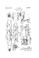
- Figure l is a view inside elevation of a ripping tool arranged and constructed in accordance with the invention.
- Fig. 2 is a view in section taken on line 11-11 of Fig. 1;
- Fig. 3 is a partial top plan-view of the tool shown in Fig. 1; I
- Fig. 4 is a fragmentary enlarged view in side elevation of the tool shown in Fig. 1;
- Fig. 5 illustrates a cotter pin employed for holding a. latch embodied in the tool in inoperative position
- Fig. 6 is a partial view in section of two pipe sections joined at adjacent ends by a pipe coupling, the pipes forming a part of a well casing; and, I
- Fig. 7 is a fragmentary viewof a tool body and a stationary cutting tool mounted thereon.
- a ripping tool 1 is shown, opposite ends 2 and 3 thereof beingthreaded so that the tool may be attached to a tool blockv (not I shown.) forming part of the mechanism (not shown) employed'for raising and lowering the tool in a well casing.
- the tool 1 may be provided with wrench flats 4 and 5 to which a wrench may be applied when the tool is to be attached to its tool block.
- each end of the tool 1 When one end of the tool 1 is attached to a tool block the other end may be protected by a cap 6 that has screw thread engagement with the end to be protected.
- the cap 6 may be locked in place by means of a pin 7 that passes through the cap and registers with a groove 8 in the end of the tool As shown each end of the tool 1 is provided with a groove 8.
- the body 9 of the tool is provided with a slot 10 and within the slot a cutting tool or knife 11 is pivoted by means of a cross-pin 12.
- the pin passes through the knife at-a point near or adjacent to a rear bottom corner 13 thereof as shown more particularly in Fig. 4, As illustrated in the drawings, the cutting tool or knife 11 is placed at one end of the slot.
- This end of the slot 10 is provided with an inclined wall 15 that cooperates with an end wall '17 of the cutting tool 11 to limit the turning movement thereof in one directionabout the cross-pin 12.
- the end wall 17, as shown in Fig. 1, slopes away from the inclined wall 15 so as to provide sufficient clearance to permit turning of the cutting tool about the pin 12 to cutting or ripping position.
- the slope of the walls 15 and 17 may be varied asrequirements or necessitydictates, being mainly used to absorb part of the pressure on cross-pin 12;
- a multiple leaf spring 18 of the cantilever type is mounted in the slot and secured to the body 9 by bolts 19 at a point adjacent to the opposite end of the slot from which the knife or cutting tool 11 is mounted.
- the free end of the spring 18 bears against the underside of the knife or cutting tool 11 and tends to force the tool into the position shown in Figs. 1, 2'and 4 with the edge or end wall 17 abutting against the inclined face 15 ofthe body within the slot 10.
- the end wall 17 of the cutting tool 11 abuts against the inclined wall 15 of the body, the tool is in its maximum cutting or ripping position.
- a latch 20 pivoted within the slot 10 by a pin 21 normally holds the knife or cutting tool 11 in inoperative position with a cutting edge 22 of the knife or tool 11 within the body.
- This inoperative position is illus- 'trated in broken lines in Fig. 1, wherein the knife or cutting tool is held within the body 9 by the latch.
- a ledge or shoulder 23 of the latch engages a ledge shoulder or catch 24 on the knife as illustrated in Fig. 4.
- a portion of the latch 20 is of substantially U-shape and straddles the leaf spring 18 in order that the free end of the spring may move up or down.
- a spring trip member 26 is pivotally connected by means of a pin 27.
- the trip member 26 is of substantially U-shape and straddles a pin 29 that extends through the body 9 of the tool.
- the pin 29 acts as a guide during movement of the spring and also as a support therefor so as to confine its movement within and longitudinally of the slot 10.
- the free end 30 of the spring trip member 26 normally lies outside of the body as shown in Figs. 1 and 2.
- Spring guides 31 and 32 are secured to the sides of the body 9 and 10 to hold the body centrally within the casing or tubing in which it is to operate.
- the contour of the tubing or casing is indicated by broken lines at 33 in Fig. 2 of the drawings.
- FIG. 6 of the drawings twosections 35 and 36 of a casing connected together by a coupling 37 are shown. The adjacent ends of the casing are separated and held separated by the coupling 37 that has screw thread engagement with the sections 35 and 36.
- the section 36 of the casing may be considered for purposes of illustration as the upper casing section and section 35 as the lower casing section, and that section 36 extends from the surface of the ground downwardly to lower section 35.
- the tool 1 Since the distance from the walking beam (not shown) to the surface of the ground is shorter than the length of pipe section 36, it being the first section at the top of the well hole, it is not possible to utilize the tool 1 as a fishing tool to remove the section of pipe extending downwardly from the surface of the ground.
- the tool since the tool is so designed that it will not catch on the pipe sections when knife edge 22 is pointing downwardly and the tool is being raised, the first section of pipe, or'the one running to the surface of the ground, may be loosened from its coupling by ripping or splitting downwardly the upper end of section 35. When this has been done, the tool is withdrawn from the casing section 36. Section 36 may then be pulled out of the well hole by the usual implements employed for this purpose.
- the tool 1 is reversed end for end and attached to the cable.
- knife edge 22 will be pointing upwardly so that the ripping or splitting of well casing sections is accomplished by jolting the tool upwardly.
- the knife 11 is always unlatched. The operation of the tool may best be understood from the following explanation.
- the well driller or operator lets down the cable or line (not shown) with the ripper attached thereto, end 2 of the tool being lowermost.
- the ripper 1 arrives at the lower end of the first section of a casing which it is desired to rip, and loosened from its coupling, the ripper is let down past the coupling and raised up.
- the free end 30 of the spring trip member 26 will collide with or catch onto the lower end of the up permost casing section within the coupling. The spring 26 will, therefore, be held stationary as the ripping tool 1 continues to move upwardly.
- the knife or cutting tool 11 is unlatched and extended to cutting position as shown in Fig. 4, the cutting edge 22 thereof no lies within the coupling 37 between the lower end of the upper casing section and the up perrnost end of the casing section immediately below it.
- the ripper down ward By jolting the ripper down ward, the upper end of the lower casing section will be split or ripped at the point where it is attached to the coupling 37.
- the ripping tool 1 is withdrawn from the casing and the upper- 10 of the body.
- Tool 1 is then reversed end for end on the cable or line from which it is suspended.
- the end 2 thereof is attached to the cable or line which the driller or operator lets down into the well casing.
- the latch 20 is secured in the position shown in Fig. 4 of the drawings by a cotter pin 39 (see Fig. 5) that passes through the body 9 of the tool 1.
- the spring member 26 By holding the spring member 26 with the pin 39, shownalso in broken lines in F ig. 1, the free end 30 of the spring member is moved upwardly into the slot 10 of the body 9 so that it cannot engage any coupled section of casing as the tool 1 is let down again into the casing. Since the spring member 26 is held in the position indicated in Fig. 1 of the drawings, that is, in the position in which the latch 20 is shown in full lines in Fig. 4, the cutting tool or knife 11 is held in its extended or cutting position by the spring ,18.
- the ripping tool 1 is capable of use both as a ripping tool, when moving downwardly into the well casing, and as a ripping and fishing tool when reversed end for end in the casing and jolted upwardly.
- a cutting tool 42 is stationarily mounted on the same side of the body 9 as the cutting edge 22 of the ripping tool 11 is located.
- the cutting tool 42 is located at the opposite end of the slot
- the cutting edge 43 of the tool 42 trims or cuts away the chips and ragged edges formed in the lower casing section 35 by the cutting tool 11. Therefore,
- a ripping tool for well casings com; prising a body having ,a longitudinally; .exs tendingslot therein, a cutting tool in. one end of said slot pivotally mounted therein for ripping when said tool is moved'in; one direction, and a cutting tool stationarily mounted on said body at the other end of the slot, said latter tool being so located that as the body moves in the opposite direction, it will traverse the path of travel of the pivotally mounted tool so as to. remove any obstruction caused by said pivoted cutter.
- a ripping tool for well casings comprising a body having a longitudinally extending slot therein,.a cutting tool in one. end of said slot pivotally mounted therein, and a cutting tool astationarilymounted on said. body at the other end of the slot and having a cutting edge pointing towards the cuttingedge of the pivotally mounted tool,said latter tool being so located that as the body moves, it traverses the path of travel of the pivotally mounted tool.
- Areversible well casing ripping tool comprising a body'portion having an elongated longitudinal slot, a ripper .knife located at one end of said slot and pivotally mountedtherein,a catch on said knife positioned within the slot, means urging the knife to ripping position, a latch within said slot and pivotally mounted therein, said latch having a shoulder to engage said catch and hold said knife wholly within the slot, a resilient latch trip of U-shape having one leg thereof pivotally connected to the latch and the other leg having its free end bent outwardly so that it lies outside of the slot when,
- a resilient latch trip of U-shape having one leg thereofpivotally connected to the latch and the other leg having its free end bent outwardly so that it lies outside of the slot when the shoulder of the latch engages the catch on the knife, a pin extending across the slot and between the legs of said latch trip for supporting the same so that it may move longitudinally of the slot when operating said latch, and means for holding said latch trip wholly within the slot when the tool is arranged to rip upwardly.
- a ripping tool for well casings comm prising a body having a longitudinally extending slot therein, a cutting tool pivotally mounted in said slot, and a cutting tool stationarily mounted on said body and having a cutting edge pointing towards the cutting edge of the pivotally mounted tool, said latter tool being so located that as the body moves, it traverses the path of travel of the pivotally mounted tool.
- a reversible well casing ripping tool 5 comprising a body portion having an elongated longitudinal slot, a ripper knife located in said slot and pivotally mounted therein, a catch on said knife positioned within the slot, means urging the knife to ripping an position, a latch within said slot and pivotally mounted therein, said latch having a shoulder to engage said catch and hold said knife wholly within the slot, a resilient latch trip pivotally connected to the latch, a por- 36 tion of said latch trip being bent outwardly so that it lies outside of the slot when the shoulder of the latch engages the catch on the knife, and means for supporting said latch trip so that it may move longitudinally of the 40 slot when operating said latch.
Landscapes
- Life Sciences & Earth Sciences (AREA)
- Engineering & Computer Science (AREA)
- Geology (AREA)
- Mining & Mineral Resources (AREA)
- Physics & Mathematics (AREA)
- Environmental & Geological Engineering (AREA)
- Fluid Mechanics (AREA)
- General Life Sciences & Earth Sciences (AREA)
- Geochemistry & Mineralogy (AREA)
- Knives (AREA)
Description
- March 22, 1932. SPANG 1,850,185
RIPPER FOR WELLv CASINGS Filed Feb; 27, 1930 E: 58in) mm. 4 s, 11%| 0 wmwweam Patented Mar. 22, 1932 PATENT OFFICE- FERDINAND J. srA'NQor BUTLER, PENNSYLVANIA RIPPER FOR WELL CASINGS Application filed February 27, 1930. Serial No. 431,770.
This invention relates to ripping tools for well casings. Casings for wells, oil wells for example,
usually comprise a plurality of pipe sections @joined at adjacent ends by couplings. I These casings are intended to be removed at some time or another from the well in which they are located. Great diiiiculty is often encountered in removingthe casings because of the earth, or strata surrounding the casings, caving in and holding them fast in the well.
hen it is found that such casings are stuck or held fast in a well, certain sections must be sacrificed in order to save the other sections and in such case it is customary to rip up some of the sections before any of the sections can be removed.
.An object of this invention is, therefore, to provide a ripping tool for well casings that shall be simple in construction, efiicient in operation and easily manufactured and installed. I
Another object is to provide a tool of the type referred to above that may be utilized to rip a casing when moving in one'direction and as a fishing tool when reversed end for end inthe casing and moving in the opposite direction.
A further object of the invention is to unlatch a cutting tool of a casing ripper when the tool is in a selected station or position in the casing. I
Other objects of the invention will, in part, be obvious and will, in part, be apparent from the following description-taken in conjunction with the accompanying drawings in which: I
Figure l is a view inside elevation of a ripping tool arranged and constructed in accordance with the invention;
" Fig. 2 is a view in section taken on line 11-11 of Fig. 1;
Fig. 3 is a partial top plan-view of the tool shown in Fig. 1; I
Fig. 4 is a fragmentary enlarged view in side elevation of the tool shown in Fig. 1;
Fig. 5 illustrates a cotter pin employed for holding a. latch embodied in the tool in inoperative position; o
Fig. 6 is a partial view in section of two pipe sections joined at adjacent ends by a pipe coupling, the pipes forming a part of a well casing; and, I
Fig. 7 is a fragmentary viewof a tool body and a stationary cutting tool mounted thereon. Throughout the drawings and the specification like reference'characters indicate lik parts. I r In the drawings, with particular reference to Fig. 1, a ripping tool 1 is shown, opposite ends 2 and 3 thereof beingthreaded so that the tool may be attached to a tool blockv (not I shown.) forming part of the mechanism (not shown) employed'for raising and lowering the tool in a well casing. The tool 1 may be provided with wrench flats 4 and 5 to which a wrench may be applied when the tool is to be attached to its tool block.
When one end of the tool 1 is attached to a tool block the other end may be protected by a cap 6 that has screw thread engagement with the end to be protected. The cap 6 may be locked in place by means of a pin 7 that passes through the cap and registers with a groove 8 in the end of the tool As shown each end of the tool 1 is provided with a groove 8.
The body 9 of the tool is provided with a slot 10 and within the slot a cutting tool or knife 11 is pivoted by means of a cross-pin 12. The pin passes through the knife at-a point near or adjacent to a rear bottom corner 13 thereof as shown more particularly in Fig. 4, As illustrated in the drawings, the cutting tool or knife 11 is placed at one end of the slot. This end of the slot 10 is provided with an inclined wall 15 that cooperates with an end wall '17 of the cutting tool 11 to limit the turning movement thereof in one directionabout the cross-pin 12. The end wall 17, as shown in Fig. 1, slopes away from the inclined wall 15 so as to provide sufficient clearance to permit turning of the cutting tool about the pin 12 to cutting or ripping position. The slope of the walls 15 and 17 may be varied asrequirements or necessitydictates, being mainly used to absorb part of the pressure on cross-pin 12;
A multiple leaf spring 18 of the cantilever type is mounted in the slot and secured to the body 9 by bolts 19 at a point adjacent to the opposite end of the slot from which the knife or cutting tool 11 is mounted. The free end of the spring 18 bears against the underside of the knife or cutting tool 11 and tends to force the tool into the position shown in Figs. 1, 2'and 4 with the edge or end wall 17 abutting against the inclined face 15 ofthe body within the slot 10. When the end wall 17 of the cutting tool 11 abuts against the inclined wall 15 of the body, the tool is in its maximum cutting or ripping position.
A latch 20 pivoted within the slot 10 by a pin 21 normally holds the knife or cutting tool 11 in inoperative position with a cutting edge 22 of the knife or tool 11 within the body. This inoperative position is illus- 'trated in broken lines in Fig. 1, wherein the knife or cutting tool is held within the body 9 by the latch. hen the cutting tool or knife 11 is held in inoperative position, a ledge or shoulder 23 of the latch engages a ledge shoulder or catch 24 on the knife as illustrated in Fig. 4. As shown a portion of the latch 20 is of substantially U-shape and straddles the leaf spring 18 in order that the free end of the spring may move up or down.
To the free end of the latch 20, a spring trip member 26 is pivotally connected by means of a pin 27. The trip member 26 is of substantially U-shape and straddles a pin 29 that extends through the body 9 of the tool. The pin 29 acts as a guide during movement of the spring and also as a support therefor so as to confine its movement within and longitudinally of the slot 10. The free end 30 of the spring trip member 26 normally lies outside of the body as shown in Figs. 1 and 2.
In Fig. 6 of the drawings twosections 35 and 36 of a casing connected together by a coupling 37 are shown. The adjacent ends of the casing are separated and held separated by the coupling 37 that has screw thread engagement with the sections 35 and 36. The section 36 of the casing may be considered for purposes of illustration as the upper casing section and section 35 as the lower casing section, and that section 36 extends from the surface of the ground downwardly to lower section 35.
Since the distance from the walking beam (not shown) to the surface of the ground is shorter than the length of pipe section 36, it being the first section at the top of the well hole, it is not possible to utilize the tool 1 as a fishing tool to remove the section of pipe extending downwardly from the surface of the ground.
However, since the tool is so designed that it will not catch on the pipe sections when knife edge 22 is pointing downwardly and the tool is being raised, the first section of pipe, or'the one running to the surface of the ground, may be loosened from its coupling by ripping or splitting downwardly the upper end of section 35. When this has been done, the tool is withdrawn from the casing section 36. Section 36 may then be pulled out of the well hole by the usual implements employed for this purpose.
After the top section of pipe has been removed, the remaining pipe sections which are below the surface of the ground must be loosened and pulled or fished to the top of the well hole or to the surface of the ground. To accomplish this purpose, the tool 1 is reversed end for end and attached to the cable. When so reversed knife edge 22 will be pointing upwardly so that the ripping or splitting of well casing sections is accomplished by jolting the tool upwardly. In ripping or splitting upwardly, the knife 11 is always unlatched. The operation of the tool may best be understood from the following explanation.
In utilizing the casing ripper 1 for removing casing from a well, the well driller or operator lets down the cable or line (not shown) with the ripper attached thereto, end 2 of the tool being lowermost. ,VVhen the ripper 1 arrives at the lower end of the first section of a casing which it is desired to rip, and loosened from its coupling, the ripper is let down past the coupling and raised up. In raising or. moving upwardly, the free end 30 of the spring trip member 26 will collide with or catch onto the lower end of the up permost casing section within the coupling. The spring 26 will, therefore, be held stationary as the ripping tool 1 continues to move upwardly. This causes the latch 20 to turn 5310 about its pivot 21 to the position shown in Fig. 4 of the drawings whereby the cutting tool or knife 11 is released to cutting or operative position. The cutting tool or knife 11 is moved to operative position by the can tilever spring 18 as indicated in Fig. 4 of the drawings.
WVhen the knife or cutting tool 11 is unlatched and extended to cutting position as shown in Fig. 4, the cutting edge 22 thereof no lies within the coupling 37 between the lower end of the upper casing section and the up perrnost end of the casing section immediately below it. By jolting the ripper down ward, the upper end of the lower casing section will be split or ripped at the point where it is attached to the coupling 37.
After the upper end of the lower casing section 35 has been ripped, the ripping tool 1 is withdrawn from the casing and the upper- 10 of the body.
most section removed from the well hole. Tool 1 is then reversed end for end on the cable or line from which it is suspended. When tool 1 has been reversed the end 2 thereof is attached to the cable or line which the driller or operator lets down into the well casing. Before the ripping tool in its reversed position is let down again intothe casing, the latch 20 is secured in the position shown in Fig. 4 of the drawings by a cotter pin 39 (see Fig. 5) that passes through the body 9 of the tool 1. By holding the spring member 26 with the pin 39, shownalso in broken lines in F ig. 1, the free end 30 of the spring member is moved upwardly into the slot 10 of the body 9 so that it cannot engage any coupled section of casing as the tool 1 is let down again into the casing. Since the spring member 26 is held in the position indicated in Fig. 1 of the drawings, that is, in the position in which the latch 20 is shown in full lines in Fig. 4, the cutting tool or knife 11 is held in its extended or cutting position by the spring ,18.
As the tool 1 is let down again into the easing it is stopped when the cutting edge 22 of the knife is adjacent a coupling 37 at the lower end of casing section 35. Upon raising the tool 1 the cutting edge 22 engages the lower end of section 35 of the casing and by jolting the tool upward the lower end of this section is ripped free. As the lower end of section 35 is ripped, the metal of the casing is forced inwardly of the casing towards the center thereof so as to form a seat for the face 40 of the knife or cutting tool 11. As the jolting of the tool continues, the lower end of section 35 will finally break away from its coupling 37 and since this section will then be resting on the face 40 of the cutting tool, it may be fished out of the well by-the ripping tool 1.
It is, therefore, obvious from the above description that the ripping tool 1 is capable of use both as a ripping tool, when moving downwardly into the well casing, and as a ripping and fishing tool when reversed end for end in the casing and jolted upwardly.
. In order that chips and fragmentary edges formed on the upper end of the lower casing section 35 may not interfere with the passage of the cutting tool 1 when it is let down into the casing after having beenreversed end for end so as to be in position to rip the lower end of casing section 35, a cutting tool 42 is stationarily mounted on the same side of the body 9 as the cutting edge 22 of the ripping tool 11 is located. The cutting tool 42, however, is located at the opposite end of the slot As the ripper 1 is withdrawn from the casing, after the upper end of easing section 35 has been ripped, the cutting edge 43 of the tool 42 trims or cuts away the chips and ragged edges formed in the lower casing section 35 by the cutting tool 11. Therefore,
when the tool 1 has beenireversedand let down into-the casingagain, the ripped joint While various changes;and modifications may be made in the ripping tool herein dis- I closed without departing from the'spirit and the scope of the invention, it is, desired that only such limitations shall be'placed on the invention as are imposed by. theprior art and the'appended claims. v f
What I claim as new and desire to secure by Letters Patent is: i u 1. A ripping tool for well casings com; prising a body having ,a longitudinally; .exs tendingslot therein, a cutting tool in. one end of said slot pivotally mounted therein for ripping when said tool is moved'in; one direction, and a cutting tool stationarily mounted on said body at the other end of the slot, said latter tool being so located that as the body moves in the opposite direction, it will traverse the path of travel of the pivotally mounted tool so as to. remove any obstruction caused by said pivoted cutter. I
p 2. A ripping tool for well casings comprising a body having a longitudinally extending slot therein,.a cutting tool in one. end of said slot pivotally mounted therein, and a cutting tool astationarilymounted on said. body at the other end of the slot and having a cutting edge pointing towards the cuttingedge of the pivotally mounted tool,said latter tool being so located that as the body moves, it traverses the path of travel of the pivotally mounted tool. V t I 3., Areversible well casing ripping tool comprising a body'portion having an elongated longitudinal slot, a ripper .knife located at one end of said slot and pivotally mountedtherein,a catch on said knife positioned within the slot, means urging the knife to ripping position, a latch within said slot and pivotally mounted therein, said latch having a shoulder to engage said catch and hold said knife wholly within the slot, a resilient latch trip of U-shape having one leg thereof pivotally connected to the latch and the other leg having its free end bent outwardly so that it lies outside of the slot when,
the shoulder of the latch engages the catch on the knife, and a pin extending across the slot and between the legs of said latch trip jto engage said catch and hold said knife wholly within the slot, a resilient latch trip of U-shape having one leg thereofpivotally connected to the latch and the other leg having its free end bent outwardly so that it lies outside of the slot when the shoulder of the latch engages the catch on the knife, a pin extending across the slot and between the legs of said latch trip for supporting the same so that it may move longitudinally of the slot when operating said latch, and means for holding said latch trip wholly within the slot when the tool is arranged to rip upwardly.
5. A ripping tool for well casings comm prising a body having a longitudinally extending slot therein, a cutting tool pivotally mounted in said slot, and a cutting tool stationarily mounted on said body and having a cutting edge pointing towards the cutting edge of the pivotally mounted tool, said latter tool being so located that as the body moves, it traverses the path of travel of the pivotally mounted tool. p 6. A reversible well casing ripping tool 5 comprising a body portion having an elongated longitudinal slot, a ripper knife located in said slot and pivotally mounted therein, a catch on said knife positioned within the slot, means urging the knife to ripping an position, a latch within said slot and pivotally mounted therein, said latch having a shoulder to engage said catch and hold said knife wholly within the slot, a resilient latch trip pivotally connected to the latch, a por- 36 tion of said latch trip being bent outwardly so that it lies outside of the slot when the shoulder of the latch engages the catch on the knife, and means for supporting said latch trip so that it may move longitudinally of the 40 slot when operating said latch.
In testimony whereof, I have hereunto subscribed my name this 19th day of February, 1930. Y
FERDINAND J. SPANG.
Priority Applications (1)
| Application Number | Priority Date | Filing Date | Title |
|---|---|---|---|
| US431770A US1850185A (en) | 1930-02-27 | 1930-02-27 | Ripper for well casings |
Applications Claiming Priority (1)
| Application Number | Priority Date | Filing Date | Title |
|---|---|---|---|
| US431770A US1850185A (en) | 1930-02-27 | 1930-02-27 | Ripper for well casings |
Publications (1)
| Publication Number | Publication Date |
|---|---|
| US1850185A true US1850185A (en) | 1932-03-22 |
Family
ID=23713350
Family Applications (1)
| Application Number | Title | Priority Date | Filing Date |
|---|---|---|---|
| US431770A Expired - Lifetime US1850185A (en) | 1930-02-27 | 1930-02-27 | Ripper for well casings |
Country Status (1)
| Country | Link |
|---|---|
| US (1) | US1850185A (en) |
-
1930
- 1930-02-27 US US431770A patent/US1850185A/en not_active Expired - Lifetime
Similar Documents
| Publication | Publication Date | Title |
|---|---|---|
| US2030722A (en) | Cutter assembly | |
| US2105722A (en) | Well-boring apparatus | |
| US2103622A (en) | Side tracking apparatus | |
| US1789993A (en) | Casing ripper | |
| US1879127A (en) | Combination rolling and scraping cutter bit | |
| US3556233A (en) | Well reamer with extensible and retractable reamer elements | |
| US2196940A (en) | Deflecting bit | |
| US2839270A (en) | Releasable connections for drain hole drilling equipment | |
| US2969838A (en) | Combination shearing and shut-off ram | |
| US2330083A (en) | Retractable drill bit | |
| US3105555A (en) | Casing scraper | |
| US2638320A (en) | Pipe cutter or reamer for use on crooked pipe | |
| US3876001A (en) | Kickover tool | |
| US1850185A (en) | Ripper for well casings | |
| US2710170A (en) | Apparatus for deflecting and reaming drill holes | |
| US3174548A (en) | Combination washover tool, pipe cutter and retriever | |
| US2940522A (en) | Cutting tool | |
| USRE21824E (en) | An apparatus fob and a method of | |
| US2142859A (en) | Well-bore deflecting tool | |
| US3111989A (en) | Perforator for well flow conductors | |
| US2705998A (en) | Ripper for well casing | |
| US2284580A (en) | Well drilling bit | |
| US904344A (en) | Underreamer. | |
| US1614840A (en) | Cutter | |
| GB1579520A (en) | Well tool with a pawl |