US1850180A - Sign - Google Patents
Sign Download PDFInfo
- Publication number
- US1850180A US1850180A US563070A US56307031A US1850180A US 1850180 A US1850180 A US 1850180A US 563070 A US563070 A US 563070A US 56307031 A US56307031 A US 56307031A US 1850180 A US1850180 A US 1850180A
- Authority
- US
- United States
- Prior art keywords
- frame
- sections
- beveled
- sign
- rectangular
- Prior art date
- Legal status (The legal status is an assumption and is not a legal conclusion. Google has not performed a legal analysis and makes no representation as to the accuracy of the status listed.)
- Expired - Lifetime
Links
Images

Classifications
-
- G—PHYSICS
- G09—EDUCATION; CRYPTOGRAPHY; DISPLAY; ADVERTISING; SEALS
- G09F—DISPLAYING; ADVERTISING; SIGNS; LABELS OR NAME-PLATES; SEALS
- G09F1/00—Cardboard or like show-cards of foldable or flexible material
- G09F1/10—Supports or holders for show-cards
- G09F1/12—Frames therefor
Definitions
- This invention relates to signs. and is more particularly directed to a new andimproved g'together signs of. the type now in general use as,- forexample, those used along roads'and in similar exposed positions. H I
- Another 'ob-jectof the invention is to provide a sign put together in a newand improved manner and simulating a more expensive: construe:- tion
- FIG. 6 is a view-illustrating the positions of the different sheath sections relascribed and particularly pointed out the The annexed drawings and 'the following n detail certainmech-' closed means constituting, however, but one of various mechanical; forms in which the le of the invention may be used.
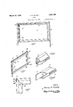
- Fig. l is a front elevationof a sign constructed according to the improved manner;
- Fig. 2 is a perspective of the framework of the sign;
- Fig. 3 is a perspective of a pair of sheath sectionsforthe sign showing one end thereof;
- Fig.4 is a. perspective showing the opposite ends of'the sheath sections ,Fig 5. is an enlarged front elevation of one corner tive to one another as they are to be placed on a'frame
- Fig. 7 is aview similar to Fig. 6' showing a modified form of sheath section;
- Fig.- 8 is a perspective of a modified framework for asign intended for. usewithrthe form of sheath. sections illustrated in Fig. 7
- 'and Fig. 9 is axview illustrating one end of a' and 5.
- an improved. sign .of thle type referred to consists of .uprights l wuc ground. Between these uprights'is mounted a sign 2, consisting ofa'panelr3 mounted between wooden frame sections 4 and 5 which are-covered by meanso f stamped metal sheath which may be formed in any! i'provided that "they engage the wooden 'frame strips 4 sections 6 and 7, desired manner snugly agains The wooden frame, as shown in Fig. 2,
- four sides are joined together by metal pieces 12.
- xAs. illustrated, the butt joints at front and back are staggered toincrease the strength of the frame. This butt joint conadvantageous forree taining'the particular form of metal sheathing covering the frame, as will appear hereinafter.
- a groove 13 is left between'the' back and-front wood sections forthe I'GCBPtlOIl'Of nt strip 4 and In orderftogive the frame anornamental appearance and-to render the same more durable, the woodensectionsare covered by; a 7
- metal sheathing which may be givena molded contourfor decorative purposes but,tof any particular shape of which, the inven tion is not limited.
- This sheathing consists of sections'6 and 7 ⁇ in matched pairs which over the wooden frame.
- Each. section has one rectangular end 13 as indicated in Fig. 3, and onebeveled s indicated'in'Fig. 4, or the sheath may be cut with'both endsrectangular 0r withboth ends beveled,;the two kinds of sections being alternate-d. around the. frame.”
- the rectangular end is provided with a cut away portion 15 in order that it'may fit on the framewith the terminal edge 13'coincident withxa terminal edge l6-o'f one of the Wooden sections forming the frame.
- ay be molded to form rs of sections) h are continued and embedded in thethe sign willha've beveled end is so out, usually at an angle of that the beveled edge 14 coincides with a line drawn from an inner corner 17 to an outer corner 18 of the frame.
- This end of one sheath section in each pair is also provided with a tab 19 which can be bent and nailed to the frame.
- Fig. 5 is shown the manner in which the sheathing is placed over the wooden frame at one corner, a similar procedure being followed at each of the other corners.
- a rectangular end of a sheath section is first placed on the wooden frame so that its terminal edge 13 coincides with a terminal edge 16 ofthe frame, this being made possible by the cut away portion 15 which accommodates the width of the adjoining wood section, for example, section 8.
- the beveled end of another sheath section is'then slid over the sheath section first applied, so that its beveled edge 14 coincides with aline drawn between the inside and outside frame corners 17 and 18 and simulates a mortise joint at the corner.
- the tab 19 is then bent over and nailed to the side of the frame by nails 21 and 22. Due to the fact that the beveled end is placed across the front wood joint, this tab will be attached with nails 21 and 22 running transversely of the grain of the wood.
- each section has a rectangular end and a beveled end, the beveledend 14 having a tab 19.
- Each beveled end is placed adjacent the rectangular end over which it is intended to lit and the beveled ends follow each other in sequence around the frame.
- rear sheath sections are similarly disposed but do not require tabs 19.
- This arrangement of the sheath sections is adapted for use with the frame-work illustrated in Fig. 2 in which the butt joints 11 also follow in sequence around the frame, the rear joints being staggered, however, in relation to the front joints.
- FIG. 7 Another modification of the sign structure is illustrated in Figs. 7 and 8, Fig. 8 illustrating a wooden frame-work so put together that the butt joints do not follow in sequence around the frame, but in which two of the pairs of wooden strips 23 are held between other two pairs of strips againstthe sides of whichthe ends of the strips 23 abut.
- This construction of the frame permits theuse of permitting nails to be sheath sections such as shown in the arrangement depicted in Fig. 7 in which sheath sections 25 are made with both ends rectangular and co-operate with sections 26 having both ends beveled and having tabs 27 at both of these beveled ends.
- the appearance of a sign constructed in this manner will be identical with that constructed according .to the arrangement shown in Fig. 6 but the tabs 27 are positioned so that they may be nailed against the sides of the wooden strips 24, thus driven transversely into the grain of the wood as in the first modification.
- sheath sections be formed by a single operation of a stamping die.
- a blank so prepared willhave an outline at a beveled end as shown in Fig. 9 in which the blank 28 has a beveled end 29 and a tab 31.
- the opposite end may either be cut rectangular, which presents no difficulties, or may have an outline identical with theend shown, where a sheath section similar to 26 in Fig. 7 is to be prepared.
- the fiat blank can then be molded and bent to form the ornamental outline for the sign. The same blank may be bent in one direction or the other in accordance with whether a front or back section is to be made.
- tabs neednot be used on the rear sections and it will be obvious that the tab 31 may be cut off along the line 32 and, also, where a narrower blank is required for a rear section, a strip of metal may be sheared 0d the blank along the line 33. It will thus be seen that only one shape of blank may be used to form any of the sheath sections illustrated in the drawings, simple trimming operations being availed of where necessary.
- the new sign formed as described above is simple and inexpensive to make and yet is very durable as well as being highly ornamental due to the simulation of a mortise joint at the corners of the sheathing.
- the combination in the structure of a butt joint frame-work together with the sheathing of the kind described results in a strong but inexpensive structure due to the manner in which the tabs 19 may be attached to the frame.
- the combination which comprises metal sheathing placed over a frame, said sheathing consisting of sections having rectangular ends and beveled 5 ends, each of said beveled ends fitting over a rectangular end on said frame.
- the combination which comprises molded metal sheathing placed over a frame, said sheathing consisting of sections having rectangular ends and beveled ends, each of said beveled ends fitting over a rectangular end on said frame and being attached to said frame.
- the combination whichcomprises a panel-engaging frame, and molded metal sheathing enclosing said frame, said sheathing consisting of sections having rectangular ends and beveled ends, each of said beveled endsfitting over a rectangular end on said frame.
- a sign structure which comprises a woodenframe and molded metal sheathing covering said frame, said sheathing consisting of sections having rectangular ends and beveled ends, and said sections being placed on said frame with said beveled ends covering said rectangular ends to simulate a miter j oint.
- a sign structure which comprises a wooden frame having butt joints, and formed metal sheathing covering said frame, said sheathing consisting of sections having one rectangular end and one beveled end, each beveled end fitting over a rectangular end and having a tab bent over and nailed to the side of said frame.
- a sign structure which comprises a wooden frame composed of a plurality of sections joined together by butt joints, formed metal sheathing covering said frame, said sheathing consisting of sections having rectangular ends and beveled ends, said beveled ends fitting over said rectangular ends with their terminal edges coinciding with a line between the inner and outer corners of said frame.
- a sign structure which comprises a wooden frame composed of a plurality of sections joined togetherby butt Joints, molded metal sheathing covering said frame, said sheathing consisting of sections having rectangular ends and beveled ends, said sections being placed on said frame with said beveled ends covering said rectangular ends to simulate a miter joint, and said beveled ends having tabs bent over and nailed to said frame transversely'ofthe grain of the wood.
- said frame said sheathing consisting of sections having rectangular ends and beveled ends, said beveled ends fitting over said rectangular ends and tabs bent over and nailed to the sides of said frame.
- sheathing covering said frame, said sheathing consisting of'sections having rectangular ends and beveled ends,
- a sign structure which comprises a wooden frame composed of a plurality of sections joined together by butt joints, molded metal sheathing covering said frame, said sheathing consisting of sections having rectangular ends and beveled ends, said rectangular ends being placed with their terminal edges coinciding with the terminal edges of a frame section and said beveled ends being placed over said rectangular ends with their terminal edges lying on a line between the inner and outer corners of said frame.
- a sign structure which comprises a wooden frame composed of a plurality of sections joined together by butt joints and molded metal sheathing enclosing said frame, said sheathing consisting 1 and said beveledends being placed over said said beveled ends fit- .tingover said rectangular ends, and tabs
Description
March; 22, 1932. PINNEY SIGN Filed Sept. 16 1951 2 Sheets-Sheet INVEVTOR.
- flurry fl. P/hflf] BY I -'-the panel carrying theadvertising or other @110 -means for securin Patented Mar. 22,. 1932.
' imny mrINNEY, on CLEVELAND, onro sren Application filed September 1 This invention relates to signs. and is more particularly directed to a new andimproved g'together signs of. the type now in general use as,- forexample, those used along roads'and in similar exposed positions. H I
Itis desirable in signsof this character that the construction be durable and that matter be securely held while, atthesame time, preserving a pleasing-and decorative accordingly, p vid'e a sign which 1s durable and decoratlve appearance forthesignas a whole. vAn inexpensive construction embodying the foregoing features-is alsoarequisite since these signs are put out inlarge numbers. It is,
an object of the invention to proas-wellas inexpensive toconstruct. Another 'ob-jectof the invention is to provide a sign put together in a newand improved manner and simulating a more expensive: construe:- tion To the accomplishment of the foregoing and related ends, said invention, then,
consists of the means hereinafter fully declaims.
' description set forth i 'anism embodying the invention, such dis .princip of the sign Fig. 6 is a view-illustrating the positions of the different sheath sections relascribed and particularly pointed out the The annexed drawings and 'the following n detail certainmech-' closed means constituting, however, but one of various mechanical; forms in which the le of the invention may be used. In said annexed drawings:
Fig. l is a front elevationof a sign constructed according to the improved manner; Fig. 2 is a perspective of the framework of the sign; Fig. 3 ,is a perspective of a pair of sheath sectionsforthe sign showing one end thereof; Fig.4 is a. perspective showing the opposite ends of'the sheath sections ,Fig 5. is an enlarged front elevation of one corner tive to one another as they are to be placed on a'frame Fig. 7 is aview similar to Fig. 6' showing a modified form of sheath section;
Fig.- 8 is a perspective of a modified framework for asign intended for. usewithrthe form of sheath. sections illustrated in Fig. 7
'and Fig. 9 is axview illustrating one end of a' and 5.
consists of a plurality of pai struction is particularly the. sign. panel 3.
are adapted to fit snugly end 14, a sectionsa, 1931'. Seria1No."563;070.
flat stamping whichm a sheath'section. a I, u
Referring to Fig. 1, an improved. sign .of thle; type referred to consists of .uprights l wuc ground. Between these uprights'is mounted a sign 2, consisting ofa'panelr3 mounted between wooden frame sections 4 and 5 which are-covered by meanso f stamped metal sheath which may be formed in any!" i'provided that "they engage the wooden 'frame strips 4 sections 6 and 7, desired manner snugly agains The wooden frame, as shown in Fig. 2,
each pair constituted by a fro a rear strip 5. Ordinarily, four sides," but it will be obvious that a greaternumber of sides maybe used. Thesides 8 and 9 arejoinedtogether by means of butt joints as at 11 and are held together by metal pieces 12. xAs. illustrated, the butt joints at front and back are staggered toincrease the strength of the frame. This butt joint conadvantageous forree taining'the particular form of metal sheathing covering the frame, as will appear hereinafter. A groove 13 is left between'the' back and-front wood sections forthe I'GCBPtlOIl'Of nt strip 4 and In orderftogive the frame anornamental appearance and-to render the same more durable, the woodensectionsare covered by; a 7
metal sheathing which may be givena molded contourfor decorative purposes but,tof any particular shape of which, the inven tion is not limited. This sheathing consists of sections'6 and 7 {in matched pairs which over the wooden frame. Each. section has one rectangular end 13 as indicated in Fig. 3, and onebeveled s indicated'in'Fig. 4, or the sheath may be cut with'both endsrectangular 0r withboth ends beveled,;the two kinds of sections being alternate-d. around the. frame." The rectangular end is provided with a cut away portion 15 in order that it'may fit on the framewith the terminal edge 13'coincident withxa terminal edge l6-o'f one of the Wooden sections forming the frame. Th
ay be: molded to form rs of sections) h are continued and embedded in thethe sign willha've beveled end is so out, usually at an angle of that the beveled edge 14 coincides with a line drawn from an inner corner 17 to an outer corner 18 of the frame. This end of one sheath section in each pair is also provided with a tab 19 which can be bent and nailed to the frame. In Fig. 5 is shown the manner in which the sheathing is placed over the wooden frame at one corner, a similar procedure being followed at each of the other corners. A rectangular end of a sheath section is first placed on the wooden frame so that its terminal edge 13 coincides with a terminal edge 16 ofthe frame, this being made possible by the cut away portion 15 which accommodates the width of the adjoining wood section, for example, section 8. The beveled end of another sheath section is'then slid over the sheath section first applied, so that its beveled edge 14 coincides with aline drawn between the inside and outside frame corners 17 and 18 and simulates a mortise joint at the corner. The tab 19 is then bent over and nailed to the side of the frame by nails 21 and 22. Due to the fact that the beveled end is placed across the front wood joint, this tab will be attached with nails 21 and 22 running transversely of the grain of the wood. This is one of the improved features of the sign construction since the nails are better retained in this way than if they were driven into the end of the grain, and there is also less chance of splitting the wood. Of course, additional nails will be used to attach the sheathing to the frame along the sides of the latter.
The manner in which the sheath sections will be disposed on the wooden frame shown in Fig. 2 is illustrated in Fig. 6. The sections 6 shown therein are not attached to the frame but are placed adjacent one another for illustrative purposes only. It will be seen that each section has a rectangular end and a beveled end, the beveledend 14 having a tab 19. Each beveled endis placed adjacent the rectangular end over which it is intended to lit and the beveled ends follow each other in sequence around the frame. The
rear sheath sections are similarly disposed but do not require tabs 19. This arrangement of the sheath sections is adapted for use with the frame-work illustrated in Fig. 2 in which the butt joints 11 also follow in sequence around the frame, the rear joints being staggered, however, in relation to the front joints.
Another modification of the sign structure is illustrated in Figs. 7 and 8, Fig. 8 illustrating a wooden frame-work so put together that the butt joints do not follow in sequence around the frame, but in which two of the pairs of wooden strips 23 are held between other two pairs of strips againstthe sides of whichthe ends of the strips 23 abut. This construction of the frame permits theuse of permitting nails to be sheath sections such as shown in the arrangement depicted in Fig. 7 in which sheath sections 25 are made with both ends rectangular and co-operate with sections 26 having both ends beveled and having tabs 27 at both of these beveled ends. The appearance of a sign constructed in this manner will be identical with that constructed according .to the arrangement shown in Fig. 6 but the tabs 27 are positioned so that they may be nailed against the sides of the wooden strips 24, thus driven transversely into the grain of the wood as in the first modification.
In order thatthese signs may be constructed with a minimum of expense, it is necessary that the sheath sections be formed by a single operation of a stamping die. A blank so prepared willhave an outline at a beveled end as shown in Fig. 9 in which the blank 28 has a beveled end 29 and a tab 31. The opposite end may either be cut rectangular, which presents no difficulties, or may have an outline identical with theend shown, where a sheath section similar to 26 in Fig. 7 is to be prepared. The fiat blank can then be molded and bent to form the ornamental outline for the sign. The same blank may be bent in one direction or the other in accordance with whether a front or back section is to be made. Of course, tabs neednot be used on the rear sections and it will be obvious that the tab 31 may be cut off along the line 32 and, also, where a narrower blank is required for a rear section, a strip of metal may be sheared 0d the blank along the line 33. It will thus be seen that only one shape of blank may be used to form any of the sheath sections illustrated in the drawings, simple trimming operations being availed of where necessary.
The new sign formed as described above is simple and inexpensive to make and yet is very durable as well as being highly ornamental due to the simulation of a mortise joint at the corners of the sheathing. The combination in the structure of a butt joint frame-work together with the sheathing of the kind described results in a strong but inexpensive structure due to the manner in which the tabs 19 may be attached to the frame.
Other modes of applying the principle of my invention may be employed instead of the one explained, change being made as regards the mechanism herein disclosed, provided the means stated by any of the following claims or the equivalent of such stated means be employed.
I therefore particularly point out and distinctly claim as my invention:
1. In a sign structure, the combination which comprises metal sheathing placed over a frame, said sheathing consisting of sections having rectangular ends and beveled 5 ends, each of said beveled ends fitting over a rectangular end on said frame. j
2. Ina sign structure, the combination which comprises molded metal sheathing placed over a frame, said sheathing consisting of sections having rectangular ends and beveled ends, each of said beveled ends fitting over a rectangular end on said frame and being attached to said frame.
3. In a sign structure, the combination whichcomprises a panel-engaging frame, and molded metal sheathing enclosing said frame, said sheathing consisting of sections having rectangular ends and beveled ends, each of said beveled endsfitting over a rectangular end on said frame. I a
4. In a sign structure, the combination which comprises a woodenframe and molded metal sheathing covering said frame, said sheathing consisting of sections having rectangular ends and beveled ends, and said sections being placed on said frame with said beveled ends covering said rectangular ends to simulate a miter j oint.-
5.In a sign structure, the combination which comprises a wooden frame having butt joints, and formed metal sheathing covering said frame, said sheathing consisting of sections having one rectangular end and one beveled end, each beveled end fitting over a rectangular end and having a tab bent over and nailed to the side of said frame.
6. In a sign structure, the combination which comprises a wooden frame composed of a plurality of sections joined together by butt joints, formed metal sheathing covering said frame, said sheathing consisting of sections having rectangular ends and beveled ends, said beveled ends fitting over said rectangular ends with their terminal edges coinciding with a line between the inner and outer corners of said frame.
9. In a sign structure, the combination which comprises a wooden frame composed of a plurality of sections joined togetherby butt Joints, molded metal sheathing covering said frame, said sheathing consisting of sections having rectangular ends and beveled ends, said sections being placed on said frame with said beveled ends covering said rectangular ends to simulate a miter joint, and said beveled ends having tabs bent over and nailed to said frame transversely'ofthe grain of the wood. r
10; In a sign structure, the combination which comprises'a framehaving butt joints,
and formed sheathing covering, said frame, said sheathing consisting of sections having rectangular ends and beveled ends, said beveled ends fitting over said rectangular ends and tabs bent over and nailed to the sides of said frame.
11. In a sign stru'cture, the combination which comprises a frame, a formed metal,
sheathing covering said frame, said sheathing consisting of'sections having rectangular ends and beveled ends,
nailed over the corners of said frame. Signed by me this 16th day of July, 1931.
HARRY I-I. PINNEY.
rectangular ends and having a tab bent over and nailed to said frame transversely of the grain of the wood.
7 In a sign structure, the combination which comprises a wooden frame composed of a plurality of sections joined together by butt joints, molded metal sheathing covering said frame, said sheathing consisting of sections having rectangular ends and beveled ends, said rectangular ends being placed with their terminal edges coinciding with the terminal edges of a frame section and said beveled ends being placed over said rectangular ends with their terminal edges lying on a line between the inner and outer corners of said frame.
8. In a sign structure, the combination which comprises a wooden frame composed of a plurality of sections joined together by butt joints and molded metal sheathing enclosing said frame, said sheathing consisting 1 and said beveledends being placed over said said beveled ends fit- .tingover said rectangular ends, and tabs
Priority Applications (1)
| Application Number | Priority Date | Filing Date | Title |
|---|---|---|---|
| US563070A US1850180A (en) | 1931-09-16 | 1931-09-16 | Sign |
Applications Claiming Priority (1)
| Application Number | Priority Date | Filing Date | Title |
|---|---|---|---|
| US563070A US1850180A (en) | 1931-09-16 | 1931-09-16 | Sign |
Publications (1)
| Publication Number | Publication Date |
|---|---|
| US1850180A true US1850180A (en) | 1932-03-22 |
Family
ID=24248995
Family Applications (1)
| Application Number | Title | Priority Date | Filing Date |
|---|---|---|---|
| US563070A Expired - Lifetime US1850180A (en) | 1931-09-16 | 1931-09-16 | Sign |
Country Status (1)
| Country | Link |
|---|---|
| US (1) | US1850180A (en) |
Cited By (7)
| Publication number | Priority date | Publication date | Assignee | Title |
|---|---|---|---|---|
| US2533778A (en) * | 1950-12-12 | Sign display frame | ||
| US2762474A (en) * | 1953-10-09 | 1956-09-11 | Sylvan Joseph | Mullion assembly |
| US3263357A (en) * | 1965-01-22 | 1966-08-02 | Butler Manufacturing Co | Sign molding |
| US5644874A (en) * | 1995-04-03 | 1997-07-08 | General Products Company, Inc. | Light frame system |
| US5749184A (en) * | 1995-04-03 | 1998-05-12 | General Products Company, Inc. | Light frame system with fastener clips |
| US20080115397A1 (en) * | 2006-11-22 | 2008-05-22 | Juergen Reinold | Image Display Structure and Components Thereof |
| US20120055107A1 (en) * | 2008-01-31 | 2012-03-08 | Simonton Building Products, Inc. | Window casing |
-
1931
- 1931-09-16 US US563070A patent/US1850180A/en not_active Expired - Lifetime
Cited By (7)
| Publication number | Priority date | Publication date | Assignee | Title |
|---|---|---|---|---|
| US2533778A (en) * | 1950-12-12 | Sign display frame | ||
| US2762474A (en) * | 1953-10-09 | 1956-09-11 | Sylvan Joseph | Mullion assembly |
| US3263357A (en) * | 1965-01-22 | 1966-08-02 | Butler Manufacturing Co | Sign molding |
| US5644874A (en) * | 1995-04-03 | 1997-07-08 | General Products Company, Inc. | Light frame system |
| US5749184A (en) * | 1995-04-03 | 1998-05-12 | General Products Company, Inc. | Light frame system with fastener clips |
| US20080115397A1 (en) * | 2006-11-22 | 2008-05-22 | Juergen Reinold | Image Display Structure and Components Thereof |
| US20120055107A1 (en) * | 2008-01-31 | 2012-03-08 | Simonton Building Products, Inc. | Window casing |
Similar Documents
| Publication | Publication Date | Title |
|---|---|---|
| US4360553A (en) | Sandwich panel | |
| US1850180A (en) | Sign | |
| DE2211853A1 (en) | Kit for assembling e.g. furniture, partitions or toys from panels and profiles | |
| GB1564447A (en) | Glazing strips | |
| US3570160A (en) | Wide width metal photo frame and molding strip | |
| US1903122A (en) | Knockdown assemblage | |
| US3659358A (en) | Brick display unit | |
| US3266361A (en) | Miter joint nail | |
| US2056521A (en) | Cornerpiece for flexible siding | |
| GB555477A (en) | Improvements in reinforced door of wood and/or insulation material | |
| US3263357A (en) | Sign molding | |
| DE358183C (en) | Building game | |
| US1844545A (en) | Sign | |
| US1421022A (en) | Advertising sign | |
| US1152146A (en) | Sign. | |
| GB314356A (en) | Improvements in the manufacture of hollow panels for furniture and the like | |
| US3289343A (en) | Means and method for making mats for pictures and the like | |
| US2194172A (en) | Wall sign | |
| US1852597A (en) | Aquarium | |
| WO1979000054A1 (en) | Corner-connecting appliance for picture frames | |
| US1936317A (en) | Wall board and metal t-joint cover | |
| US1687537A (en) | Metal door | |
| GB835697A (en) | Improvements in or relating to garden cloches and like horticultural structures | |
| US1459765A (en) | Interchangeable sign letters | |
| GB1236658A (en) | Structural gaskets and glazing bars |