US1850174A - Apparatus for practicing games - Google Patents
Apparatus for practicing games Download PDFInfo
- Publication number
- US1850174A US1850174A US340089A US34008929A US1850174A US 1850174 A US1850174 A US 1850174A US 340089 A US340089 A US 340089A US 34008929 A US34008929 A US 34008929A US 1850174 A US1850174 A US 1850174A
- Authority
- US
- United States
- Prior art keywords
- tee
- magazine
- ball
- balls
- games
- Prior art date
- Legal status (The legal status is an assumption and is not a legal conclusion. Google has not performed a legal analysis and makes no representation as to the accuracy of the status listed.)
- Expired - Lifetime
Links
Images
Classifications
-
- A—HUMAN NECESSITIES
- A63—SPORTS; GAMES; AMUSEMENTS
- A63B—APPARATUS FOR PHYSICAL TRAINING, GYMNASTICS, SWIMMING, CLIMBING, OR FENCING; BALL GAMES; TRAINING EQUIPMENT
- A63B57/00—Golfing accessories
- A63B57/0006—Automatic teeing devices
-
- A—HUMAN NECESSITIES
- A63—SPORTS; GAMES; AMUSEMENTS
- A63B—APPARATUS FOR PHYSICAL TRAINING, GYMNASTICS, SWIMMING, CLIMBING, OR FENCING; BALL GAMES; TRAINING EQUIPMENT
- A63B69/00—Training appliances or apparatus for special sports
- A63B69/40—Stationarily-arranged devices for projecting balls or other bodies
- A63B2069/401—Stationarily-arranged devices for projecting balls or other bodies substantially vertically, e.g. for baseball
Definitions
- This invention ⁇ relates to apparatus for practicing games and for playmg games 1n which a ball is adapted to be struck from a tee by the player using a club or other appli- 5 ance, and relates more particularly to apparatus comprising a mechanical tee.
- the ob]ect of the lpresent invention is to provide improved apparatus to enable the player to practice the-game more conveniently or otherwise to amuse himself.
- Apparatus made in accordance with this invention comprises a tee oi which a ball is to beA struck, said tee being adapted to be lowered and raised, means for supplying a l5 ball'to the tee in the lowered position and means comprising a spring or counterweight for continually urging ⁇ the said tee to the normal raised position, the said tee being arranged to be lowered by force supplied by the player.
- the invention further consists in constructing the said tee in the form of a resilient tube, and the lower end of the said tube maybe secured by fixing with cement or rubber solution to the outside of a cylindrical spigot preferably of hard rubber adapted to be secured to a movable member of the apparatus, and the said movable member may be mounted on a pivot and provided with an .3 arm to the extremity of which the tee is secured.
- the invention further consists in providing guides for the pivoted member and means for adjusting the limits of movement of the said pivoted member.
- An improved magazine is also provided which is designed to assist in clearing the magazine of any dirt which may be introduced with the balls.
- the top of the apparatus is provided with a circular hole which communicates with the magazine so that the balls, after having been driven o, may be putted back into the hole, thus giving practice at putting aswell as serving to replenish the magazine. 4
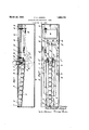
- FIG. 2 is a plan of one form of 50 Y device made in accordance with this invention
- the device comprises a rectangular casing a of sheet metal having a top b of cast aluminlum which is provided with a circular hole o near one end, a central opening d and a rectangular hole e at the other end.
- a tee f in the form of a short length of thin rubber tubing is carried on one end of a member or arm g which is pivoted at its other end on a pivot h supported in the casmg a., the tee f being adapted to project through the central opening d when in the raised position.
- the tee f secured by fixing with rubber solution to a spigot z' provided with a central hole through which the screw j passes and secures it in a cylindrical recess o; in the memberg.
- the member g is formed with a heel c at the extreme free end, the surface of the said heel being shaped as an arc about the pivot L.
- the member g is fur ther provided with a screw stop m adapted to co-act with the top b, an operating face n and a lug o through which is mounted a bolt p which projects below the member g and to the end of which is attached one end of the tension spring g.
- the other end lof the ten sion spring q is anchored to a bolt 1' fixed in the top b.
- the magazine for holding the balls comprises two L section girders s of aluminium supported at a slight incline on supports t and t provided on the top b.
- the girders .s axe spaced apart a short distance, the'lower ends of the girders being adjacent the heel k of the arm g which is adapted to pass between them and to pick up a ball therefrom on the tee f while the girders s are arranged to diverge slightly towards the lower end so as to provide suicient space for the passage of the tee f and member g but not sufficient to allow a ball to drop between them.
- Adjustable stops u are provided in the sup orts to limit the forward movement of the alls.
- the magazine is adapted to be filled through the circular hole o in the top b.
- the supports t are also adapted to serve as guides for the member g.
- the member g is preferably made a loose fit on the pivot h.
- the top ⁇ b is suitably stepped to receive a rubber mat lw secured in place by plates and screws y, the mat being provided with an opening corresponding to the central opening d to allow passage of the ball and tee.
- the mat w protects the top b from accidental damage and also prevents the club from being injured.
- the tee can be recharged by repeating this operation until the magazine is exhausted. If the dev-ice has been used in combination with a net, the player may then obtain practice in putting by putting the balls back into the circular hole c in the top b, thus recharging the magazine. If it is desired to alter the height of the tee, the adjustable screw stop m can be easily reached with a screw driver through the hole d in the top b. If the spring g is too strong, the balls may be bounced oli' the tee when the stop m comes in contact with the top b and if it is too weak, it may not be sufliciently strong to lift the ball and hold itin the uppermost position.
- the effect of the spring g can easily be adjusted through the hole e in the top b provided for the platform n when the member g is depressed.
- means may be provided fOr emptied perlodically adjusting the torque due to the counterwei ht.
- the surface of the heel k,'which makes contact with the end ball in the magazine, is formed as an arc about the pivot zso that its movement is not obstructed by the balls in the ma azine. This ensures that the movement o the memberv g is not hampered unduly by the balls .in the magazine.k
- any mud collected on the balls is able to fall through the gap into Athe bottom of the casing instead of clogging the magazine, and the casing may be or when necessary.
- the girders .s act as rails on which balls can roll freely but at the same time are kept strictly in line.
- An apparatus of the character described including a pvotally mounted member carrying a tee, means for yieldin 1y urging the end of said member carr 'ng te tee upward, and a magazine include ing inclined guide members whose lower ends straddle the free end of said pvotally mounted member.
- Apparatus for playing a game comprising a tee secured directly to a pivoted member adapted to be lowered and raised, means for supplying a ball to said tee when in lowered position comprising lateral guides disposed on each side of said pivoted member adjacent to said tee and means for continually urging said member to a normal raised position, the said tee being adapted to Vbe lowered by force supplied directly to said member by the player.
- Apparatus according to claim 2 in combination with means for limiting the movement of the tee in the upward direction, said means comprising means for limiting the movement of the pivoted member, said means being adjustable.
- Apparatus according to claim 2 the said tee being secured to an arm of a pivoted member and the said means for urging the tee to the normal raised position comprising a spring operably connected to the said pivoted member.
- Apparatus for playing a game comprising a tee secured directly to a pivoted member adapted to be lowered and raised, means for supplying a. ball to said tee when in lowered position and means for continually urging said member to a normal raised position, the said tee being adapted to be lowered by force supplied directly to said member by the player, ball supply means comprising a magazine from Which the balls are fed by gravity, the tee end of the said pivoted member being shaped as an arc described about the pivot about which the said arm moves, the end of the said arm acting as a stop to restrain the feed of the balls whilst the tee is in its raised position.
- 2 FELIX ALEXANDER JOSEPH.
Landscapes
- Health & Medical Sciences (AREA)
- General Health & Medical Sciences (AREA)
- Physical Education & Sports Medicine (AREA)
- Pinball Game Machines (AREA)
Description
F. A. JOSEPH APPARATUS FOR PRACTICING GAMES March 22, 1932.
Filed F'eb. 15 1929 Patented Mar. 22. 1932 FELIX ALEXANDER JOSEPH.; F HEIPSTEAD, LONDON, ENGLAND APPARATUS FOB PRAGTICING GMES 'Application mea rebruaxy 1s, 192s, semi 1ro.' 340,089, ma in amt mitm' my as, um.
This invention `relates to apparatus for practicing games and for playmg games 1n which a ball is adapted to be struck from a tee by the player using a club or other appli- 5 ance, and relates more particularly to apparatus comprising a mechanical tee.
The ob]ect of the lpresent invention is to provide improved apparatus to enable the player to practice the-game more conveniently or otherwise to amuse himself.
Apparatus made in accordance with this invention comprises a tee oi which a ball is to beA struck, said tee being adapted to be lowered and raised, means for supplying a l5 ball'to the tee in the lowered position and means comprising a spring or counterweight for continually urging `the said tee to the normal raised position, the said tee being arranged to be lowered by force supplied by the player.
The invention further consists in constructing the said tee in the form of a resilient tube, and the lower end of the said tube maybe secured by fixing with cement or rubber solution to the outside of a cylindrical spigot preferably of hard rubber adapted to be secured to a movable member of the apparatus, and the said movable member may be mounted on a pivot and provided with an .3 arm to the extremity of which the tee is secured.
The invention further consists in providing guides for the pivoted member and means for adjusting the limits of movement of the said pivoted member.
An improved magazine is also provided which is designed to assist in clearing the magazine of any dirt which may be introduced with the balls.
In one construction the top of the apparatus is provided with a circular hole which communicates with the magazine so that the balls, after having been driven o, may be putted back into the hole, thus giving practice at putting aswell as serving to replenish the magazine. 4
elevation and'Fig. 2 is a plan of one form of 50 Y device made in accordance with this invention The device comprises a rectangular casing a of sheet metal having a top b of cast aluminlum which is provided with a circular hole o near one end, a central opening d and a rectangular hole e at the other end.
A tee f in the form of a short length of thin rubber tubing is carried on one end of a member or arm g which is pivoted at its other end on a pivot h supported in the casmg a., the tee f being adapted to project through the central opening d when in the raised position. The tee f secured by fixing with rubber solution to a spigot z' provided with a central hole through which the screw j passes and secures it in a cylindrical recess o; in the memberg. The member g is formed with a heel c at the extreme free end, the surface of the said heel being shaped as an arc about the pivot L. The member g is fur ther provided with a screw stop m adapted to co-act with the top b, an operating face n and a lug o through which is mounted a bolt p which projects below the member g and to the end of which is attached one end of the tension spring g. The other end lof the ten sion spring q is anchored to a bolt 1' fixed in the top b. By screwing the bolt p in the lugV 0 the leverage about the pivot h canbe varied and this construction provides delicate adjustment of the effect of the tension spring g on the arm g. The downward movement of the member g is limited by the heel lc coming into contact with the bottom of the casing a but any other form of stop may be provided.
The magazine for holding the balls comprises two L section girders s of aluminium supported at a slight incline on supports t and t provided on the top b. The girders .s axe spaced apart a short distance, the'lower ends of the girders being adjacent the heel k of the arm g which is adapted to pass between them and to pick up a ball therefrom on the tee f while the girders s are arranged to diverge slightly towards the lower end so as to provide suicient space for the passage of the tee f and member g but not sufficient to allow a ball to drop between them. Adjustable stops u are provided in the sup orts to limit the forward movement of the alls. lVhen the member g is depressed the balls will move forward until the first ball is against the stops u in the osition for being picked up by the tee f in lts upward movement between the lower end of the girders. The magazine is adapted to be filled through the circular hole o in the top b. y
The supports t are also adapted to serve as guides for the member g. The member g is preferably made a loose fit on the pivot h.
The top `b is suitably stepped to receive a rubber mat lw secured in place by plates and screws y, the mat being provided with an opening corresponding to the central opening d to allow passage of the ball and tee. The mat w protects the top b from accidental damage and also prevents the club from being injured.
In operation, assuming that the empty tee is in its uppermost position and the magazine is loaded, the player depresses the member .g by pressing on the operating face n with his club and holds it down momentarily in its lowest position.` As soon as the tee f is below the girders s the lowest ball in the magazine which has been restrained by the heel k, moves forward against the stops u. On the play-er removing his club from the face n the spring g raises the member g 1n its upward movement, the tee f collects the said ball from the magazine and raises it through the hole in the top b in position ready for the player to strike. After playing a ball, the
tee can be recharged by repeating this operation until the magazine is exhausted. If the dev-ice has been used in combination with a net, the player may then obtain practice in putting by putting the balls back into the circular hole c in the top b, thus recharging the magazine. If it is desired to alter the height of the tee, the adjustable screw stop m can be easily reached with a screw driver through the hole d in the top b. If the spring g is too strong, the balls may be bounced oli' the tee when the stop m comes in contact with the top b and if it is too weak, it may not be sufliciently strong to lift the ball and hold itin the uppermost position. The effect of the spring g can easily be adjusted through the hole e in the top b provided for the platform n when the member g is depressed. Similarly, if a counterweight instead of a spring is used, means may be provided fOr emptied perlodically adjusting the torque due to the counterwei ht.
T e end of the arm g adjacent the heel as well as the tee f itself to ether .serve as a stop to restrain the forwar movement of the balls until the tee f is lowered sullciently to receive i. ball. The surface of the heel k,'which makes contact with the end ball in the magazine, is formed as an arc about the pivot zso that its movement is not obstructed by the balls in the ma azine. This ensures that the movement o the memberv g is not hampered unduly by the balls .in the magazine.k
By forming the floor of the magazine of two girders s spaced apart, any mud collected on the balls is able to fall through the gap into Athe bottom of the casing instead of clogging the magazine, and the casing may be or when necessary. Furthermore, the girders .s act as rails on which balls can roll freely but at the same time are kept strictly in line.
What I claim and desire to secure by Letters Patent is: f
1. An apparatus of the character described including a pvotally mounted member carrying a tee, means for yieldin 1y urging the end of said member carr 'ng te tee upward, and a magazine inclu ing inclined guide members whose lower ends straddle the free end of said pvotally mounted member.
2. Apparatus for playing a game, comprising a tee secured directly to a pivoted member adapted to be lowered and raised, means for supplying a ball to said tee when in lowered position comprising lateral guides disposed on each side of said pivoted member adjacent to said tee and means for continually urging said member to a normal raised position, the said tee being adapted to Vbe lowered by force supplied directly to said member by the player.
3. Apparatus according to claim 2 characterized by the fact that the guides are disposed just clear of the normal path of said pivoted member.
4. Apparatus according to claim 2 in combination with means for limiting the movement of the tee in the upward direction, said means comprising means for limiting the movement of the pivoted member, said means being adjustable.
5. Apparatus according to claim 2, the said tee being secured to an arm of a pivoted member and the said means for urging the tee to the normal raised position comprising a spring operably connected to the said pivoted member. i
6. Apparatus according to claim 2., the said ber, through a member of adjustable length for varying the strength of the spring.
7. Apparatus for playing a game comprising a tee secured directly to a pivoted member adapted to be lowered and raised, means for supplying a. ball to said tee when in lowered position and means for continually urging said member to a normal raised position, the said tee being adapted to be lowered by force supplied directly to said member by the player, ball supply means comprising a magazine from Which the balls are fed by gravity, the tee end of the said pivoted member being shaped as an arc described about the pivot about which the said arm moves, the end of the said arm acting as a stop to restrain the feed of the balls whilst the tee is in its raised position. 2 FELIX ALEXANDER JOSEPH.
Applications Claiming Priority (1)
| Application Number | Priority Date | Filing Date | Title |
|---|---|---|---|
| GB1850174X | 1928-05-23 |
Publications (1)
| Publication Number | Publication Date |
|---|---|
| US1850174A true US1850174A (en) | 1932-03-22 |
Family
ID=10891933
Family Applications (1)
| Application Number | Title | Priority Date | Filing Date |
|---|---|---|---|
| US340089A Expired - Lifetime US1850174A (en) | 1928-05-23 | 1929-02-15 | Apparatus for practicing games |
Country Status (1)
| Country | Link |
|---|---|
| US (1) | US1850174A (en) |
Cited By (4)
| Publication number | Priority date | Publication date | Assignee | Title |
|---|---|---|---|---|
| US4602789A (en) * | 1983-05-06 | 1986-07-29 | Chung Bong J | Golf ball teeing apparatus |
| US5611737A (en) * | 1995-06-28 | 1997-03-18 | Rau; Timothy P. | Golf training device |
| WO2003004110A1 (en) * | 2001-07-03 | 2003-01-16 | Snuk Limited | Mechanical handling device for golf balls at a driving range |
| US20030162598A1 (en) * | 2000-07-26 | 2003-08-28 | Eckardt Jr Franz Charles | Golf ball teeing device |
-
1929
- 1929-02-15 US US340089A patent/US1850174A/en not_active Expired - Lifetime
Cited By (10)
| Publication number | Priority date | Publication date | Assignee | Title |
|---|---|---|---|---|
| US4602789A (en) * | 1983-05-06 | 1986-07-29 | Chung Bong J | Golf ball teeing apparatus |
| US5611737A (en) * | 1995-06-28 | 1997-03-18 | Rau; Timothy P. | Golf training device |
| US20030162598A1 (en) * | 2000-07-26 | 2003-08-28 | Eckardt Jr Franz Charles | Golf ball teeing device |
| US20040224782A1 (en) * | 2000-07-26 | 2004-11-11 | Tee Up Pty Ltd. | Golf ball teeing device |
| US20050020370A1 (en) * | 2000-07-26 | 2005-01-27 | Tee Up Pty Ltd. | Golf ball teeing device |
| US7059969B2 (en) | 2000-07-26 | 2006-06-13 | Tee Up Pty Ltd. | Golf ball teeing device |
| US7104421B2 (en) | 2000-07-26 | 2006-09-12 | Tee Up Pty Ltd. | Golf ball teeing device |
| WO2003004110A1 (en) * | 2001-07-03 | 2003-01-16 | Snuk Limited | Mechanical handling device for golf balls at a driving range |
| US20040082398A1 (en) * | 2001-07-03 | 2004-04-29 | Philip Gager | Mechanical handling device for golf balls at a driving range |
| US6997816B2 (en) | 2001-07-03 | 2006-02-14 | All Year Ventures Ltd | Mechanical handling device for golf balls at a driving range |
Similar Documents
| Publication | Publication Date | Title |
|---|---|---|
| US2939705A (en) | Basketball practice device | |
| US4265453A (en) | Automatic golf teeing devices | |
| US2071356A (en) | Method for teeing golf balls and device therefor | |
| US1850174A (en) | Apparatus for practicing games | |
| US2450206A (en) | Golf teeing apparatus | |
| US2212877A (en) | Golf teeing device | |
| US1449012A (en) | Automatic pin-spotting mechanism | |
| US1776161A (en) | Ejecting device | |
| KR101949433B1 (en) | Ball supplying system and control method for the same | |
| US2348540A (en) | Automatic bowling alley | |
| EP0002921B1 (en) | Improvements in automatic golf teeing devices | |
| US2448951A (en) | Toy bank | |
| US1681590A (en) | Bowling game board | |
| US1692191A (en) | Golf tee | |
| US1255140A (en) | Adjustable golf-ball-tee device. | |
| US2626154A (en) | Pin spotter for miniature bowling games | |
| US20080234061A1 (en) | Golf ball teeing system | |
| US1972894A (en) | Automatic golf tee | |
| US460025A (en) | Bowling-alley | |
| US2653815A (en) | Golf putting practice device | |
| CN110201355B (en) | Interesting pulling force exercise device | |
| US2464550A (en) | Automatic tee | |
| US1923682A (en) | Golf tee | |
| US1836640A (en) | Toy | |
| US598894A (en) | Island |