US1850149A - Heel-seat fitting machine - Google Patents
Heel-seat fitting machine Download PDFInfo
- Publication number
- US1850149A US1850149A US444559A US44455930A US1850149A US 1850149 A US1850149 A US 1850149A US 444559 A US444559 A US 444559A US 44455930 A US44455930 A US 44455930A US 1850149 A US1850149 A US 1850149A
- Authority
- US
- United States
- Prior art keywords
- heel
- shoe
- sole
- machine
- breast
- Prior art date
- Legal status (The legal status is an assumption and is not a legal conclusion. Google has not performed a legal analysis and makes no representation as to the accuracy of the status listed.)
- Expired - Lifetime
Links
Images

Classifications
-
- A—HUMAN NECESSITIES
- A43—FOOTWEAR
- A43D—MACHINES, TOOLS, EQUIPMENT OR METHODS FOR MANUFACTURING OR REPAIRING FOOTWEAR
- A43D8/00—Machines for cutting, ornamenting, marking or otherwise working up shoe part blanks
- A43D8/32—Working on edges or margins
- A43D8/34—Working on edges or margins by skiving
-
- A—HUMAN NECESSITIES
- A43—FOOTWEAR
- A43D—MACHINES, TOOLS, EQUIPMENT OR METHODS FOR MANUFACTURING OR REPAIRING FOOTWEAR
- A43D8/00—Machines for cutting, ornamenting, marking or otherwise working up shoe part blanks
- A43D8/46—Splitting
- A43D8/48—Splitting combined with skiving
Definitions
- Thi invention relates to the manufacture of shoes and is herein illustrated as embodied in a machine'by means of which the heeh seat portions of the soles of shoes may be trimmed prior to the attachment of heels to the shoes.
- 1,840,030 arearranged to move substantially at right angles to the median line of the sole to operate upon shoes to which Cuban heels areto be'attached while the shoulderingfknives disclosed in application' Serial No. 349,443 are mounted for movement toward and awayfrom each other breast corners of which have 'beentruncated to provide shoulders complemental to the.
- heel-breast-receiving shoulders and constructed and arranged to engage the heelbreast-rccoiving shoulders in the finished shoe.
- the illustrated machine comprises plates or fingers constructed and arranged to enter the rand crease of a shoe at opposite sides of and in the vicinity of the breast line of the Isoleof the shoe, and cutters mounted for movement relatively to the shoe and .constructed and arranged for cooperation with the fingers to provide shear couples for forming h'eel-breast-receiving shoulders upon the sole.
- each of the shoulder-forming cutters andthe finger with which it cooperates are mounted for movement about an axis at rightangles to the sole of the shoe bein operated upon for forming heel-breastreceivi-ng shoulders inclined at different angles to the lengthwise median lineofthe sole.
- the fingers havetheir shear edges constructed and arranged to contact with the shoulderforming knives to prevent these knives from springing during the entire shoulder-forming operation and also support the sole at the breast line thereof and prevent the shoe upperfrom getting into the path of the beveling knives which are moved lengthwise of the sole to reduce the heel-seat portion of the sole above mentioned.
- the heel being centrali'zedin the heel "gage by members which engage the sides of the heel and being moved against the breast by a slide suitably shaped for engaging the rear portion of the heel andconnected to the back gage.
- the illustrated machine is provided with a novel gage for determining the lengthwise position of a shoe in the machine, and a gage constructed and arranged to receive a heel and to control the position of the shoe-positioning gage.
- this heel-receiving gage has abutments mounted for movement toward and away from each other and constructed and arranged for engaging the rear and of the heel.
- breast gage members comprising an abutment for engaging the central portion of the breast of 21- Louis heel and another abutment mounted for movement relatively to the first-mentioned abutment into and out of operative position, and shaped and rranged to engage the corner portions of the breast of a Cuban heel. ll hen this Cuban heel abutment is in its operative posi tion, it renders the abutment used in Louis work ineiiective.
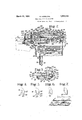
- Fig. 1 is a plan View illustrating an improved heel-seat fitting machine, parts of which have been omitted and other parts of which have been broken away clearly to show the construction of the machine;
- Fig. 2 shows a vertical section of the machine taken along a longitudinal median portion thereof
- Fig. 3 is an enlarged front view of a portion of the machine for forming heel-breastreceivin shouldersinclined at different angles to the median line of the sole of the shoe being operated'upon in the machine;
- Fi s. 4 and 5. are illustrative views showing tie relative positions of a crease plate of the improved machine and a correspond ing finger which enters the rand crease of the shoe being operated upon in the vicinity of the heel-breast line of the sole of the shoe, and which cooperates with a knife or cutter movable widthwise of the shoe to form a heel-breast-receiving shoulder on the sole;-
- Figs. 6 and 7 show an alternative construction of crease plate and finger which may be used in place of the construction illustrated in Figs. 4 and 5; and l y Fig. 8 is a perspective view illustrating the relative positions ofthe lingers and the knives which cooperate therewith to form heel-breast-receiving shoulders on the sole.
- the illustrated machine is of the type disclosed in the aboVe-referred-to application for Letters Patent Serial No. M9343, which may be consulted for a better understanding of such features not hereinafter described.
- the illustrated machine as fully set forth in such application, comprises a shoe support 10 movable toward and away from the trimming portiongof the machine in a guideway 12 in the forwardly extending portion 14 of the machine frame and upon which portion ashoe (Fig. 2) having a sole attache'd thereto is mountedbottom side up and heel end away from theoperator, and a pair of sliding beds 16 positionedvat opposite sides of the machine and movable toward and away from each other in guideways 18 of the frame.
- Each of the sliding beds has a crease plate 20 attached thereto at its forward inner portion and is provided with a raised overhanging portion 22 having a dove-tailguide 2a in which the arms 21 carrying beveling knives 26 for trimming the heel-seat portion. of a shoe positioned in the machinev lengthwise thereof to reduce the heel-seat portion thereof are mounted for reciprocation lengthwise of the shoe.
- Each of the beveling knives 26 is inclined at an angle to'the sole of the shoe upon the support 10 and the lower outer corners 28 of the knives engage within recess portions 30 of the crease plates 20.
- the illustrated machine is specially adapted for operating upon a short sole, the rear part of the heel-seat portion of which has been previously trimmed and that the sole being operated upon is substantially undistorted when positioned in the machine since the entering portions 32 of the crease plates 20' are sufiicientlynarrow to. enter the rand crease without curling up the lateral margins of the heeleseat portion of the sole, and the beveling knives 26 which are inclined to the plane of the undistorted sole serve to trim the lateral marginal portions of the sole at the desired bevel for fitting within the attaching face of applied to the shoe.
- the shoe In order to perform the trimming operation, the shoe is placed upon the support 10 which is moved rearwardly of the machine until the rear portion of the counter of the shoe upperengages a back. gage 34, the con struction and operation of which will be described later.
- the sliding beds 16 are moved toward each other by moving clownwardly a vertically disposed rod 36 pivotally connected to links 38, which are hinged to the under sides of the sliding beds and are described in detail in the above-mentioned applications, until the crease plates 20 enter the rand crease of the'shoe and engage the line of sole-attaching stitches which extend for a short distance rearwardly of the heelbreast line of the sole.
- yThe sliding beds 16 are normally urged apart by a spring 35 (Fig. 2), the upper part of which is attached to the frame and the lower part of which is attached to the rod 36.
- the machine disclosed in application Serial No. 349,443 is especially suited for operating upon Louis heel work and as above stated comprises a pair of beveling knives 26 in clined to the plane of the sole and constructed and arranged to enter the rear portion of the sole and to move forwardly thereof to reduce the heel-seat portion of the sole.
- a pair of beveling knives 26 in clined to the plane of the sole and constructed and arranged to enter the rear portion of the sole and to move forwardly thereof to reduce the heel-seat portion of the sole.
- the heel-breast line knives 45-but carried on guides and mounted for reciprocation in guideways in the sliding beds at the forward portions thereof, the guides being movable in rectilinear paths extending forwardly of the shoe as they approach the shoe at a constant angle relatively to'the median line of the sole of the shoe.
- Each of the sliding beds is extended forwardly of the machine and the forward portion 46 thereofis provided with a laterally extending horizontal guideway 48 which extends from near the inner margin of the sliding bed 16 to its outer margin at an angle of about 12 degrees to the direct-ion of movement of the beveling knives 26.
- a sliding block 50 to which is affixed a vertical rod 52 extending downwardly therefrom and adjustable relatively to the sliding block 50 in a recess 54, the lower portion of the rod 52 being embraced by the bifurcated portion 56 of a forwardly and rearwardly extending arm 58 pivoted to the sliding bed 16 at 60.
- the mechanism by which the arm 58 is operated will be described later.
- a plate 62 Integral with and attached to the sliding block 50 is a plate 62 having in its upper face an arcuate recess 64.
- a guide 66 mounted upon the top of the sliding bed 16 above the plate 62 and extending laterally of the machine is a guide 66 constructed and arranged to support and to control the path of movement of the knives 45 which are constructed and arranged to form heel-breast-receiving shoulders on the sole, the guide 66 being fixed in adjusted position by two clamping bolts 68, 70.
- the bolt ill 68 passes through an arcuate slot 72 near the inner margin of the sliding bed 16 and has a flanged head 74 for engaging the lower surface of the sliding bed 16, whereby the bolt 68 upon being turned will lock the guide 66 to the sliding bed 16 orwill release the guide for adjusting it relatively to the sliding bed.
- the bolt has a flange 7 6 at its lower portion for engaging the lower surface of the outer lateral portion of the sliding bed 16, the upper portion of the bolt 70 passing through the guide 66 and having a threaded upper portion which has a nut 78 screwed therein to draw the flange 7 6 against the sliding bed 16 or to lower the flan e 7 6 away from the sliding bed.
- the guide is thus mounted for adjustment in a horizontal plane about a vertical axis or virtual pivot 80 which passes through a point which is approximately the most forward point reached by the outer lower corner 28 of the adjacent beveling knife 26 during its cutting stroke. This point will vary according to the position laterally of the machine of the sliding bed,
- the upper portion of the guide 66 is provided with extending flanges 84 forming a T- shaped guide upon which is mounted a knifecarrying slide 86 having a concavity at its lower surface complementary to the T-shaped portion of the guide. It will thus be clear that the knife-carrying slide 86 is adjustable together with the guide 66 about the virtual pivot 80 aforementioned, which pivot extends substantially at right angles to the sole of the shoe being operated upon in the machine.
- the lmifecarrying slide 86 is provided with a vertical pin 88 extending downwardly from the slide through a slot 90 in the guide 66 and carrying upon its lower end an anti-friction roll 92 which fits into the arcuate recess 64 in the plate 62.
- the shouldering knife 45 is mounted as follows.
- the inner end of the knife-carry ing slide 86 carries an upstanding flange 94,
- the inner face 96 of which is provided with an arcuate slot 98 adapted to receive a corresponding tongue 100 on the outer face of a segmental wing 102 from the front margin of which there is an extension 104 provided with a recess 106 in which is positioned the shouldering knife 45 secured to and adjustable relatively to the extension 104 of the segmental wing 102 by a screw-and-slot arrangement 108.
- the plane of the shouldering knives may be adjusted about a horizontally disposed axis extending widthwise of the positioned shoe, the segmental wing 102 being clamped to the upstanding portion of the knife carrier by a screw 110 which passes through an arcuate opening 112 in the upstanding flange 94.
- the guide is adjusted into what is substantially its rearmost position with the result that on the operation of the machine the knife 45 will move inwardly and forwardly of the shoe at an angle of about 75 degrees with the median line of the shoe to form heel-breast-receiving shoulders upon the sole. If Cuban work is being operated upon, however, the guide is adjusted forwardly to an extent determined by the shape of the breast of the heel which is to be attached to the sole so as to out upon the sole a shoulder which is often substantially at right angles to the median line of the sole or which may extend rearwardly of the shoe as it approaches the median line of the sole.
- the shouldering knife in whatever position of adjustment it may be, passes during its cutting movement along and in contact with the front face 120 of the plate or finger 114 which enters the rand crease of the shoe in the vicinity of the breast line thereof and which acts to protect the shoe from the beveling and shouldering knives and cooperates with the knife to form a shearing couple.
- the knife 45 may be slightly sprung against the front face 120 of the finger 114, and in order to provide a shear edge 122 (Fig. 8) with which the knife 45 effectively cooperates to. form heelbreast-receiving shoulders inclined at different angles to: the: planeof the sole, the frontface 120 of the finger? 114 may be1slightly undercut as illustrated.
- a link 1.48 is pivoted near one of its ends to the lock 144 and its other end is pivoted to a laterally extending arm 150 of a sleeve w which is carried by and pivoted to the under part of one of the sliding beds'16 at and which comprises the arm 58 above described.
- the back gage 34 with which the rear portion of the shoe upper engages as above described, the back gage being slidable forwardly and rearwardly of the machine in a guideway 162 and being positioned through mechanism which will now be described.
- the top portion of the machine carries a heel-receiving gage 164 and connectingmechanism for regulating the position of the back gage to which is attached an upwardly extending post166' (Fig. 2) connected at its.
- a traveler 168 slidable forwardly and rearwardly of the machine in a guideway 170.
- An upstanding member 172 is connected tothe traveler 168 and is provided with a threaded recess 17 4 extending parallel to the guideway 170 and is constructed to receive a screw 176- having a knurled head 178 at its rear end. 1
- the front end of the screw 176 is provided witha collar 180 that lies in a recess 182 (Fig. 1) in a rear abutment 184 which has a curved recessed forward portion 186 for receiving the rear marginal rim portion of a heel in'the heel-receiving gage 164.
- the front portion of the top of the machine carries a gage member 188 havingan abutment 189 arranged to engage the breast of the projecting lip of a Louis heel, the gage member 188 being mounted for forward and rearward adjustment in a guideway 190 in order to accommodate different sizes of heels,
- a clamping member or abut- 1 ment 202 screwed thereto a clamping member or abut- 1 ment 202, the heel contacting end 204 of which is inclined forwardly and toward the other clamp at an angle of about 7 5 degrees to the horizontal and preferably carries a clamp piece of rubber or leather in order that the clamp will not damage the covering of the heel.
- pivot pins 206 Projecting downwardly from the clamp slides 198 are pivot pins 206 connected by links 208 to other pivot pins 210 which proupper surface of the heel clamp actuator 212 3 the heel are trimmed to form shoulders thereare provided with racks 214, 216 respectively, which engage a pinion 218 carried by a compensating block 220 slidable in a guideway 222 in the top portion of the frame of the machine.
- the compensating block 220 is operated by a pin 224 extending from one side thereof and arranged to be received by a bifurcated portion 226 of an upwardly extending arm 228 fixed upon a rock shaft 230 mounted for oscillation in a bearing 232 of the machine frame.
- the clamp members 202 are mounted for movementwith the rear abutment 184 through the pinion 218 carried by the compensating block 220 and are arranged to engage the heel, laterally to position the same widthwise thereof in the machine before the heel is positioned lengthwise thereof in the machine.
- the rear abutment 184 is arranged to engage the heel and to move the same against the gage member 188.
- the rear abutment 184 and the clamping members or abutments 202 are normally urged toward the heel and are locked in their foremost positions, as clearly disclosed in application Serial No. 349,443 through a spring 236 attached to an arm 238 which through the rock shaft 230 normally urges the upwardly extending arm 228 forwardly of the machine carrying with it the compensating block 220 which through the mechanism above described urges the rear abutment 228 forward ly of the machine and the clamping members or abutments 202 toward each other.
- rear abutment 184 and the clamping members or abutments 202 may be moved away from each other by swinging the rock shaft in the direction indicated by arrow 231 through the arm 238 or any other suitable mechanism controlled by the operator.
- a Cuban heel usually has a concave breast and in view of the fact that the con cavities in the breasts of heels of the same size and style may vary, it is preferable to locate a Cuban heel in the heel gage by a gage member which contacts with the marginal portions of the breast of a heel rather than with the middle portion of the breast of the heel.
- a gage member which contacts with the marginal portions of the breast of a heel rather than with the middle portion of the breast of the heel.
- applicants machine is equipped with the gage member 188 having the abutment 189 constructed and arranged to contact with the middle portion of the lip of a Louis heel and having another abutment 240 for engaging the lateral marginal portions of the breast of a Cuban heel.
- a Cuban heel is normally considerably shorter than a Louis heel, it is convenient, in order to save adjustment of the gage member when changing from one type of work to the other that the gaging face 242 of the abutment 240 for engaging a Cuban heel should be located rearwardly of the position of the gaging face 244 of the abutment for a Louis heel by an amount approximatelyequal to the diiference in length between a normal Louis heel and a normal Cuban heel of the medium size.
- the gage member 188 is provided with two up standing lugs 246 between which extends a horizontal transversely extending pivot pin 248 upon which is mounted the abutment 240 designed for Cuban heel work and comprising a bifurcated portion 252 that embraces and extends rearwardly of the abutment 189.
- the gaging face 242 of the abutment 240 for Cuban heel work is provided with laterally extending surfaces which extend slightly forward from their base portions upwardly and which are constructed and arranged to engage lateral portions of the breast of a Cuban heel.
- the lateral portions of the abutment for Cuban heel work are extended outwardly into such position that should the abutmentbe swung over rearwardly about its pivot pin 248 the abutment 240 will strike the heel-trimming knives 234, and will therefore be unable to move down to its operative position until the trimming knives 234 have been removed from the machine.
- the abutment 240 is swung upwardly about its pivot pin into an inoperative position so as not to interfere with use of the abutment 189.
- a back gage 84 is first adjusted properly to position a shoe lengthwise thereof in the machine. This is effected by positioning a heel to be attached to the shoe or one similar to it'in the heel-receiving gage 164., the lengthwiseposition of the heel in the gage being determinedby the abutment 240 when operating on Cuban heel work or by the abutment 189 when operating on Louis heel work, and the'rear abutment 184i and the clamping members 202 being retr cted for allowing the heel tobe inserted in the heelreceiving gage 16 lby depressionof the arm 238 which swings the rock shaft 230 in a di rection indicated by reference numeral 231.
- the spring 236, through mechanism above described, moves the rear abutment 184 and the clamping members 20 against the heel so that the breast of the heel engages the gage member 188. relatively to the median line of the sole of the shoe to be presented to the machineis next determined, the guide 66 being adjustable by bolts 68, 70 for controlling the path of move ment of the knives 45 widthwise of the shoe.
- the shoe to which the sole is attached is placed upon the support 10 bottom side up and heel end away from the operator, who pushes the support rearwardly in the guideway 12 he moves the rod 36 down by a suitable treadle (not shown) in ordertomove the sliding beds toward each other, the crease plates 20 entering the rand crease of the shoe at opposite sides thereof as the shoe is moved rearwardly of the machine upon the support;
- the crease plates 20 continue to enter the rand crease until their inner edges 12 engage the lines of sole-attaching stitches which extend rear wardly of the breast, line of the sole.
- the clamp or sole holddown 40 is. then moved downwardly against the attaching face of the sole and assists in retaining the shoe in position in the machine.”
- a one-revolution clutch (not shown) is actuated to rotate the drive shaft 1.34 which operates in succession the beveling knives 26 and the shouldering knives lfj as well as the knives 234 which move toward each other for truncating the upper breast corners of a Louis heel when the machine is operating upon Louis heel work.
- a heel-seat fitting machine having, in combination, fingers mounted for simultaneous movement widthwise of a shoe positioned in the machine and constructed and arranged to enter the rand crease of the shoe at opposite sides of the shoe and in the vicinity of the breast line of the sole of the shoe, and cutters mounted for movement relatively to the shoe and constructed and arrangedto-cooperate with said fingers to provide shear couples for forming heel-breast-receiving shoulders upon the sole, said fingers and said cutters being adj ustable about aXes arranged substantially at right angles to the sole to vary the angle at which the heel-breast-receiving shoulders are inclined to the lengthwise medium line of the sole.
- a heal-seat fitting machine having, in combination, means for positioning a shoe, cutting means for reducing the heel-seat portion of the sole of the shoe, cutters mounted for movementwidthwise of the sole of the shoe and adjustable about aXes arranged substantially at right angles to the sole to vary the direction of movement of the cutters widthwise of the sole thereby forming heelthe rand or r the shoe at opposite sides of the shoe and in the vicinity of the breast line of the sole for supporting the sole and for holding the shoe upper out of the path of said cutters and said cutting means during the heel-seat fitting operation.
- a heel-seat fitting machine having, in combination, crease plates for engaging within the rand crease of the rear portion of a shoe, fingers mounted for movement relatively to said crease plates and constructed and arranged to engage within the rand crease of a shoe at opposite sides of the shoe and in the vicinity of the breast line of the sole of the shoe, and cutters mounted for movement widthwise of the sole and constructed and arranged to cooperate with said fingers to provide shear couples for forming heel-breast-receiving shoulders upon the sole.
- A. heel-seat fitting machine having, in combination, means for positioning a shoe, cutting means for reducing the heel-seat portion of the sole of the shoe, cutters mounted for movement vidthwise of the sole of the shoe and adjustable about axes arranged substantially at right angles to the sole to vary the direction of movement of the cutters widthwise of the sole thereby forming heelbreast-receiving shoulders inclined at different angles to the median line of the sole, plates mounted for adjustment about said axes and constructed and arranged to enter the rand crease of the shoe at opposite sides of the shoe and in the vicinity of the breast line or" the sole for supporting the sole and for holding the shoe upper out of the path of said cutters and said cutting means during the heel-seat fitting operation, and means for ad usting the knives about axes parallel to the sole to vary the angle which the heelcouples for forming heel-breast-receiving shoulders upon the sole, said plates and said cutters being adjustable about axes arranged substantially at right angles to the sole of the shoe for
- a heel-seat fitting machine having, in combination, means for positioning a shoe, a pair of guides positioned at opposite sides of the shoe and mounted for adjustment about axes substantially normal to the sole of the shoe, a pair of cutters mounted for movement upon said guides, and fingers mounted for movement with the guides about said axes and arranged to enter the rand crease of the shoe in the vicinity of the breast line of the sole of the shoe and to form with the cutters shear couples for cutting heel-breast-recciving shoulders upon the sole.
- a heel-seat fitting machine having, in combination, means for positioning a shoe, cutters mounted for movement to reduce the heel-seat portion of the sole of the shoe, a pair of guides mounted for adjustment about axes substantially normal to the sole of the shoe, cutters mounted for movement upon said guides and constructed and arranged to form heel-breast-receiving shoulders upon the sole, and a pair of fingers mounted for movement with the guides about said axes and constructed and arranged to enter the rand crease of the shoe in the vicinity of the breast line of the sole of the shoe for supporting the sole and holding the shoe upper out of the path of the cutters during the heel-seat fitting operation.
- a heel-seat fitting machine having, in
- a heel-seat fitting machine having, in combination, means for positioning a shoe having a sole attached thereto, a pair of guides positioned at opposite sides of the shoe and mounted for movement substantially widthwise of a shoe positioned in the machine and also mounted for adjustment about axes substantially normal to the sole of the shoe, a pair of fingers mounted for movement with the guides and constructed and arranged to enter the rand crease of the shoe in the vicinity of the breast line of the shoe, and knives mounted for movement upon said guides for forming heel-breastreceiving shoulders upon the sole.
- a heel-seat fitting machine having, in combination, a shoe support, crease plates constructed and arranged to enter the rand crease of a shoe upon the support, knives mounted for movement lengthwise of the shoe and having cutting edges inclined to the plane of the sole of the shoe for trimlid ming the lateral marginal portions of the heel-seat portion of the sole while the heelseat portion of the sole is substantially undistorted, and cutters for forming upon the substantially undistorted sole heel-breast-receiving shoulders inclined at different angles to the median line of the sole.
- a heel-seat fitting machine having, in combination, means for positioning a shoe having a sole attached thereto, means for reducing the heel-seat portion of the sole widthwise thereof while the heel-seat portion of the sole is undistorted, cutters, and means movable with and relatively to each of the cutters and constructed and arranged to cooperate witheach of the cutters to sever the sole thereby forming heel-breast-receiving shoulders inclined at different angles to the median line of the sole.
- a heel-seat fitting machine having, in combination, means for supporting a shoe having a sole attached thereto, means including sliding beds mounted for movement toward and away from the shoe-supporting means to cooperate with the same for positioning the shoe in the machine and for retaining the shoe in said osition, a knife movable with each of the Siding beds and mounted for movement relatively to the sliding bed in a direction lengthwise of the shoe to bevel the lateral marginal portions of the sole lengthwise thereof, and a knife mounted for angular adjustment relatively to the sliding bed and mounted for movement transversely of the sole to form upon the sole heel-breast-receiving shoulders inclined at different angles to the median line of the sole.
- a heel-seat fitting machine having, in combination, shoe-positioning means comprising a pair of plates constructed and arranged to enter the rand crease of a shoe and mounted formovement'towa'rd and away from each other,*a pair of fingers constructed and arranged to enter the rand crease of the shoe in the vicinity of the breast line of the sole and movable with saidplates, and apair of cutters mounted for movement widthwise 0f the sole and constructed and-arranged to cooperate with the fingers to shear portions ofthe sole for forming heel-'breast-receiving shoulders thereon, said cutters and'said fingers being mounted for adjustment about axes substantially normal :to the plane of the sole for varying the direction of movement of the cutters widthwise of the sole.
- a heel-seat fitting machine having, -in combination, means for positioning a shoe in the machine and comprising a gage con structed and arranged to 'receivea heel similarlto that to be attached to the shoe being operated uponand including a breast gage having an abutment for engaging a central portion of the breast of a heel in 'thegage, an abutment movable relatively to the firstand means for positioning and clamping the heel against the breast gage.
- a heel-seat fitting machine having, in
- means for determining the position of a shoe lengthwise thereof in the machine comprising a gage positioned against movement and having an abutment constructed and arranged to engage the central portion of the breast of a Louis heel, and having another abutment mounted for movement relatively to the first-named abutment and constructed and arranged when in operating positionto engage the lateral edges of the breast of a Cuban heel and to render the first-named abutment ineffective, and means for positioning a heel and clamping it against one of the abutments.
- a heel-seat fitting machine having,'in combination, means for determining the position of a shoe lengthwise thereof in the machine and comprising a fixed gage having an abutment constructed and arranged to en gage the central portion of the breast of a Louis heel and having, another xabutment mounted for movement relatively tothe firstnamed abutment and guided into operative or inoperative position, said last-named abutment being arranged when in operative position to engage the lateral edges of the breast of a Cuban heel and to render the'firstsnamed abutment ineffective, and means for positioning a heel and clamping it against one of the abutments.
- a heel-seat fitting machine having, in combination, 'a gage for determining the position of a shoe lengthwise thereof in the machine, a gage constructed and arranged to receive a heel and to control the position of said first-named gage, said last-named gage having abutments mounted for movement toward and away from each other and constructed and arranged to engage the rear and the side of a heel and having-a gage member arranged to engage the breast of the heel, said gage member comprising an abutment for engaging the central portion of'the breast of a Louis heel and an abutment mounted'for movement relatively to the first-named abutment and constructed and arranged to engage the lateral portions of 'thebreast of a Cuban heel and when in its operating position to render said first-named abutment ineffective.
- a heel-seat fitting machine having, "in combination, a 1 gage for determining thepositionof ashoelengthwise thereof insthe machine, a gageconstructed and arranged to receive aheel and to controltheposition of said first-namedggage, said last-named gage having abutmentsmounted .for movement :toward and away fromreach other and constructed and arranged to engage the rear and the side of a heel and having a gage member forengaging the breast of the heel, said gage member comprising an abutment for engaging the central portion of the breast of a Louis heel and an abutment mounted for movement relatively to the first-named abutment and arranged to engage the lateral portions of the breast of a Cuban heel and when in its operating position to render the said first-named abutment ineffective, said gage member being so constructed and arranged that the distance between the effective heelengaging portions of its abutments when in operative positions is substantially equal to the difierence in length between the heel seats
- a heel-seat fitting machine having, in combination, means for determining the position of a shoe lengthwise thereof in the machine and comprising a heel-receiving gage including an adjustable bar provided with an abutment for engaging the breast of a heel in the gage, another abutment con structed and arranged to straddle the bar and mounted for movement relatively thereto into a position in which it will engage the lat-- eral portions of the breast of a heel positioned in the gage and will render thefirst-named abutment ineffective, and means for posi' tioning and clamping the heel against said breast gage.
- a heel-seat fitting machine having, in combination, means for determining the position of a shoe lengthwise thereof in the machine and comprising a gage having a fixed abutment constructed and arranged to engage the central portion of the breast of a Louis heel, a bifurcated stop mounted for movement relatively to said abutment and constructed and arranged to render the firstnamed abutment ineffective when the stop is in operative position and to engage only the lateral portions of the breast of a Cuban heel and being movable to an inoperative position to render the abutment effective, and means for positioning and clamping a heel against said breast gage.
- a heel-seat fitting machine havng, in combination, means for determining the position of a shoe lengthwise thereof in the machine and comprising a gage normally fixed but mounted for adjustment relatively to said means and having a fixed'abutment constructed and arranged to engage the central portion of the breast of a Louis heel, a bifurcat- 7 ed stop mounted for movement relatively to Cuban heel as well as being movable to an inoperative position, and means for positioning and clamping a heel against the breast g 2 4.
- a heel-seat fitting machine having, in combination, means for determining the position of the shoe lengthwise thereof in the machine and comprising a gage having an abutment constructed and arranged to engage a central portion of the breast of a Louis heel, a bifurcated stop mounted for movement relatively to said abutment and constructed and arranged to render the firstnamed abutment inefiectve when the stop is in operating position and to engage only the lateral portions of the breast of a Cuban heel, said stop and said abutment being mounted for adjustment as a unit relatively to said means, and means for positioning and clamping a heel against said breast gage.
- a heel-seat fitting machine having, in combination, means for determining the position of a shoe lengthwise thereof in the machine and comprising a gage having a fixed abutment constructed and arranged to engage the central portion of the breast of a Louis heel, a bifurcated stop mounted for swinging movementrelatively to said abutment and constructed and arranged to engageonly the lateral portions of the breast of a Cuban heel and to render the first-named abutment inelfective when at one end of its swinging movement and to be in inoperative position when at the other end of its swinging movement, and means for positioning'and clamping a heel against the breast gage.
- a heel-seat fitting machine having, in combination, means for determining the position of a shoe lengthwise thereof in the ma-- chine and comprising a gage having a fiXG'Cl abutment constructed and arranged to en gage the central portion of the breast of a Louis heel, a bifurcated stop mounted for movement relatively to said abutment for moving the stop to an operative or to an in operative position, said stop when in an operating position being constructed and arranged to engage only the lateral portions of the breast of a Cuban heel and being con structed and arranged to cause the said abut-- ment to be ineffective, the distance between the effective heel-engaging surfaces of the stop and the abutment being equal to the average difference between the lengths of the attaching faces of corresponding Louis and Cuban heels, and means for positioning and clamping a heel against said breast gage.
- a heel-seat fitting machine having, in
- combination means for determining the position of a shoe lengthwise thereof in the ma-- chine and comprising a gage for receiving a heel similar to that which is to be attached to the shoe, said gage comprising a gage member having an elongated member terminating in an abutment arranged to engage the breast of a Louis heel and having a stop pivoted thereto for swinging movement into and out of operative position and relatively to the abutment, said stop having a bifurcated portion for including the abutment when the stop is in operative positon to render the abutment ineffective as .
- a gaging member andr being constructed and arranged to engage only the lateral portions of the breast of a Cuban heel shoe at opposite sides thereof and in the vicinity of the breast line thereof, and cutters mounted for movement widthwise of the sole and constructed and arranged to cooperate with said members to provide shear couples and to intersect the path of movement of the beveling cutters for forming heel-breast-receiving shoulders upon the sole
- a heel-seat fitting 'machine having, in combination, a shoe support, crease plates constructed and arranged to enter the rand crease of a shoe upon the support,- a pair of knives mounted for movement lengthwise and forwardly of the shoe simultaneously to trim the lateral marginal portion of the heel-seat v portion of the shoe while the heel-seat portion of the sole is substantially undistorted, and means including shear couples for forming heel-breast-receiving shoulders inclined atlvarying angles to the median line of the so e.
- a heel-seat fitting machine having, in combination, means for supporting a shoe having a sole attached thereto, means including sliding beds mounted for movement Widthwise of a supported shoe and constructed and arranged to cooperate with the shoe supporting means for positioning the shoe in the machine and for retaining the shoe in said position, knives movable with the sliding beds andmounted for movement relatively to the sliding beds in a direction lengthwise of the shoe to bevel the lateral marginal portions of the sole lengthwise thereof, a pair of guides positioned at opposite sides of the shoe and mounted for adjustment about axes substantially normal to the sole of the shoe, and a knife'mounted for difi'erent angles to the lengthwise median line of the sole.
Landscapes
- Footwear And Its Accessory, Manufacturing Method And Apparatuses (AREA)
Description
March 22, 1932. cs. HAZELTON' 1,850,149
HEEL SEAT FITTING MACHINE Filed April '15. 1950 2 Sheets-Sheet 1 March 22, 1932.
" G. HAZELTON 1,850,149
HEEL SEAT FITTING MACHINE Filed April 15, 1930 2 Sheets-Sheet 2 F1314; Fig. 5. Fig.6. Fig. 7
Patented'Mar. 22, 1932 mars STATES! PATENT O CE GEORGE HAZELTON, E LEICESTER, ENGLANDLASSIGNOB r0 UNITED error. MACHINERY CORPORATION, orrATERsoN, NEW JERSEY, A "CORPORATION, or NEW JERSEY HE L-seer rIr'riNe MACHINE Application filed April 15,1930, Serial No; 444,559, and in Great Britain Aprill'l, 1929.
Thi invention relates to the manufacture of shoes and is herein illustrated as embodied in a machine'by means of which the heeh seat portions of the soles of shoes may be trimmed prior to the attachment of heels to the shoes. I
The trimmingof the heeLseat portions of V soles of shoes to prepare them for receiving the soles of shoes for'receiving either Cuban or Louis heels.
In the use of heel-seat fitting machines of i the type disclosed in United States Letters Patent No. 1,840,030, granted January 5, 1932, on an application filed in the name of Joseph Gouldbourn et al.,' and in application for United States Letters Patent Serial No.
I 349,443, filed March 23, 1929, in the name of in the vicinity of the heel-breast line.
George Hazelton et al., it has been the practice to fit the heelseat portion of a sole attached to a shoe by'cutting the sole lengthwise thereof to reduce the heel-seat portion of the sole, leaving the forward ends of the surplus material attached to the sole at opposite sides of the reduced heel-seat por tlipln e surplus material is then trimmed fromthe sole to form heel-breast-receiving shoulders by the use ofshouldering knives located at opposite sides ofthe sole and mounted for movement toward and away from each other in fixed paths. The shouldering knives of the machine disclosed in United States Let ters Patent No. 1,840,030 arearranged to move substantially at right angles to the median line of the sole to operate upon shoes to which Cuban heels areto be'attached while the shoulderingfknives disclosed in application' Serial No. 349,443 are mounted for movement toward and awayfrom each other breast corners of which have 'beentruncated to provide shoulders complemental to the.
heel-breast-receiving shoulders and constructed and arranged to engage the heelbreast-rccoiving shoulders in the finished shoe.
lVith the above object in view and in accordance with a feature of the present invention, the illustrated machine comprises plates or fingers constructed and arranged to enter the rand crease of a shoe at opposite sides of and in the vicinity of the breast line of the Isoleof the shoe, and cutters mounted for movement relatively to the shoe and .constructed and arranged for cooperation with the fingers to provide shear couples for forming h'eel-breast-receiving shoulders upon the sole. In order to fit the heel-seat portion of, the sole for the reception of Louis 0r Cuban heels and in'accordance with another feature of the invention, each of the shoulder-forming cutters andthe finger with which it cooperates are mounted for movement about an axis at rightangles to the sole of the shoe bein operated upon for forming heel-breastreceivi-ng shoulders inclined at different angles to the lengthwise median lineofthe sole. The fingers havetheir shear edges constructed and arranged to contact with the shoulderforming knives to prevent these knives from springing during the entire shoulder-forming operation and also support the sole at the breast line thereof and prevent the shoe upperfrom getting into the path of the beveling knives which are moved lengthwise of the sole to reduce the heel-seat portion of the sole above mentioned.
, In the machines disclosed in United. States Letters Patent No; 1,840,030 and application Serial No. 349,443, the lengthwise position of the shoe being operated upon in the machine is controlled by a gage commonly referred to as back gage with which the rear part of the shoe en ages the osition of: the back plication Serial No. 349,443,
with
' types.
the heel being centrali'zedin the heel "gage by members which engage the sides of the heel and being moved against the breast by a slide suitably shaped for engaging the rear portion of the heel andconnected to the back gage.
It is desirable accurately to measure the length of the heel in thegage in order to set the back gage in its proper position for determining the lengthwise position of theshoe to be operated upon in the machine, and since the breasts of Cuban heels have concavities which are likely to vary in depth in heels of different sizes or styles, it has been found.
preferable in Cuban heel work to have the breast gage contact wit-l1 the breast edges of the heel since those portions are to contact the heel-breast-receiving, shoulders formed upon the sole. lVhen operating upon Louis work in the machine disclosed in apit is desirable to engage a Louis heel at the central portion of its breast since the upper portions of the breast corners of the heel are cut away to form shoulders and if the breast gage engaged the breast corners it would interfere with the heel-cutting operation.
In order, therefore, to equip the machine for both Cuban and Louis work and to enable the operator to change from one type of work to the other, and in accordance with another featureof the invention, the illustrated machine is provided with a novel gage for determining the lengthwise position of a shoe in the machine, and a gage constructed and arranged to receive a heel and to control the position of the shoe-positioning gage. As illustrated, this heel-receiving gage has abutments mounted for movement toward and away from each other and constructed and arranged for engaging the rear and of the heel. It also includes breast gage members comprising an abutment for engaging the central portion of the breast of 21- Louis heel and another abutment mounted for movement relatively to the first-mentioned abutment into and out of operative position, and shaped and rranged to engage the corner portions of the breast of a Cuban heel. ll hen this Cuban heel abutment is in its operative posi tion, it renders the abutment used in Louis work ineiiective.
Although the aforesaid improvements are illustratedas embodied in the above-referredto machines, it is clear that these improvements are usefulYa-lso in machines of other These and other features of the invention. including certain details of construction and combinations of parts, will be described in connection with an illustrative machine and pointed out in the appended claims Referring to the drawings,
Fig. 1 is a plan View illustrating an improved heel-seat fitting machine, parts of which have been omitted and other parts of which have been broken away clearly to show the construction of the machine;
Fig. 2 shows a vertical section of the machine taken along a longitudinal median portion thereof Fig. 3 is an enlarged front view of a portion of the machine for forming heel-breastreceivin shouldersinclined at different angles to the median line of the sole of the shoe being operated'upon in the machine;
Fi s. 4 and 5. are illustrative views showing tie relative positions of a crease plate of the improved machine and a correspond ing finger which enters the rand crease of the shoe being operated upon in the vicinity of the heel-breast line of the sole of the shoe, and which cooperates with a knife or cutter movable widthwise of the shoe to form a heel-breast-receiving shoulder on the sole;-
Figs. 6 and 7 show an alternative construction of crease plate and finger which may be used in place of the construction illustrated in Figs. 4 and 5; and l y Fig. 8 is a perspective view illustrating the relative positions ofthe lingers and the knives which cooperate therewith to form heel-breast-receiving shoulders on the sole.
The illustrated machine is of the type disclosed in the aboVe-referred-to application for Letters Patent Serial No. M9343, which may be consulted for a better understanding of such features not hereinafter described. The illustrated machine, as fully set forth in such application, comprises a shoe support 10 movable toward and away from the trimming portiongof the machine in a guideway 12 in the forwardly extending portion 14 of the machine frame and upon which portion ashoe (Fig. 2) having a sole attache'd thereto is mountedbottom side up and heel end away from theoperator, and a pair of sliding beds 16 positionedvat opposite sides of the machine and movable toward and away from each other in guideways 18 of the frame. The right and left sides of the machine arethe same except that the parts are reversed and in describing the machine, reference need be made but to one side, it being understood that the other side has a similar but reversed corresponding part. Each of the sliding beds has a crease plate 20 attached thereto at its forward inner portion and is provided with a raised overhanging portion 22 having a dove-tailguide 2a in which the arms 21 carrying beveling knives 26 for trimming the heel-seat portion. of a shoe positioned in the machinev lengthwise thereof to reduce the heel-seat portion thereof are mounted for reciprocation lengthwise of the shoe. Each of the beveling knives 26 is inclined at an angle to'the sole of the shoe upon the support 10 and the lower outer corners 28 of the knives engage within recess portions 30 of the crease plates 20.
It will'be noted that the illustrated machine is specially adapted for operating upon a short sole, the rear part of the heel-seat portion of which has been previously trimmed and that the sole being operated upon is substantially undistorted when positioned in the machine since the entering portions 32 of the crease plates 20' are sufiicientlynarrow to. enter the rand crease without curling up the lateral margins of the heeleseat portion of the sole, and the beveling knives 26 which are inclined to the plane of the undistorted sole serve to trim the lateral marginal portions of the sole at the desired bevel for fitting within the attaching face of applied to the shoe.
In order to perform the trimming operation, the shoe is placed upon the support 10 which is moved rearwardly of the machine until the rear portion of the counter of the shoe upperengages a back. gage 34, the con struction and operation of which will be described later. As the shoe to be operated upon is moved rearwardly of the machine upon the support 10, the sliding beds 16 are moved toward each other by moving clownwardly a vertically disposed rod 36 pivotally connected to links 38, which are hinged to the under sides of the sliding beds and are described in detail in the above-mentioned applications, until the crease plates 20 enter the rand crease of the'shoe and engage the line of sole-attaching stitches which extend for a short distance rearwardly of the heelbreast line of the sole. yThe sliding beds 16 are normally urged apart by a spring 35 (Fig. 2), the upper part of which is attached to the frame and the lower part of which is attached to the rod 36. After the crease plates 20 have completed their lateral move ment toward each other in the rand crease of the shoe, a sole holddown 4O pivoted at 42 and operated through a rod 44, which is actuated in timed relation with the rod 36, is moved downwardly against the heel-breastreceiving portion of the sole. Theshoe, having been positioned in the machine, is now ready to be trimmed.
The machine disclosed in application Serial No. 349,443 is especially suited for operating upon Louis heel work and as above stated comprises a pair of beveling knives 26 in clined to the plane of the sole and constructed and arranged to enter the rear portion of the sole and to move forwardly thereof to reduce the heel-seat portion of the sole. In order to trim portions of surplusmaterial left atthe heel to be tached to the sole at the lateral portions of the sole and in the vicinity of the heel-breast line knives 45-but carried on guides and mounted for reciprocation in guideways in the sliding beds at the forward portions thereof, the guides being movable in rectilinear paths extending forwardly of the shoe as they approach the shoe at a constant angle relatively to'the median line of the sole of the shoe. The machine disclosed in United States Letters Patent No. 1,840,030 is designed specially for Cuban heel work and is equipped with shouldering knives similar to those in the 1na chine just mentioned, except that these knives are movable in rectilinear paths which are disposed at substantially right angles to and not angularly adjustable relatively to the median line of the sole of the shoe positioned in the machine.
It has been found desirable to chan e the direction of the path of the shouldering I knives widthwise of the sole in order to form heel-breastreceiving shoulders complementary to the breasts of the heels of different styles and with. which the shoulders are to engage when the shoe is properly positioned upon the sole. In orderto equip the machines illustrated in the above-identified patent and application to adapt them for Louis and Cuban heel work, applicant provides novel instrumentalities for forming heel-breastreceiving shoulders inclined at different angles to the median line of the sole as will now be described. 7
Each of the sliding beds is extended forwardly of the machine and the forward portion 46 thereofis provided with a laterally extending horizontal guideway 48 which extends from near the inner margin of the sliding bed 16 to its outer margin at an angle of about 12 degrees to the direct-ion of movement of the beveling knives 26. In each of the guideways 48 there is mounted a sliding block 50 to which is affixed a vertical rod 52 extending downwardly therefrom and adjustable relatively to the sliding block 50 in a recess 54, the lower portion of the rod 52 being embraced by the bifurcated portion 56 of a forwardly and rearwardly extending arm 58 pivoted to the sliding bed 16 at 60. The mechanism by which the arm 58 is operated will be described later.
Integral with and attached to the sliding block 50 is a plate 62 having in its upper face an arcuate recess 64. Mounted upon the top of the sliding bed 16 above the plate 62 and extending laterally of the machine is a guide 66 constructed and arranged to support and to control the path of movement of the knives 45 which are constructed and arranged to form heel-breast-receiving shoulders on the sole, the guide 66 being fixed in adjusted position by two clamping bolts 68, 70. The bolt ill 68 passes through an arcuate slot 72 near the inner margin of the sliding bed 16 and has a flanged head 74 for engaging the lower surface of the sliding bed 16, whereby the bolt 68 upon being turned will lock the guide 66 to the sliding bed 16 orwill release the guide for adjusting it relatively to the sliding bed. The bolt has a flange 7 6 at its lower portion for engaging the lower surface of the outer lateral portion of the sliding bed 16, the upper portion of the bolt 70 passing through the guide 66 and having a threaded upper portion which has a nut 78 screwed therein to draw the flange 7 6 against the sliding bed 16 or to lower the flan e 7 6 away from the sliding bed. The guide is thus mounted for adjustment in a horizontal plane about a vertical axis or virtual pivot 80 which passes through a point which is approximately the most forward point reached by the outer lower corner 28 of the adjacent beveling knife 26 during its cutting stroke. This point will vary according to the position laterally of the machine of the sliding bed,
I which position in turn is varied according to the size of the shoe being operated upon. However, since it is preferred to make the beveled tongue on the shoe as wide as possible, its axis may be said for practical purposes to be at approximately the point where the paths of the lower corners 28, 82 of the beveling knives and the shouldering knives 26 and 45 respectively intersect.
The upper portion of the guide 66 is provided with extending flanges 84 forming a T- shaped guide upon which is mounted a knifecarrying slide 86 having a concavity at its lower surface complementary to the T-shaped portion of the guide. It will thus be clear that the knife-carrying slide 86 is adjustable together with the guide 66 about the virtual pivot 80 aforementioned, which pivot extends substantially at right angles to the sole of the shoe being operated upon in the machine.
In order to provide for the desired movement of the knife-carrying slide 86 laterally of the machine during the forming of the heel-breast-receiving shoulders on the sole, the lmifecarrying slide 86 is provided with a vertical pin 88 extending downwardly from the slide through a slot 90 in the guide 66 and carrying upon its lower end an anti-friction roll 92 which fits into the arcuate recess 64 in the plate 62. The result of this arrangement that the bifurcated portion 56 of the arm 58 aforementioned transmits motion laterally of the machine to the sliding block 50 which through the plate 62 transmits motion to the pin 88 fixed in the knifecarrying slide 86 so that the knife-carrying slide is moved laterally of theshoe positioned in the machine.
The shouldering knife 45 is mounted as follows. The inner end of the knife-carry ing slide 86 carries an upstanding flange 94,
the inner face 96 of which is provided with an arcuate slot 98 adapted to receive a corresponding tongue 100 on the outer face of a segmental wing 102 from the front margin of which there is an extension 104 provided with a recess 106 in which is positioned the shouldering knife 45 secured to and adjustable relatively to the extension 104 of the segmental wing 102 by a screw-and-slot arrangement 108. Through the arcuate tongue-andslot connection, the plane of the shouldering knives may be adjusted about a horizontally disposed axis extending widthwise of the positioned shoe, the segmental wing 102 being clamped to the upstanding portion of the knife carrier by a screw 110 which passes through an arcuate opening 112 in the upstanding flange 94.
If the machine is operating upon Louis work, the guide is adjusted into what is substantially its rearmost position with the result that on the operation of the machine the knife 45 will move inwardly and forwardly of the shoe at an angle of about 75 degrees with the median line of the shoe to form heel-breast-receiving shoulders upon the sole. If Cuban work is being operated upon, however, the guide is adjusted forwardly to an extent determined by the shape of the breast of the heel which is to be attached to the sole so as to out upon the sole a shoulder which is often substantially at right angles to the median line of the sole or which may extend rearwardly of the shoe as it approaches the median line of the sole.
While it is believed that the construction just described will operate satisfactorily yet it may be desirable to provide means which will insure that even with a careless operator a shoe will be protected from getting into the path of the shouldering and beveling knives. Having this in view, the front portion of each of the crease-entering plates of the machines disclosed in the above-identified applications is cut off from the main part thereof and a plate or finger 114 having a flange portion 116 is substituted therefor and attached to the guide 66 by a screw 118 so as to swing about the aforesaid pivot with the guide 66 and with the knife 45. lVith this construction the shouldering knife, in whatever position of adjustment it may be, passes during its cutting movement along and in contact with the front face 120 of the plate or finger 114 which enters the rand crease of the shoe in the vicinity of the breast line thereof and which acts to protect the shoe from the beveling and shouldering knives and cooperates with the knife to form a shearing couple. In
order to prevent the knife 45 from springing during the forming of the heel-breastreceivin shoulders upon the sole, the knife 45 may be slightly sprung against the front face 120 of the finger 114, and in order to provide a shear edge 122 (Fig. 8) with which the knife 45 effectively cooperates to. form heelbreast-receiving shoulders inclined at different angles to: the: planeof the sole, the frontface 120 of the finger? 114 may be1slightly undercut as illustrated.
'work the fin ers 114 are moved rel ativel 'to the crease piates' to a position shown in Flg. 5, 1I1'Wl11Cl1- only the forward corners 128 of the fingers 114 lieiti line with theinner edges of their respective crease plates, the rest of the edge of said fingers-dying some what to the side outwardly of saidfil'ineaccording to the angle at which the guides have been'set for the particular work being operated upon. Analternative construction having the same end in 'vlewisshown 1n" Figs. 6 and and will now'bedescrrbed. In 1 each of thesefigures, it will-benoted that the inner margin of the crease plates have not" been cut away but the frontportlons thereof have been cut off and the fingers 130 have been substituted therefor, which fingers correspond to the fingers 114 shown in Figs. 4
and 5. This alternative finger will hold the shoe down for contact with the. kmfe when the latter is in its outermost position while the inner margins of the crease-entering jacent to the lower corners of the shOuIdering knives when the knives are in their 1n-* nermost positions. I 1 g In order to operate the shouldermg knives 45 and the beveling knives 26,the machine is provided with a cam 132' (Fig. 2)"m0unted for rotation upon a drive shaft 134, the rotation of which is controlled by a one-revolution clutch (not shown). The cam 132'co1nprises two circumferentially disposed cam grooves 136, 140, the groove 136 having a cam roll 142 constructed and arranged to entherein and. guided for reciprocating movement lengthwise of the machine bya block 144 mounted in a slideway 1460f the frame of the machine. In order operatively to connect each 01' the arms 58 with the cam 186. a link 1.48 is pivoted near one of its ends to the lock 144 and its other end is pivoted to a laterally extending arm 150 of a sleeve w which is carried by and pivoted to the under part of one of the sliding beds'16 at and which comprises the arm 58 above described.
irioveinent of the cam roll 142 lengthwise of the machine through the aforesaid mech- I anism causes the arms 58 to swing widthwise of the machine, thereby actuating. through mechanism previously described, the shoulowns 45 The cam groove 140 is proith a cam roll 154 secured to a memher158 which is gnided 'for rectilinear move "ment lengthwise of the machineand has an overhanging portion 158 constructed-and arranged to engage within laterally extending trough portions 160' of arms 21 to which the beveling knives26 are attached. It will be noted that the knives 26. together with their arms 21 may be moved widthwise of the machine together with their respective sliding beds 16 without affectlng the lengthwiseposi-= tion of the knives. as they slide relatively tothe member 156;.
hn order to position the shoe lengthwise thereof in the machine so that the beveling knivesand shouldering knives'wil-l operate on the sole to form a trimmed heel-seat portion of the'desired size and shape to. receive.
a heel, the ni-achine, as aboveindicated, is
provided with the back gage 34 with which the rear portion of the shoe upper engages as above described, the back gage being slidable forwardly and rearwardly of the machine in a guideway 162 and being positioned through mechanism which will now be described.
The top portion of the machine carries a heel-receiving gage 164 and connectingmechanism for regulating the position of the back gage to which is attached an upwardly extending post166' (Fig. 2) connected at its.
upper end to a traveler 168 slidable forwardly and rearwardly of the machine in a guideway 170. An upstanding member 172 is connected tothe traveler 168 and is provided with a threaded recess 17 4 extending parallel to the guideway 170 and is constructed to receive a screw 176- having a knurled head 178 at its rear end. 1 The front end of the screw 176 is provided witha collar 180 that lies in a recess 182 (Fig. 1) in a rear abutment 184 which has a curved recessed forward portion 186 for receiving the rear marginal rim portion of a heel in'the heel-receiving gage 164.
The front portion of the top of the machine carries a gage member 188 havingan abutment 189 arranged to engage the breast of the projecting lip of a Louis heel, the gage member 188 being mounted for forward and rearward adjustment in a guideway 190 in order to accommodate different sizes of heels,
screwed thereto a clamping member or abut- 1 ment 202, the heel contacting end 204 of which is inclined forwardly and toward the other clamp at an angle of about 7 5 degrees to the horizontal and preferably carries a clamp piece of rubber or leather in order that the clamp will not damage the covering of the heel.
Projecting downwardly from the clamp slides 198 are pivot pins 206 connected by links 208 to other pivot pins 210 which proupper surface of the heel clamp actuator 212 3 the heel are trimmed to form shoulders thereare provided with racks 214, 216 respectively, which engage a pinion 218 carried by a compensating block 220 slidable in a guideway 222 in the top portion of the frame of the machine. The compensating block 220 is operated by a pin 224 extending from one side thereof and arranged to be received by a bifurcated portion 226 of an upwardly extending arm 228 fixed upon a rock shaft 230 mounted for oscillation in a bearing 232 of the machine frame. The clamp members 202 are mounted for movementwith the rear abutment 184 through the pinion 218 carried by the compensating block 220 and are arranged to engage the heel, laterally to position the same widthwise thereof in the machine before the heel is positioned lengthwise thereof in the machine. When the heel is substantially in its proper lateral position in the heel gage, the rear abutment 184 is arranged to engage the heel and to move the same against the gage member 188.
As fully explalned in application Serial No. 349,443, when the machine is operating upon Louis heels, the upper breast corners of on which engage the heel-breast-receiving shoulders upon the sole when the heel is correctly positioned upon the sole. In order to trim the heel, the machine is provided with a pair of knives 234 movable laterally and forwardly of the heel positioned in the gage.
Since the construction and operation of the knives 234 are clearly described in application Serial No. 349,443 and are not part of the subject-matter claimed in this application, the heel-trimming mechanism need not be further described.
The rear abutment 184 and the clamping members or abutments 202 are normally urged toward the heel and are locked in their foremost positions, as clearly disclosed in application Serial No. 349,443 through a spring 236 attached to an arm 238 which through the rock shaft 230 normally urges the upwardly extending arm 228 forwardly of the machine carrying with it the compensating block 220 which through the mechanism above described urges the rear abutment 228 forward ly of the machine and the clamping members or abutments 202 toward each other. The
Since a Cuban heel usually has a concave breast and in view of the fact that the con cavities in the breasts of heels of the same size and style may vary, it is preferable to locate a Cuban heel in the heel gage by a gage member which contacts with the marginal portions of the breast of a heel rather than with the middle portion of the breast of the heel. In order therefore better to equip the heel-seat fitting machine disclosed in application Serial No. 349,443 for operating on both Louis andCuban work, applicants machine is equipped with the gage member 188 having the abutment 189 constructed and arranged to contact with the middle portion of the lip of a Louis heel and having another abutment 240 for engaging the lateral marginal portions of the breast of a Cuban heel. Since a Cuban heel is normally considerably shorter than a Louis heel, it is convenient, in order to save adjustment of the gage member when changing from one type of work to the other that the gaging face 242 of the abutment 240 for engaging a Cuban heel should be located rearwardly of the position of the gaging face 244 of the abutment for a Louis heel by an amount approximatelyequal to the diiference in length between a normal Louis heel and a normal Cuban heel of the medium size. The gage member 188 is provided with two up standing lugs 246 between which extends a horizontal transversely extending pivot pin 248 upon which is mounted the abutment 240 designed for Cuban heel work and comprising a bifurcated portion 252 that embraces and extends rearwardly of the abutment 189. The gaging face 242 of the abutment 240 for Cuban heel work is provided with laterally extending surfaces which extend slightly forward from their base portions upwardly and which are constructed and arranged to engage lateral portions of the breast of a Cuban heel.
In the illustrated machine it is desirable, when operating upon Cuban heel work to in-- sure that the heel-trimming knives 234 shall be removed from their holders 254 in order that there shall be no danger of their accidentally causing injury to the operator. Accordingly, the lateral portions of the abutment for Cuban heel work are extended outwardly into such position that should the abutmentbe swung over rearwardly about its pivot pin 248 the abutment 240 will strike the heel-trimming knives 234, and will therefore be unable to move down to its operative position until the trimming knives 234 have been removed from the machine. lVhen the machine is to be used for Louis heel work, the abutment 240 is swung upwardly about its pivot pin into an inoperative position so as not to interfere with use of the abutment 189.
In order to fit the heel-seat portion of a sole attached to a shoein the improved machine above described, a back gage 84 is first adjusted properly to position a shoe lengthwise thereof in the machine. This is effected by positioning a heel to be attached to the shoe or one similar to it'in the heel-receiving gage 164., the lengthwiseposition of the heel in the gage being determinedby the abutment 240 when operating on Cuban heel work or by the abutment 189 when operating on Louis heel work, and the'rear abutment 184i and the clamping members 202 being retr cted for allowing the heel tobe inserted in the heelreceiving gage 16 lby depressionof the arm 238 which swings the rock shaft 230 in a di rection indicated by reference numeral 231. Upon release of the arm 238, the spring 236, through mechanism above described, moves the rear abutment 184 and the clamping members 20 against the heel so that the breast of the heel engages the gage member 188. relatively to the median line of the sole of the shoe to be presented to the machineis next determined, the guide 66 being adjustable by bolts 68, 70 for controlling the path of move ment of the knives 45 widthwise of the shoe. After these adjustments have been made, the shoe to which the sole is attached is placed upon the support 10 bottom side up and heel end away from the operator, who pushes the support rearwardly in the guideway 12 he moves the rod 36 down by a suitable treadle (not shown) in ordertomove the sliding beds toward each other, the crease plates 20 entering the rand crease of the shoe at opposite sides thereof as the shoe is moved rearwardly of the machine upon the support;
10. After the rear portion of the shoe up per has engaged the back gage 34, the crease plates 20 continue to enter the rand crease until their inner edges 12 engage the lines of sole-attaching stitches which extend rear wardly of the breast, line of the sole. The clamp or sole holddown 40is. then moved downwardly against the attaching face of the sole and assists in retaining the shoe in position in the machine." With the shoe thus positioned, a one-revolution clutch (not shown) is actuated to rotate the drive shaft 1.34 which operates in succession the beveling knives 26 and the shouldering knives lfj as well as the knives 234 which move toward each other for truncating the upper breast corners of a Louis heel when the machine is operating upon Louis heel work. After the trimming mechanism of the machine has made one complete cycle it then comes to standstill and the crease plates 20 which are normally urged away from each other move out of the rand crease of the shoe as the op erator moves the support forwardlyof the The angular position of the guide 66.
machine and then removes the, shoe from the support. The heel is then removed from the heel-receiving gage 164 by depressing the arm 238 thereby, through the above-described mechanism, retracting the rear abutment 184 e combination, plates constructed and arrangedv to enterthe rand crease of a shoe at opposite sides of the shoe and in the vicinity of the breast line of the; sole, cutters mounted for movement widthwise of the sole of the shoe and constructed andarranged to cooperate with said plates to provide shear couples for forming heel-breast-receivingshoulders upon the sole, said plates and said cutters being adjustable about axes arranged substantially at right angles to the sole of the shoe to vary the direction of movement of the cutters widthwise of the shoe.
2. A heel-seat fitting machine'having, in combination, fingers constructed and arranged to enter the rand crease of a shoe at opposite sides of the shoe and in the vicinity of the breast line of the sole of the shoe, and cutters mounted for movement widthwise of the sole of the'shoe and cooperating with the fingers to form, heel breast-receiving shoulders upon the sole, saidfingers and said cutters being adjustable about axes arranged substantially at right angles tothe sole of the shoe to vary the direction of movement of the cutters widthwise of the sole.
3. A heel-seat fitting machine having, in combination, fingers mounted for simultaneous movement widthwise of a shoe positioned in the machine and constructed and arranged to enter the rand crease of the shoe at opposite sides of the shoe and in the vicinity of the breast line of the sole of the shoe, and cutters mounted for movement relatively to the shoe and constructed and arrangedto-cooperate with said fingers to provide shear couples for forming heel-breast-receiving shoulders upon the sole, said fingers and said cutters being adj ustable about aXes arranged substantially at right angles to the sole to vary the angle at which the heel-breast-receiving shoulders are inclined to the lengthwise medium line of the sole.
4. A heal-seat fitting machine having, in combination, means for positioning a shoe, cutting means for reducing the heel-seat portion of the sole of the shoe, cutters mounted for movementwidthwise of the sole of the shoe and adjustable about aXes arranged substantially at right angles to the sole to vary the direction of movement of the cutters widthwise of the sole thereby forming heelthe rand or r the shoe at opposite sides of the shoe and in the vicinity of the breast line of the sole for supporting the sole and for holding the shoe upper out of the path of said cutters and said cutting means during the heel-seat fitting operation.
5. A heel-seat fitting machine having, in combination, crease plates for engaging within the rand crease of the rear portion of a shoe, fingers mounted for movement relatively to said crease plates and constructed and arranged to engage within the rand crease of a shoe at opposite sides of the shoe and in the vicinity of the breast line of the sole of the shoe, and cutters mounted for movement widthwise of the sole and constructed and arranged to cooperate with said fingers to provide shear couples for forming heel-breast-receiving shoulders upon the sole.
6. A. heel-seat fitting machine having, in combination, means for positioning a shoe, cutting means for reducing the heel-seat portion of the sole of the shoe, cutters mounted for movement vidthwise of the sole of the shoe and adjustable about axes arranged substantially at right angles to the sole to vary the direction of movement of the cutters widthwise of the sole thereby forming heelbreast-receiving shoulders inclined at different angles to the median line of the sole, plates mounted for adjustment about said axes and constructed and arranged to enter the rand crease of the shoe at opposite sides of the shoe and in the vicinity of the breast line or" the sole for supporting the sole and for holding the shoe upper out of the path of said cutters and said cutting means during the heel-seat fitting operation, and means for ad usting the knives about axes parallel to the sole to vary the angle which the heelcouples for forming heel-breast-receiving shoulders upon the sole, said plates and said cutters being adjustable about axes arranged substantially at right angles to the sole of the shoe for varying the direction of movement of the cutters widthwise of the shoe.
8. A heel-seat fitting machine having, in combination, means for positioning a shoe, a pair of guides positioned at opposite sides of the shoe and mounted for adjustment about axes substantially normal to the sole of the shoe, a pair of cutters mounted for movement upon said guides, and fingers mounted for movement with the guides about said axes and arranged to enter the rand crease of the shoe in the vicinity of the breast line of the sole of the shoe and to form with the cutters shear couples for cutting heel-breast-recciving shoulders upon the sole.
9. A heel-seat fitting machine having, in combination, means for positioning a shoe, cutters mounted for movement to reduce the heel-seat portion of the sole of the shoe, a pair of guides mounted for adjustment about axes substantially normal to the sole of the shoe, cutters mounted for movement upon said guides and constructed and arranged to form heel-breast-receiving shoulders upon the sole, and a pair of fingers mounted for movement with the guides about said axes and constructed and arranged to enter the rand crease of the shoe in the vicinity of the breast line of the sole of the shoe for supporting the sole and holding the shoe upper out of the path of the cutters during the heel-seat fitting operation.
10. A heel-seat fitting machine having, in
combination, means for positioning a shoe,
having a sole attached thereto, beveling cutters movable lengthwise of the sole of the shoe to reduce the heel-seat portion of the sole, and cutters mounted for movement widthwise of the sole in a path intersecting the path of the beveling cutters for forming heel-breast-receiving shoulders upon the sole, said shoulder-forming cutters being constructed and arranged for adjustment about axes arranged substantially at right angles to the plane ofthe sole and passing substantiall through the point of intersection of the eveling cutters and the shoulder-torming cutters to vary the direction of move ment of the cutters widthwise of the shoe.
11. A heel-seat fitting machine having, in combination, means for positioning a shoe having a sole attached thereto, a pair of guides positioned at opposite sides of the shoe and mounted for movement substantially widthwise of a shoe positioned in the machine and also mounted for adjustment about axes substantially normal to the sole of the shoe, a pair of fingers mounted for movement with the guides and constructed and arranged to enter the rand crease of the shoe in the vicinity of the breast line of the shoe, and knives mounted for movement upon said guides for forming heel-breastreceiving shoulders upon the sole.
12. A heel-seat fitting machine having, in combination, a shoe support, crease plates constructed and arranged to enter the rand crease of a shoe upon the support, knives mounted for movement lengthwise of the shoe and having cutting edges inclined to the plane of the sole of the shoe for trimlid ming the lateral marginal portions of the heel-seat portion of the sole while the heelseat portion of the sole is substantially undistorted, and cutters for forming upon the substantially undistorted sole heel-breast-receiving shoulders inclined at different angles to the median line of the sole.
13. A heel-seat fitting machine having, in combination, means for positioning a shoe having a sole attached thereto, means for reducing the heel-seat portion of the sole widthwise thereof while the heel-seat portion of the sole is undistorted, cutters, and means movable with and relatively to each of the cutters and constructed and arranged to cooperate witheach of the cutters to sever the sole thereby forming heel-breast-receiving shoulders inclined at different angles to the median line of the sole.
14. A heel-seat fitting machine having, in combination, means for supporting a shoe having a sole attached thereto, means including sliding beds mounted for movement toward and away from the shoe-supporting means to cooperate with the same for positioning the shoe in the machine and for retaining the shoe in said osition, a knife movable with each of the Siding beds and mounted for movement relatively to the sliding bed in a direction lengthwise of the shoe to bevel the lateral marginal portions of the sole lengthwise thereof, and a knife mounted for angular adjustment relatively to the sliding bed and mounted for movement transversely of the sole to form upon the sole heel-breast-receiving shoulders inclined at different angles to the median line of the sole.
15. A heel-seat fitting machine having, in combination, shoe-positioning means comprising a pair of plates constructed and arranged to enter the rand crease of a shoe and mounted formovement'towa'rd and away from each other,*a pair of fingers constructed and arranged to enter the rand crease of the shoe in the vicinity of the breast line of the sole and movable with saidplates, and apair of cutters mounted for movement widthwise 0f the sole and constructed and-arranged to cooperate with the fingers to shear portions ofthe sole for forming heel-'breast-receiving shoulders thereon, said cutters and'said fingers being mounted for adjustment about axes substantially normal :to the plane of the sole for varying the direction of movement of the cutters widthwise of the sole.
16. A heel-seat fitting machine having, -in combination, means for positioning a shoe in the machine and comprising a gage con structed and arranged to 'receivea heel similarlto that to be attached to the shoe being operated uponand including a breast gage having an abutment for engaging a central portion of the breast of a heel in 'thegage, an abutment movable relatively to the firstand means for positioning and clamping the heel against the breast gage.
17. A heel-seat fitting machine having, in
combination, means for determining the position of a shoe lengthwise thereof in the machine and comprising a gage positioned against movement and having an abutment constructed and arranged to engage the central portion of the breast of a Louis heel, and having another abutment mounted for movement relatively to the first-named abutment and constructed and arranged when in operating positionto engage the lateral edges of the breast of a Cuban heel and to render the first-named abutment ineffective, and means for positioning a heel and clamping it against one of the abutments.
18. A heel-seat fitting machine having,'in combination, means for determining the position of a shoe lengthwise thereof in the machine and comprising a fixed gage having an abutment constructed and arranged to en gage the central portion of the breast of a Louis heel and having, another xabutment mounted for movement relatively tothe firstnamed abutment and guided into operative or inoperative position, said last-named abutment being arranged when in operative position to engage the lateral edges of the breast of a Cuban heel and to render the'firstsnamed abutment ineffective, and means for positioning a heel and clamping it against one of the abutments.
19. A heel-seat fitting machine having, in combination, 'a gage for determining the position of a shoe lengthwise thereof in the machine, a gage constructed and arranged to receive a heel and to control the position of said first-named gage, said last-named gage having abutments mounted for movement toward and away from each other and constructed and arranged to engage the rear and the side of a heel and having-a gage member arranged to engage the breast of the heel, said gage member comprising an abutment for engaging the central portion of'the breast of a Louis heel and an abutment mounted'for movement relatively to the first-named abutment and constructed and arranged to engage the lateral portions of 'thebreast of a Cuban heel and when in its operating position to render said first-named abutment ineffective. 1
20. A heel-seat fitting machine having, "in combination, a 1 gage for determining thepositionof ashoelengthwise thereof insthe machine, a gageconstructed and arranged to receive aheel and to controltheposition of said first-namedggage, said last-named gage having abutmentsmounted .for movement :toward and away fromreach other and constructed and arranged to engage the rear and the side of a heel and having a gage member forengaging the breast of the heel, said gage member comprising an abutment for engaging the central portion of the breast of a Louis heel and an abutment mounted for movement relatively to the first-named abutment and arranged to engage the lateral portions of the breast of a Cuban heel and when in its operating position to render the said first-named abutment ineffective, said gage member being so constructed and arranged that the distance between the effective heelengaging portions of its abutments when in operative positions is substantially equal to the difierence in length between the heel seats of average corresponding Louis and Cuban heels.
21. A heel-seat fitting machine having, in combination, means for determining the position of a shoe lengthwise thereof in the machine and comprising a heel-receiving gage including an adjustable bar provided with an abutment for engaging the breast of a heel in the gage, another abutment con structed and arranged to straddle the bar and mounted for movement relatively thereto into a position in which it will engage the lat-- eral portions of the breast of a heel positioned in the gage and will render thefirst-named abutment ineffective, and means for posi' tioning and clamping the heel against said breast gage.
22. A heel-seat fitting machine having, in combination, means for determining the position of a shoe lengthwise thereof in the machine and comprising a gage having a fixed abutment constructed and arranged to engage the central portion of the breast of a Louis heel, a bifurcated stop mounted for movement relatively to said abutment and constructed and arranged to render the firstnamed abutment ineffective when the stop is in operative position and to engage only the lateral portions of the breast of a Cuban heel and being movable to an inoperative position to render the abutment effective, and means for positioning and clamping a heel against said breast gage.
23. A heel-seat fitting machine havng, in combination, means for determining the position of a shoe lengthwise thereof in the machine and comprising a gage normally fixed but mounted for adjustment relatively to said means and having a fixed'abutment constructed and arranged to engage the central portion of the breast of a Louis heel, a bifurcat- 7 ed stop mounted for movement relatively to Cuban heel as well as being movable to an inoperative position, and means for positioning and clamping a heel against the breast g 2 4. A heel-seat fitting machine having, in combination, means for determining the position of the shoe lengthwise thereof in the machine and comprising a gage having an abutment constructed and arranged to engage a central portion of the breast of a Louis heel, a bifurcated stop mounted for movement relatively to said abutment and constructed and arranged to render the firstnamed abutment inefiectve when the stop is in operating position and to engage only the lateral portions of the breast of a Cuban heel, said stop and said abutment being mounted for adjustment as a unit relatively to said means, and means for positioning and clamping a heel against said breast gage.
25. A heel-seat fitting machine having, in combination, means for determining the position of a shoe lengthwise thereof in the machine and comprising a gage having a fixed abutment constructed and arranged to engage the central portion of the breast of a Louis heel, a bifurcated stop mounted for swinging movementrelatively to said abutment and constructed and arranged to engageonly the lateral portions of the breast of a Cuban heel and to render the first-named abutment inelfective when at one end of its swinging movement and to be in inoperative position when at the other end of its swinging movement, and means for positioning'and clamping a heel against the breast gage.
26. A heel-seat fitting machine having, in combination, means for determining the position of a shoe lengthwise thereof in the ma-- chine and comprising a gage having a fiXG'Cl abutment constructed and arranged to en gage the central portion of the breast of a Louis heel, a bifurcated stop mounted for movement relatively to said abutment for moving the stop to an operative or to an in operative position, said stop when in an operating position being constructed and arranged to engage only the lateral portions of the breast of a Cuban heel and being con structed and arranged to cause the said abut-- ment to be ineffective, the distance between the effective heel-engaging surfaces of the stop and the abutment being equal to the average difference between the lengths of the attaching faces of corresponding Louis and Cuban heels, and means for positioning and clamping a heel against said breast gage.
27. A heel-seat fitting machine having, in
combination means for determining the position of a shoe lengthwise thereof in the ma-- chine and comprising a gage for receiving a heel similar to that which is to be attached to the shoe, said gage comprising a gage member having an elongated member terminating in an abutment arranged to engage the breast of a Louis heel and having a stop pivoted thereto for swinging movement into and out of operative position and relatively to the abutment, said stop having a bifurcated portion for including the abutment when the stop is in operative positon to render the abutment ineffective as .a gaging member andrbeing constructed and arranged to engage only the lateral portions of the breast of a Cuban heel shoe at opposite sides thereof and in the vicinity of the breast line thereof, and cutters mounted for movement widthwise of the sole and constructed and arranged to cooperate with said members to provide shear couples and to intersect the path of movement of the beveling cutters for forming heel-breast-receiving shoulders upon the sole, said members and said shoulder-forming cutters being adjustable about axes arranged substantially at right angles to the sole of the shoe and passing substantially through the forward parts reached by the outer corners of the cutting edges of the beveling knives respectively.
29. A heel-seat fitting 'machine having, in combination, a shoe support, crease plates constructed and arranged to enter the rand crease of a shoe upon the support,- a pair of knives mounted for movement lengthwise and forwardly of the shoe simultaneously to trim the lateral marginal portion of the heel-seat v portion of the shoe while the heel-seat portion of the sole is substantially undistorted, and means including shear couples for forming heel-breast-receiving shoulders inclined atlvarying angles to the median line of the so e.
30. A heel-seat fitting machine having, in combination, means for supporting a shoe having a sole attached thereto, means including sliding beds mounted for movement Widthwise of a supported shoe and constructed and arranged to cooperate with the shoe supporting means for positioning the shoe in the machine and for retaining the shoe in said position, knives movable with the sliding beds andmounted for movement relatively to the sliding beds in a direction lengthwise of the shoe to bevel the lateral marginal portions of the sole lengthwise thereof, a pair of guides positioned at opposite sides of the shoe and mounted for adjustment about axes substantially normal to the sole of the shoe, and a knife'mounted for difi'erent angles to the lengthwise median line of the sole.
In testimony whereof I have signed my name to this specification.
GEORGE HAZELTON movement upon each of said guides and con structed and arranged to form upon the sole heel-breast receiving shoulders inclined at
Applications Claiming Priority (1)
| Application Number | Priority Date | Filing Date | Title |
|---|---|---|---|
| GB1850149X | 1929-04-17 |
Publications (1)
| Publication Number | Publication Date |
|---|---|
| US1850149A true US1850149A (en) | 1932-03-22 |
Family
ID=10891931
Family Applications (1)
| Application Number | Title | Priority Date | Filing Date |
|---|---|---|---|
| US444559A Expired - Lifetime US1850149A (en) | 1929-04-17 | 1930-04-15 | Heel-seat fitting machine |
Country Status (1)
| Country | Link |
|---|---|
| US (1) | US1850149A (en) |
-
1930
- 1930-04-15 US US444559A patent/US1850149A/en not_active Expired - Lifetime
Similar Documents
| Publication | Publication Date | Title |
|---|---|---|
| US1850149A (en) | Heel-seat fitting machine | |
| US2094110A (en) | Lasting machine | |
| US1980371A (en) | Heel-seat fitting machine | |
| US2199512A (en) | Toe-trimming machine | |
| US1742503A (en) | Heel-seat fitting machine | |
| US2190784A (en) | Heel-seat fitting machine | |
| US2187828A (en) | Sole pressing machine | |
| US1840030A (en) | Heel-seat fitting machine | |
| US2108161A (en) | Heel-seat fitting machine | |
| US2250665A (en) | Heel-seat fitting machine | |
| US2721344A (en) | Machines for operating upon shoe soles | |
| US1613407A (en) | Heel-seat-fitting machine | |
| US1576835A (en) | Trimming machine | |
| US2215524A (en) | Heel-seat fitting machine | |
| US1372058A (en) | Shank-edge trimmer | |
| US1979386A (en) | Heel-seat fitting machine | |
| US2137326A (en) | Splitting machine | |
| US1983591A (en) | Machine for shaping heel breast covering flaps | |
| US2017151A (en) | Skiving machine | |
| US2204676A (en) | Sole-fitting machine | |
| US1389613A (en) | Method of and machine for cutting heel-seats | |
| US2727260A (en) | Heel seat fitting machines | |
| US1907837A (en) | Machine for use in operating upon the bottoms of boots and shoes | |
| US2798235A (en) | Heel seat fitting machines | |
| US1697251A (en) | A corpo |