US1850146A - Electrical wave filter - Google Patents
Electrical wave filter Download PDFInfo
- Publication number
- US1850146A US1850146A US498161A US49816130A US1850146A US 1850146 A US1850146 A US 1850146A US 498161 A US498161 A US 498161A US 49816130 A US49816130 A US 49816130A US 1850146 A US1850146 A US 1850146A
- Authority
- US
- United States
- Prior art keywords
- impedance
- type
- mid
- shunt
- network
- Prior art date
- Legal status (The legal status is an assumption and is not a legal conclusion. Google has not performed a legal analysis and makes no representation as to the accuracy of the status listed.)
- Expired - Lifetime
Links
- 239000002131 composite material Substances 0.000 description 12
- 238000012546 transfer Methods 0.000 description 7
- 238000009795 derivation Methods 0.000 description 5
- 238000013461 design Methods 0.000 description 4
- 238000004088 simulation Methods 0.000 description 4
- 230000006872 improvement Effects 0.000 description 3
- 230000000153 supplemental effect Effects 0.000 description 3
- 230000008901 benefit Effects 0.000 description 2
- 238000000034 method Methods 0.000 description 2
- PCLIRWBVOVZTOK-UHFFFAOYSA-M 2-(1-methylpyrrolidin-1-ium-1-yl)ethyl 2-hydroxy-2,2-diphenylacetate;iodide Chemical compound [I-].C=1C=CC=CC=1C(O)(C=1C=CC=CC=1)C(=O)OCC[N+]1(C)CCCC1 PCLIRWBVOVZTOK-UHFFFAOYSA-M 0.000 description 1
- 241000713054 Agation Species 0.000 description 1
- 101100443238 Caenorhabditis elegans dif-1 gene Proteins 0.000 description 1
- 108010062580 Concanavalin A Proteins 0.000 description 1
- 241000949473 Correa Species 0.000 description 1
- 101100391182 Dictyostelium discoideum forI gene Proteins 0.000 description 1
- 244000182067 Fraxinus ornus Species 0.000 description 1
- 241001150538 Iria Species 0.000 description 1
- 241001508691 Martes zibellina Species 0.000 description 1
- 240000007594 Oryza sativa Species 0.000 description 1
- VREFGVBLTWBCJP-UHFFFAOYSA-N alprazolam Chemical compound C12=CC(Cl)=CC=C2N2C(C)=NN=C2CN=C1C1=CC=CC=C1 VREFGVBLTWBCJP-UHFFFAOYSA-N 0.000 description 1
- 230000005540 biological transmission Effects 0.000 description 1
- 229940000425 combination drug Drugs 0.000 description 1
- 238000010586 diagram Methods 0.000 description 1
- 230000000694 effects Effects 0.000 description 1
- 229920000136 polysorbate Polymers 0.000 description 1
- 229930191398 similan Natural products 0.000 description 1
- 238000006467 substitution reaction Methods 0.000 description 1
- 230000009466 transformation Effects 0.000 description 1
- 238000000844 transformation Methods 0.000 description 1
Images


Classifications
-
- H—ELECTRICITY
- H03—ELECTRONIC CIRCUITRY
- H03H—IMPEDANCE NETWORKS, e.g. RESONANT CIRCUITS; RESONATORS
- H03H7/00—Multiple-port networks comprising only passive electrical elements as network components
- H03H7/01—Frequency selective two-port networks
- H03H7/17—Structural details of sub-circuits of frequency selective networks
- H03H7/1741—Comprising typical LC combinations, irrespective of presence and location of additional resistors
- H03H7/1758—Series LC in shunt or branch path
-
- H—ELECTRICITY
- H03—ELECTRONIC CIRCUITRY
- H03H—IMPEDANCE NETWORKS, e.g. RESONANT CIRCUITS; RESONATORS
- H03H7/00—Multiple-port networks comprising only passive electrical elements as network components
- H03H7/01—Frequency selective two-port networks
- H03H7/075—Ladder networks, e.g. electric wave filters
-
- H—ELECTRICITY
- H03—ELECTRONIC CIRCUITRY
- H03H—IMPEDANCE NETWORKS, e.g. RESONANT CIRCUITS; RESONATORS
- H03H7/00—Multiple-port networks comprising only passive electrical elements as network components
- H03H7/01—Frequency selective two-port networks
- H03H7/17—Structural details of sub-circuits of frequency selective networks
- H03H7/1741—Comprising typical LC combinations, irrespective of presence and location of additional resistors
- H03H7/1766—Parallel LC in series path
-
- H—ELECTRICITY
- H03—ELECTRONIC CIRCUITRY
- H03H—IMPEDANCE NETWORKS, e.g. RESONANT CIRCUITS; RESONATORS
- H03H7/00—Multiple-port networks comprising only passive electrical elements as network components
- H03H7/01—Frequency selective two-port networks
- H03H7/17—Structural details of sub-circuits of frequency selective networks
- H03H7/1741—Comprising typical LC combinations, irrespective of presence and location of additional resistors
- H03H7/1775—Parallel LC in shunt or branch path
-
- H—ELECTRICITY
- H03—ELECTRONIC CIRCUITRY
- H03H—IMPEDANCE NETWORKS, e.g. RESONANT CIRCUITS; RESONATORS
- H03H7/00—Multiple-port networks comprising only passive electrical elements as network components
- H03H7/01—Frequency selective two-port networks
- H03H7/17—Structural details of sub-circuits of frequency selective networks
- H03H7/1741—Comprising typical LC combinations, irrespective of presence and location of additional resistors
- H03H7/1783—Combined LC in series path
-
- H—ELECTRICITY
- H03—ELECTRONIC CIRCUITRY
- H03H—IMPEDANCE NETWORKS, e.g. RESONANT CIRCUITS; RESONATORS
- H03H7/00—Multiple-port networks comprising only passive electrical elements as network components
- H03H7/01—Frequency selective two-port networks
- H03H7/17—Structural details of sub-circuits of frequency selective networks
- H03H7/1741—Comprising typical LC combinations, irrespective of presence and location of additional resistors
- H03H7/1791—Combined LC in shunt or branch path
Definitions
- Figs;v 5a,15b, aandb arey sections ofinynew ilterfas compared with those of the! simpler forms from ,wh-iena isi derived.
- Figsaldn Y 1* and 12 relat'etothe connection oftwjo yhalf.
- Figs. 13, 14 and 15 show a similan combina-.
- Figs .v 19 to'24 showmore specificA applications of iny invention to adapt themV forcertain terminal, conditionsVV ITigs'.-A 251 and 26 are diagramsiof-Yafnetworkfof the press i 'ent invention employedA to simulate the im.-
- a mid-series section is that part between 5 the midpoint of one series impedance .al and the midpoint of the next series impedance. It has the three impedance branchesV -1-2 1o i 2" an 221,
- Amid-half section is that unsymmetrical Y part between, the midpoint of one series impedance and themidpoint ofthe next shunt admittance, or vice versa as shown in Fig.
- the mid-shuntMY-type has the Same mid shunt image.i111pd1Ce,W2k as the mid@ n shunt constant7c section Which V1s not-a ⁇ ⁇ function of mi; itanndserlesfimage impedance, Wik "(m), v is,” however, f a function of m;
- the mid-shunt MMftype is derived from 5 the M-type having Formula (5)V byrusing the operation of the mid-shunt derivation Formulas (3) and parameter Vm. It has the saine mid-shunt image impedance, 72k (m), asthls M-type which is not a function of m; its' ⁇ n has the formulas Vmid-series image impedance, W11( (am, .m)1 is,
- the ser-ies and shunt impedances of one derivedstructure are inverse networks (of impedance product Rf). of the shunt and series impedances, respectively, ,of the other. Also Wlamwnm) Comparison v,of ⁇ Forrrnllas T and 5 shows that the ltransfer constant of the MM-type is the Isame as that ⁇ of an M-type whose parameter is the product,"mm.
- Y Y y Y j section is midshunt termination of the vconstant lo wave filter.
- Thefch'aracteristic of g/ is, shown in detail in Figi 18 on a much enlarged scale; The real part is seen to depart less than 2% from the ideal value of unity and the imaginary part, due to dissipation, is seen to be very small. It should be pointed out that other characteristics than Aan approximately constant y are possible from the above general' formu- The derivations and ⁇ discussions ⁇ thus far have been on the basis of using a constant k filter as the prototype bit -itis ⁇ vident that any ladder type of Astructure might be usedi'nA4 which the serieseleni'nt is and the ⁇ shunt element is e2.
- Equation 9 forex'- ⁇ beraadt morefevidenit by taafondwipg tablewhich wil'lbe VVfound to be y'consist'eilt' with Figs. to Gbfof the drawings.
- :iin-proved impedance characteristic lies inithe A ⁇ tejristic 'which constitutes the chief advantage Y Cof the MMC-type' rfilters; for the desired propthere ⁇ would be three parameters and there f fore opportunity for still greater choice'in impedance cha'racteristief, VBut lagain it Eis to the same time to connect .properly to a constant lc filter it will befnecess'ary to have a :maiali-ietwat@ Series al Shunt e2 M type 'Series Miti/pe be borneV in Vmind that thefsafme propagation Ieli'araicteristic iria'y beobtai'ned with lan M- oorvrlpositing y-lli'nliiioff three half sections iin-l section of MMetype gives a double ⁇ lineup or tworegionsfof infiniteattenuation, (see
- any two-terminalqbranch, of threeor ⁇ v ⁇ r ⁇ branches, is ⁇ mainly dueI to" a proper choice
- tol 24 may be V expressed las afunction of the ⁇ frequency;c byftranslatingfthegeneral. curves ⁇ more elements maybe 'giveny other yformsfby equivalent Vimpedance ytransformationsp such n -as givenjinffmyfarticle 'oti'Ilie Bell',V System' U Technical Journallfor yl January, 1923; yre- Y Y ferred toabove;
- 'A i' may be introduced between'the constant 7c leaves the transmitting band.
- a network section such as shown in Fig. 12 may be closed across its right hand pair of'terminals by a pure resistanceof value R: 7c, then its impedance across theleft hand paii ⁇ of terminals will closely simulate the ⁇ wave filter impedance.
- a simulating network is shown in Fig. 25, in which .211g
- shunt impedances respectively of the constant 7c ⁇ filter that is lf thisfilter is a low pass filter with each series impedance elk embodied in a series in# ductance L11. and each shunt impedanceembodied in Va shunt capacity C21., then the simulating network takes the form shown in Fig. 26, which will be readily understood on comparison with Fig. "19. In case it is desired to simulategthe impedance of a high ⁇ passfilterV with mid-series termination, the
- the simulating network will be Vrepresentedrby Fig. 15 with resistance R .be built up to simulate the impedance of a high pass filter, Vthe procedure will readily be understood for other classes of constant 7c filters, starting in each case from Fig. 25
- VLoaded line impedances may besimulated f advantageously by the use of the vnetworks ⁇ herein disclosed. It is a well-justified assumption that either midpoint impedance of y a loaded line in its principall transmitting sponding midpoint impedance of av constant f 1'0- .shown in Fig. 2
- the supplementary network mayhave dif-1 ferent forms; a good one for' the purpose is complete simulating network for vmid-load terminationof the loaded line; For mid-sec1 tion termination, the supplementary network vwould ber the .s ⁇ a1ne, 'but' the basic network would be as shown in Fig. 20 with .al resistfV ance R -across the right hand pair of'termi# nals in Fig. 2O.
- Rf and f2 are here determined for any particular ⁇ Vloaded line by assuming ...any de?, Y 1 e f v and Y 'fbi if Y (1 9) fr?? Y ra Y A u 'The actual impedance,Z1, of the network" with these ⁇ values may be computed as for any finiteV network.
- AA y computation similary to y the foregoing may be made for the basic networkfor a mid-section yending of the loaded line.
- the Vsupplementary network "of Fig. 27 ,Y has animpedance ⁇ expression of the form Y Y
- the resistance and capacity elements are obtained from 'the above impedance Vcoeiitions 1sk a., fab. fac. :i
- supplemental network has the same form ('l' 2.1) and (OTZJ Where. and Z2 foreither ending,n mid-load o r mdesection. -f'
- the supplementary network may, if dcsiredbe given; other structuralforms havingtwo resistances andtwo ⁇ capacities and having an equivalent E and Z1 have to midload.
- a supplementary;network which has a smaller or larger number of elements than the one above might be usedsatisfactorily with the same basic networks; ⁇ That depends upon the low-frequency impedance characteristics of the given loaded 4line and pontile closeness Ofslmulm'lon dpslred" the complete simulating networks are comgpfye veltlrlllg pared with-those of ⁇ the loadedline' in Fig; 29. ,e -a design Wm hem be outlined fox a gauge Simulation i., within .7 pei cent. of the nn B-88e50 loaded side circuit: 9 Dataior: the mid-load bas-ic network, taken llto from computations for K1, are
- the inductance and capac-j andi a corresponding set of values forI the load basic network of Fig. 27Y and t'hecorre'f spending mid-section basic network havel From the values ofl 0&0, al, 1 and b2 the Ile'- been computed' directly from the finite net frequency by Formula (20). thelreact'ance-elementswouldtendtoincrease the" the freactance. components of this impedance V
- the design of the supplementary network work to simulate impedance at Vmid-section OfFigf 27 The data representingA the average valuesof.”
- v elements of the M-type bear the same relation to the corresponding filter that the vM'etype bears to the constant c t 7pe 2.
- a Wave filter of the ladder Vtype and related to the prototype y the series element and the shunt elementbeing each derived from the elementsofthe prototype as. definite functionsv of two arbitrarilychosen parameters m and m. Y
- 4.7A wave filter designated as MM-type in which a mid-series section has the series element equal to the series element yof the M mid-shunt multipliedbya factor m and has the shunt element equal to the series ele'r-y i ment of the M mid-shunt multiplied by 4m e plus the shunt element of the Mffm-id-shunt multiplied by .i
- a wave alter 0f thcejiadder type inwhieh the series and shunt elements of a mld-series section are relatedto the series ⁇ and shunt' elements of 2,1 and 22'. of a mid-shunt section of an M-type filterY insuch manner thatthe series element is equal to .21m/n and the shunt element is equal to in seriesV with the el itself being equalk to m21 in parallel to and the a2 being ⁇ equal to 1 l. zzm
- a wave lter of the MM -type in'which theseries and vshunt elements of a mid-series o'ra'mid-shunt section are related to theseries and shunt elements of amid-shunt. orar mid- Se'ries section of an ⁇ M-type in the same'way that they series andgshuntelements of a midseries or ay mid-shunt section of an.-M-.type filter are related to the seriesl and shunt elementsof a constant 7c type. f 8;
- An impedance simulatillgY network comprising a networksection composed of two half sections; one of M-type and the other of MBT-type, and closed by a resistance.
- a network toV simulate the impedance of atrans'ducerwhose impedance is like that of ay low pass filter such for example as the impedance of a loaded line, said network compr'singtwo half sections, one andthe other of MMU-type.
- network to simulate the im edance of a loaded line consisting of an l--MM terminal section having two pairs of' terminals, a resistance across one pair of terminals, said section and resistance forminga ⁇ basic' network and a supplemental network p inV series with' the otherv pair of terminals, said supplemental network being adapted to develop impedance principally at low frequencies.
- a network tol simulate the' impedance of a' loaded line, consisting of the basic network and the resistance R- and the supplementar-'y' network of Fig. 27 combined as in said igur'e;V
Landscapes
- Electrotherapy Devices (AREA)
Description
March 22, 1932. o. J, ZCBEL Y 1,850,146
ELECTRICAL WAVE ,FILTER Filed NOV 25, 1950 6 Sheets-Sheet l Mii-Serie.; lc Ik ein? o-MMN-d TV5/1,01), m')
INVENTOR @..JZM
ATTORNEY March 22, 1932. o. .1. zoBEL. 1,850,146
ELECTRICAL WAVE FILTER Filed Nov 25, 1930 6 Sheets-Sheet 2 .mail/P 1.57.9321? 0. [Zae ATTORNEY March 22, C)h 1 ZQBEL 1,850,146
ELECTR I CAL WAVE FILTER Filed Nov 25, 1950 6 Sheets-Sheet I5 Q 7172-1, 4 at Wr ("1) 5 b TVQ-lf (m,m')
-Zzm'vmvlk fenaatian/ Constant Phase Cnmstant zal lNvNToR Imagwly BY ATTORNEY March 22, 1932.
O. J. ZOBEL.
ATTORNEY VPatented Mar; 2125i formo fJ.
Y yThis"inventionfrelatesito-selective circuits; and `more particularly to -selectli'el circuitsvof the 'typelmownl Vasfwave*'iltersi4 Various l modiiications have been proposed ro'mtfime to time, of the waveflters originally x described in patents to. George A., Campbell V1\I0's.i,227,11: and 152275114 of May 22, 1917;
the purposei of these" modifications being to Vemphasize Vcertain characteristics of vthev filter Y in order that it may more eiectively perform the functions desired in yaparticular circuit. yOf various patents issued to mebearlng on the subject of wave filters, attentiongis called scribed one,-ofmyzimodilications Qnow known as the. Mfty'pe of; Ifilters,v fwhich-.has certain fadvantages,fullydescribed:r In this 'inven-H i tion I havecarried the development `further and" will describe'- herein y-wliatI will call the typethisfhavin'g certain advantages over ythe preceding fdevice Jwhich will appear Vfrom the following specification;
' or'e'particularly.onezpurposeisto ailterY which is. adapted asa terminationfto other types 'of filters 'toffo'rrn a composite fil# .terof improved impedance characteristics? f Another purpose-isf vtol y this i. type 'of' i11ter-tliat-`when connected lito `other iltersfthereshallLbe .`no iinpedance irreg- Y aunt-legna,file junetiens; f
" i wil'lpermit iIrl-aXimumuse:rotfl the translnittuig bandsand vstill'l avoid, impe@ nc' virregulari-yl f Anotherpurpose istoobtain Y Y*gives*ajsharper increa n with-a, goodimpedance characteristic.;
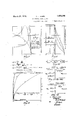
pedancei ,simulating -,networks,1.especial-ly for constant lo wavelilters Aandloaded linfes. The expression constant la will be explained' presently. a fg 15,1 fj" :l IxThe invention will be `betterhunderstood byreferencetothe following specification andff the accompanying drawings .infwhich`Figa y ures"1a. ,}2a and 2b show-sections'of thesim` vl l pleFconstant-s? wave lter..Figsiy'byla n and 4b are: sections of the vM-type ofwave lil-f;
NoiifmoniltiinioamTELEPHONE*Nn' p :f
ters described :in'my article mentioned-above.
Figs;v 5a,15b, aandb arey sections ofinynew ilterfas compared with those of the! simpler forms from ,wh-iena isi derived. Figsaldn Y 1* and 12 relat'etothe connection oftwjo yhalf.
sections .forpurposes hereinafter described.v f
Figs. 13, 14 and 15 show a similan combina-.
tion, but in ainodified fornil"y Figs-116,117
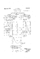
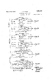
and 18 give the characteristics of such com-- binations in k comparison `with those 'of lsim-y pler design. Figs .v 19 to'24 showmore specificA applications of iny invention to adapt themV forcertain terminal, conditionsVV ITigs'.-A 251 and 26 are diagramsiof-Yafnetworkfof the press i 'ent invention employedA to simulate the im.-
pedanceof a constant `W'wave'filter, and
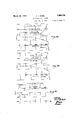
of ay loaded line.; 28, 29,30'and531arc f curve," diagrams i showing/ the Inode'jof Operal more particularly'a low pass filter, ig. 2T isa diagrainof a network ofzthefpr'esentlinfy vention employed tolsimulatetheinipedance isfgiven in myj articlel in -Tlie-V4 Bell will be made in particular to the laddertype Y of structure in which el and z2 are .the series and shunt elements, respectively. f
A mid-series section is that part between 5 the midpoint of one series impedance .al and the midpoint of the next series impedance. It has the three impedance branchesV -1-2 1o i 2" an 221,
and has the structure of a T network as-shown in Fig. la. Its image impedance at each end' is the mid-series image impedance Vl.
the midpoint of the next shunt admittance;
It has the three impedance branches f22, ,al and 222 and has the structure of 4a 1; network W2. Both of the 'above sections have the-same transfer' constants, T, as we should expect` since lboth sectionsfrepresent one .fullinter'jV val of the' `ladder type structure.
' Amid-half section is that unsymmetrical Y part between, the midpoint of one series impedance and themidpoint ofthe next shunt admittance, or vice versa as shown in Fig.
are,`respeetive y, W1 and VZ, or vice versa. Its transfer constant Vis one-half that :of a full section, `mid-series or Tnid-shunt.` Ob- Viously, two mid-half sections when connecte'd' with like image impedances, W2 or W1, adjacent, will form the mid-series or,`
mid-shuntsec'tion, respectively.
" Formulas for the transfer constant T,of a full fsection and ffor the 'mid`series *and mid- 40 shunt image impedances, VVIandNVZ, are
c; in cosh Tell-2.22
al parameter' Am. V*The relations between Athe y rifs'eries'f and shunt` impedance'sgof thefmore From'anyladder type network, el, z2, it is ipossible v"to-derive a more general one, el (m) s2" (m), which has the same mid-shunt Amid-shuntse'c'tijon isthat part between the midpoint of one shunt 'admittance 1/@2 and` as seen in Fig. 2a. Its image impedance atV each end is the mid-shunt image impedance 2b. The -i-ma e impedancesat the two ends` such inverse impedanees.`
general `derived network and those of the prototype are Y Y gli :man
At the limit, m: 1, it reduces to the prototype. (The exponent prime refers to the .case of mid-series equivalence. l
o, Mid-s7mnt derivation image' impedance,W2, as the prototype, but
fa transfer constant,T (m), and a mid-series image impedance, W1 (m), which are func- 35 tions of aparameter, m; The relations between theseriesV and-shunt impedances of the more general derived network and those of theprototypeare ,v
Theparameter, `m,\is .usedvto denote its assoc1at1on'-with mld of' midpoint 1mpedance since midpointsare considered here in ladder type networks'. y Y
.Alcoxnparison' of Formulas (l), (c2) and (L3) shows that -forthesame 4value of m both derived networks havethe same transfer constant, T 4(fm) and 'Y arm) on) =a" en) a om) W1W2=-`W1 W2 :51323 theqseries and shunt impedances of one de rived structurexare inverse networks of im- `115 pedance product, el z2, ofthe shunt and series impedances,respectively, ofthe other. Similar1y, the ypair of impedances, W1 and W2, and the-pair, Aand W2'(m), .arealso onetemtr@wave-#Kiers y l"The constant 70wavefilter of any class ,is a ladder type network of"reactances in n which the seriesimpedance, elk, and shuntim 125 pedance,"` 22k, have the relationelk z2k=k2= ak `constant,indepndent oli-frequency; (In this and what follows the` additional subscript,jc,
i Y rzkThe any vc'lav'ssare Y the two structures.derivedifroin the con-V 'Whemhe'r ig dissipation@ mediamente; the relation zlgzglifRZj-is(strictly Satisfied 'by requiring that the fcondenser dissipation constan@A d', be equalto the coil dissipation constantyclyfol" each paiifof"ipnifers'enetwork Computationsfofthe ansfery constants of this andother Sections roIn'th'e anti-cosh Y formula are Vreadily made by means of formuj las given in a paper by mein TheBe'lLSySt'em n i Y o k l A .1.
H d"Ihc'sestructuresdfreirlnid-half sec-w..
` Y tions arevShOWn in FigS, ag,` 4a and 4?).f
` Inverse network relations hold between the stant k. Wave -filtergof that, jc1asj',rv assumed knoixfmv by applying'gthe 'operationsy repre f n sented in generalQFoiInul-as7(2)fand (3)#ofA the:incid-series andxmid-shuntderivations L Where the prototype is the oon"slta'lltc?rv Wave filter, as inthis case, Ihav usedfthel'ettei'fM in the terminology ofgthe Qderiy'ed structures to denote its connectionlwithithleeinglefpaseries derived ladde ftype tom'id-Qseriesf MT The mid-series .ML-,typefhasfthesanie n'iidf ser-ies fconstant W,section-whiehis lnoi-ca` function of m; its mld-shunt image wrim'pefd- -l *shunt derivations. f *e ance",ZK(m),fis,l howeyer, a.' function The mid-shuntMY-type has the Same mid shunt image.i111pd1Ce,W2k as the mid@ n shunt constant7c section Which V1s not-a` `function of mi; itanndserlesfimage impedance, Wik "(m), v is," however, f a function of m;
'u g(.m)= srameirforrnlila as in (5), v(i6) Y 1/1 i U15-P11715 and. i
series and shunt impedances of these M-type'sff Y Mtype' wawejjltews For this` structure, (Bell System' Technical" i Y @85 7 iov.;
Thelltype Wanze'filtersl of any class are the two stiuotuies derived'from the'Ml mulas (-2),.and ofthe Inid-VserieS and mid- K tures.U rffnthese"y fnewi derivations, the g par*y rameter l@1v/'ifs` usedlt'o 'distinguish 1t fromj the v `par'anieteij m" aheadyfcontained fin-theil\=type 'inlpedafncea Since" ,bothgparalnete's` c'jfand Y im@ appear in the'-'inupedancesv offthesewnew ,1525 l sen.' Fundamentally theSewa-ve filteifs'are Vstructure,sfwhich are Vderived,from thefcon-v` 'i p stant la Wave iltferzintW'Osteps bythe kalten-fy j xrnidlsreriesl andfinidf k513-01 o.
structures,ftheltitle,MMGtypeg has been; cho?. a
nate vapplication of the.
11`5-` f type "ivave`filteribfthatgclasaby 'applying the operations represented v.in general-For- 60 ,Y i Y Thef'transfer'constantfof.eitherlrnidlhalf Aso ing value Wgdm, m=1)=W2k. i y
The mid-shunt MMftype is derived from 5 the M-type having Formula (5)V byrusing the operation of the mid-shunt derivation Formulas (3) and parameter Vm. It has the saine mid-shunt image impedance, 72k (m), asthls M-type which is not a function of m; its'` n has the formulas Vmid-series image impedance, W11( (am, .m)1 is,
however, a functionV of'both m and m; It.
These structures are shown in Figs. 5a, 5b, zipandblV 't The ser-ies and shunt impedances of one derivedstructure are inverse networks (of impedance product Rf). of the shunt and series impedances, respectively, ,of the other. Also Wlamwnm) Comparison v,of `Forrrnllas T and 5 shows that the ltransfer constant of the MM-type is the Isame as that `of an M-type whose parameter is the product,"mm.
It will be noted fromrFig. 7 that the steepness in the attenuation of my new MM type wave filter is much greater than for the M- prototype filter, and still greater than the feonstant la type for the particular values of the parameters chosen. It isthe property, however, of this fMMtype, that the frequency of infinite attenuation lies rather close to the cutoff point after which the attenuation fallsoff.- In cases, therefore, where' it would be desired tov x have the attenuation quite high for regions Vremote as well as close to thecut-oif frequency, it is desirable to build a composite filter made up of lone or more sections of the combinations of the three types represented in Fig. 7 The new type disclosed herein lends itself readily tosuch composite o structure for the reason, as appears from the theory, that theimpedance irregularities can be-made zero. More specifically, the terminal wave filter networks to be considered can all be connected on the imagevbasis with the Vconstant k7V wave filter, considered as a standard wave filter, orrany other wave filter having an equlvalent nnageimpedanceVlk or "Wgk- There are two of these composite structures, here tobe d isclosed,.,l designated midse'ries orlmid-shunt, depending upon whether cosh Tk (an, mr)`=same formulaas n maar,
y, Y Y y Y j section is midshunt termination of the vconstant lo wave filter. Y
The mid-,series general terminal wave-filter networkisin'ade uplof two different mid-half sectionsLthat ofFig. and thatof Fig. '66, connected in tandem with rin'iage impedances W@ `(vityadjacent,asshown. in Figs. 10 andV 11, y 'This gives ra composite vivave filterV structure whih has ajtrans'fer constantV equal toy glTammTaami] and image impedances VVik and TikV (mmf), "as showni'n Fig. l1. The terminals having thefirnageimpedanee W11,
are to connect with the wave filter proper whose image impedance is Vik, and the other y theyaare to connect `with the mid-series or terminals having "the, imagel )impedancey e'qies' thevaluesof yy attvvo non-'zero'valuesV Y of Uk'as already stated,"Forfgeneralityflet Y I y g the krequire'mentsheyj '1 l fl ternetworkis made/11 fof;themid-'halffseo-4 y tionsf ofFig. lb/'ands 4i,g,f.' -5b, oonn'eted finV tandem with image impe'dances `Wm (m) adjacent, as shown infFi'gsLflS 'and 14. This f givesA a composite Wave filterstrnctuevhioh has a1 transfer constant 'equaly to jabo've,
are to connect vvi-ththe lxtfahpe; Afilter-v pifoper whose image impedance W2 k,end the other They terminal klrinllazfg iymlpfj ences i (7) mdnhemiq however, ,in Athosefch infactefristics vvhich .rep#
l vSuchen approximatelyidel1ehir1cter1sn` o "40,isgobtainedlby'requiring these v ancestro havethevalue Ratftworepresenta tive points ina transmitting bandother than .at'Uk=O. This fiXesfthevaliijesof thetwo parameters m and fmlf and definitelydeter? mines the entire. general? A networkofzlkefand i 22k, assumed Llknownf Y The proeeduefoi` dete lminingthe paiin-r` eters m and m is as follows :1-'We hve'from mmm tam and. hlt-mgm?. y
Since m Vand Vm" 'lie betyveenlzepo and lnnit'v,` follows that 0 a il? 1. 'y g l'kpsgsruming no disf 'Theirsolufirgive i, Y :aft n t vSiihstitlitionsof in'(12) givestwoisimule taneou's linear equations forl the determina# am; Vd; ,n
nituvlesgofA a vand; b. Henee, tofix .the latter l i yr Anil srtion"offiheiusejof these gehr'fly- `forfrnnls] iSv DOW- givein i .After a few prelixnif Y narytrialmheirapplication,showsfhargverr satisfactory resnlts are obtained with thel re-' g, Y
Of Vcourse, other valnes in `.this neighbor-` hood'wouldlalso be quitest'isfaetoy, butthe above are the ones which willhe"'tke'nhelfe?l in the vfinal networksyfoi"illustrative'pnr poses#y The results are shownlinfF igs. 121 d' K, n
From it is Afound that the-maximum *of the 'prttype, are functions of "m'orof m and m. y
, It is evident that one l.might Vgo to filters ofhigher order' of complexity, such as MMM-type wh ich would berelated Vto the mininimvaluesoffy e y occur at the two points (skb) i a/(a-bY-iabujLaa-zb) e Y '(15) 2a() Substitution of the above values gives a minimum g/= .9857 at Us: :3696 and a maxiinning/:1.0198 at Uk=.8297. Thefch'aracteristic of g/ is, shown in detail in Figi 18 on a much enlarged scale; The real part is seen to depart less than 2% from the ideal value of unity and the imaginary part, due to dissipation, is seen to be very small. It should be pointed out that other characteristics than Aan approximately constant y are possible from the above general' formu- The derivations and `discussions `thus far have been on the basis of using a constant k filter as the prototype bit -itis `vident that any ladder type of Astructure might be usedi'nA4 which the serieseleni'nt is and the `shunt element is e2. Thus if the-load is not ajconjstant resistance but is a function of frequency sen-sa" i then somethingorther thaii the constant filter might 'he indicated and the filters of l higher order, analogous Vtoy the M-tvpe orthe MM-type, wouldbear the same relationship to this prototyp'egas those already seti forth.
1' i e ln this case would bereplaced in the various equations by 1/ so that Equation 9 forex'-` beraadt morefevidenit by taafondwipg tablewhich wil'lbe VVfound to be y'consist'eilt' with Figs. to Gbfof the drawings.
, if-Coininfg back to sidered, one of the advantages of MMtyp'e .iln these relations all the als, except'tihose MMtype in the saine Way as the latter isre- V"lated to the type vone order lower. N Vhile Vsuch types will have impedance characteristics which would be considered *as improvements over the types of lower order, in 'pracltice, I find that the increase in complexity is such as not'to warrant theorder higher than MM.
the particular Ydesign Con- `isfthe iinprveineiit which it shows over the M- type from the standpoint of'con'sta'nt Vimage impedance over the transmitting band, this improvement over the fM-type being siniilar to that which vthe Mtype shows o Ve'rthe constant le type.V (See Fig. 9.) Infact is 'this improvement inthe impedance charac- "agation characteristic, such 4as a 'given "steep- `nessof attenuation outside the transmitting -lban`d, `be` obtained with an M-type filter ".o'f appropriate value of ""m. The basis for :iin-proved impedance characteristic lies inithe A`tejristic 'which constitutes the chief advantage Y Cof the MMC-type' rfilters; for the desired propthere `would be three parameters and there f fore opportunity for still greater choice'in impedance cha'racteristief, VBut lagain it Eis to the same time to connect .properly to a constant lc filter it will befnecess'ary to have a :maiali-ietwat@ Series al Shunt e2 M type 'Series Miti/pe be borneV in Vmind that thefsafme propagation Ieli'araicteristic iria'y beobtai'ned with lan M- oorvrlpositing y-lli'nliiioff three half sections iin-l section of MMetype gives a double `lineup or tworegionsfof infiniteattenuation, (see Fig. A l l l 'Where 711k. must'alvvays be positive for itis e A12) so three half sectionswould t, give v'three i tion'witlicomparatively high attenuation be lineups or threevregionsof in'iinitefattenuatweenthe lineups; YThusr 'afhighy kattenuation is maintained froma region very close tothe transmittingslr band Ito aregion far removed therefrom Where the attenuation tothe prototype is itself high. Y i lIn the graphs. ofrFigs. 7 to.9`and'16 to 18,y
e itvwilliloe noted Vthat Ug'has "been used rather tion of the curves.
` than'freqnency. Tliis'isa matter otfconven-V ience only and still permits ready interpreta- :More strictly, the relationis 1 ,-UeJferfe se f lItispossible at any to reduce these curves to a frequency relation-since thefzfreqnency is a function `oi elle/422k? j.-Tln1s, 1n af1ovvpass inefheee eemefrigejvie sein ie reis, there effect of dissipativeresistance'isshorvn bythe l dotted lines. In a non-dissipative, L"nniltiple j band, constant In wave vfilter, Ukiranges with Vio increasingirequencyffrin Oto-` :l inza loW- pass band; fromV -l' to 0 and 'back to 1-71 in Y quencies belowl thisfpoint *of confluency it is las?v This is determinedfby thesigniof Ver upon the introduction of sr'nallpositiverdijsr -sipation Let us allovvdiss i WhatInay bel termed a highQpa-s's branch,r `While at frequencieseabove; it lisga lov-pass` branch. All transmitting bands of `a con stant la?? Wave ilterinay thus beregarded as made up"of single or confluent low-passend high-pass branches. Their distribution onj1tlie` fre'- quencyscale depends f upon thef'i'ela-tion bee? tween Uk and frequencyA i The difference between thecharacteiistics offaloW-pass branch and a1high-pa''ssbjranclny e .i e e .e i e y e Y f e .e .l Y shown inFigsptoQ or Fifrsrlfto 18-rom although similar functions ot Uk 1n both Uk-,to.fbythefrelaonbwenUk and f K s sho/Wn ein each case. It may alsobefadded y: thatany two-terminalqbranch, of threeor`v`r` branches, is `mainly dueI to" a proper choice Vof signforthe phase constant inthe fiin'ui ipatiQninall ele .dissipation constants foreach pair ofeinversej to positive resistance yindaj1k `'fhen'fro1n thatwlk is ositiX/e orne ative de endinO' upon:Whether it isin "loW-'pa'ssv or afhigh pass'branch; also the phase constant has pass branch and Vnegative .e in a high-pass the sign'o Vk. vHence, Bt positive in a lovve` 840 branch, being of the/ same magnitude 'but"op positein signfor the samevalue ofjUkbiit opposite valuesfof .,Vk. In the ldrawings, the
general efect'of'jsmall ldissipation,'en the above basis, *is shown; by assiimingfthatl Vk`=jiQlUk- VSingle characteristics i repref if sent both branches,`vvherein"tl ie propers'igns ai yfonthesaine class'ofvwavefiilter;
-aryto 'be taken for-:the phase constants and the'freact'ance components of'theffiin'ageiIn.-
ped'anc'e's introduced by.''dis si-pation.;'V The samel considerations holdVV also forftliei M-typesfand' MMCtypes' as iunctions of Ukl berof sectionsof'lone kind may beconnected in series, or sections ot'diii'erent kindsfina'y be Vconnected inseries,''the requiremefnt` being that the image1 impedances shallv match at each j'LinctionH'p'oint.y Tofillustrate furtherf the use fof' the abovev` general results,` rvthe net f l Works .of F 12/and lvhavebeentranslated into *the designsiwhich Vthey might'as'sui'ne for three importantclasses.;l The ,low-pass 2O gjthe high-passinFigs. 21 and 22; "and case, the magnitudes ofethe elements ofthe 'constantkfwave filter are obtainable from Welll known "formulas, 4and vit vvillfebe` noted y ios i terminalnetwork/s-are shoyvnvin Figs.v 19 and thatin these, as Well'as-in fall of the nevv'filter s sections, the seriesand shunt elements are si Inadeup of combinations'of @ne and eek, the
series and vshunt impedanceseof the fffconstant 70; Wave filter of any classethatis tlie .l oW pass, `thehigh-pass, the band-pass filters, etc.'r The icharacteristics'of theicircuits ofFi'gsQlQ gz 12C. e
tol 24 may be V expressed las afunction of the `frequency;c byftranslatingfthegeneral. curves `more elements maybe 'giveny other yformsfby equivalent Vimpedance ytransformationsp such n -as givenjinffmyfarticle 'oti'Ilie Bell',V System' U Technical Journallfor yl January, 1923; yre- Y Y ferred toabove;
'A i' may be introduced between'the constant 7c leaves the transmitting band.
" `Freni the above description, it will be seen that I have devised a typeof wave filter section which shows an improved impedance charactertistic in that it hasv more nearly constant image impedance throughout all transmitting bands thanY either the best M type or the constant 7c, wave filter, and this impedance is nearly a pure resistance. (See Fig. 9). Further than this, the section has a steeper attenuation characteristic as one V(See Fig 7)- Finally, it lends itself favorably to the building Vup of a composite filter by a connecting i of the intermediate type such as the M-type.v
t thejunction of the two half sections, the iina'ge impedance will `be 'the same in both directions so thatthere are no irregularities. To this llink on the one sidemay be connected V e the load of constant resistance R and, on the simulated.
other side the'constant 7tfilter or as many sections of any desired type to give the overall propagation characteristic desired. Thus sections of the M-type of different m values type filter and the compositing link or terminal wave filter network without imped-' ance'changes or irregularities at the junctions ,as seen from Figs. 3a and 4a. Itwould also be possible, Vlout not sofp'r'actical from a cost hasis,'to insert sections of desired characteristicsjbetween the two halvesfof the compositing link," or even to'introduce such sections between the link and the load. Also while the explanation has been made in con-A nection with a definitel filter it is equally applicable .to loaded lines; which may be looked upon as ladder structures. l 'ff' The filter" sections .of lthe Ykinduherein disclosedinay be employedadvantageously in networks to simulate the impedance of certain transducers; a few examples will be disclosed in-connectionwith Figs. 25 to 31.
Tosimulate the image impedance of a constant-c wave iilter with mid-series termination, a network section such as shown in Fig. 12 may be closed across its right hand pair of'terminals by a pure resistanceof value R: 7c, then its impedance across theleft hand paii` of terminals will closely simulate the` wave filter impedance. Such a simulating network is shown in Fig. 25, in which .211g
and 22k are the series` and. shunt impedances respectively of the constant 7c `filter that is lf thisfilter is a low pass filter with each series impedance elk embodied in a series in# ductance L11. and each shunt impedanceembodied in Va shunt capacity C21., then the simulating network takes the form shown in Fig. 26, which will be readily understood on comparison with Fig. "19. In case it is desired to simulategthe impedance of a high `passfilterV with mid-series termination, the
resistance R will be put across the right hand pairof terminals of the network of Fig. 21.
In case it is desired to simulate the imped- ,ance of any constant 71; filter at mid-shunt termination, the simulating network will be Vrepresentedrby Fig. 15 with resistance R .be built up to simulate the impedance of a high pass filter, Vthe procedure will readily be understood for other classes of constant 7c filters, starting in each case from Fig. 25
or from Fig. 15 and a resistance R, vand making use of the known forms of en. and 22k.
1 Fig. 28 shows thedegree lof simulation as computed Vwherein the impedances are functions of the generalv variables, Uk and V1.. These variables are defined by the impedance ratio.4 l v f The variation of the impedances with respect tofrequency depends upon the relations be- Vthe range Vfrom Uk=O to Uk: *1, the networks simulate Wlk and W2k Within a few per cent.v Neara critical frequency, where Uk= 1, thesimulation is improved by dissipation. In the attenuating range the simulation is still quitesatisfactory, this is because the networks have considerable attenu frequencies between each network and its terminating resistance R will be vreduced in transmission and the impedance across the f ationin the attenuating bands sothat the Veiiects of the impedance irregularities at these other p airof terminals willapprokimate W1k v or' W2k, respectively.
VLoaded line impedances may besimulated f advantageously by the use of the vnetworks `herein disclosed. It is a well-justified assumption that either midpoint impedance of y a loaded line in its principall transmitting sponding midpoint impedance of av constant f 1'0- .shown in Fig. 2
band is approximately equaly vto the correa low-pass wave filter as the basic network, with the 'series addition -of the impedance of a supplementary network which simulates the additional impedance introduced by dissipa-k tion at low frequencies. Allflierefo're the prop-v er complete network to simulate a-loadedl line will consist of a series combination of a basic network and a supplementary*network each of which will now be pointed out in somev detail. If the loaded line impedanceV is to besimulated at midload, then the basic vnet-4 work will be as shown Fig. 26.'.If the` simulation is to be .at mid-section, `then `the basic network will be las shown yin Fig. with the .right hand pair ofk terminals`c1osed, through a resistanceR. InL eitherv casethe supplementary netwoikwill be the. same; it contributes substantial impedance only at the lower frequencies of the transmission-range of the loaded line. This will be pointed out presently in connection with Figs. 29,30 and 31,especially Fig. 81. p Y
The supplementary network mayhave dif-1 ferent forms; a good one for' the purpose is complete simulating network for vmid-load terminationof the loaded line; For mid-sec1 tion termination, the supplementary network vwould ber the .s`a1ne, 'but' the basic network would be as shown in Fig. 20 with .al resistfV ance R -across the right hand pair of'termi# nals in Fig. 2O.
certain primary lineand coil data. This takes formulasV to section. l The mid-load iterativek impedance,r is giv-` The magnitudes of the-elenients/.of these networks are all determined from the actualV vloaded-line impedances as computed from the formulas (or perhaps measuredsas sending-endimpedances) instead of directly from account of variations with frequency'of the constants, suclifas line leakance and loadingcoil resistance. Theshunt capacity of a load(- ingu coil is assumed to be concentrated, half at each end, and each half is added fin the" the line capacity of the .adjacent enpby lthe formula and there is a corresponding formula for-'the mid-section iterative impedance.
' n Referring to Fig.- 27, the magnitudes of the where it is labeled supplenientary network. L This figure shows the Y elements of the basic network are Vknown when R and f2 are known, R being the impedance,-
\/L1k/ and f2 being the. critical or cut-oit` frequency of the loaded line. Accordingly, L1k=R/1f2` and C2k=f1/1rf2R. kThe impedance in the es-A sential y'frequency range is given quite' accurately byv i Z1R^\/1 '(f/f2 2;f7
This relation will be used/for design purposes.
The values of Rf and f2 are here determined for any particular` Vloaded line by assuming ...any de?, Y 1 e f v and Y 'fbi if Y (1 9) fr?? Y ra Y A u 'The actual impedance,Z1, of the network" with these `values may be computed as for any finiteV network. AA y computation similary to y the foregoing may be made for the basic networkfor a mid-section yending of the loaded line.
The Vsupplementary network "of Fig. 27 ,Y has animpedance` expression of the form Y Y The resistance and capacity elements are obtained from 'the above impedance Vcoeiitions 1sk a., fab. fac. :i
ton indicate the lmethod of designr 4With 'the above formulas we can proceed' d i lo:
impedance characteristic.V These other forms 60. i l These give from (19) R=l564fi ohms,
Idea-llyvthe network should have the im* pedance characteristic close agreement in these values for. mid-load z and. mid-section their approximate: mean Z www i values- Will be taken, and the results will be Totix the four impedancecoeliicients, assume applicable either tor mid-load or mid-secthat the network has the ideal components tion, without substantial error. Accordingly, thedesign will( be based on. the values R:` 1565 ohms and. f2=5635 cycles per second..
01"(23) at two important low frequencies, the data with increasing frequency being,
These give L1k=88i38- mh.,l and. G2k=-03611 f1 WW1? mi. we have then for the. mid-10aa basic f2, i Wgr rlhese values-are to be substituted,iny (22)` to ity-elements), obtain four linear equations. The solution a these linear quations gives L1k 31.95 mh'., @2k-.01845 mf., 'a'lflwlbffnbg; 1 (24) .16461 nfl/s55 mii.; a=7-1 b1 flmibzjleml/fl, .1494 L1k=l320` Inh.;
mid-sectionbasic network.
The impedance characteristics of this midwhere i :f
work constants. can be computed. by Formuu Workgqthe results me Shownrin Fig- 30; las (21). The. IletWOrk impedance iS H1611 Increasing the amountf of dissipationin given at any The actual impedance simulating K1 is sum, Zyl-e. Y at the upper frequencies.
The procedure for thezsupplemental'nethaslbeen madefrom` low frequency will be apparent from the foregoing. supplemental network has the same form ('l' 2.1) and (OTZJ Where. and Z2 foreither ending,n mid-load o r mdesection. -f'
It should be pointed outliereJ that the supplementary network may, if dcsiredbe given; other structuralforms havingtwo resistances andtwo `capacities and having an equivalent E and Z1 have to midload. The dataare Y f1=100, 73+2`m1=152f 700,: o 7%:3005 rzlimz: 2O-I 252. -Fro-miFormulasf ('24) We obtain.
0=7839.0; L1-23312, b1: 171600-10-2 b2 301481104. From (2L) these give R1 =5327. ohms; @2:38861 mf'. ,t G3=`2;08 mf.; 'R.=7839 ohms. The impedance characteristic as computed fromFoi-mula (20)` is shown in Fig.l 31;
maybe obtainedA by transformations from the known one above or their` elementsA determined `from other formulas Vcorresponding to those ot.'` (.21).v V
Likewise, a supplementary;network which has a smaller or larger number of elements than the one above might be usedsatisfactorily with the same basic networks;` That depends upon the low-frequency impedance characteristics of the given loaded 4line and pontile closeness Ofslmulm'lon dpslred" the complete simulating networks are comgpfye veltlrlllg pared with-those of` the loadedline' in Fig; 29. ,e -a design Wm hem be outlined fox a gauge Simulation i., within .7 pei cent. of the nn B-88e50 loaded side circuit: 9 Dataior: the mid-load bas-ic network, taken llto from computations for K1, are
fa=3000, Ta=1324 in the case of the mid-section network. This and 'f{,"=5`009g rsf-720) and" of the' criticalw frequency, 5635 cycles per second. V
7225632 cycles pers'econd;`
lVhat isola-uned is: v
It the values otra and mare computed likewisefor'midesection instead oflmidfload, they f2=f5638 cycles per second. Y Because of the.
network of Fig. 27, the inductance and capac-j andi a corresponding set of values forI the load basic network of Fig. 27Y and t'hecorre'f spending mid-section basic network havel From the values ofl 0&0, al, 1 and b2 the Ile'- been computed' directly from the finite net frequency by Formula (20). thelreact'ance-elementswouldtendtoincrease the" the freactance. components of this impedance V The design of the supplementary network work to simulate impedance at Vmid-section OfFigf 27 The data representingA the average valuesof."
have the same relation to midsecti'on that' Finalresults showing the characteristics of pedancc over the continuous range' from 100 cles per second; the per cent'. accuracy is best"y upper frequencytis lapproximately 97"per cent1..
l. A waveilter. ofy the MM-type in which.V
will be found to give R41-1564.6 ohms, and the series' and. shunt' elementsof. a. section Li.
v elements of the M-type bear the same relation to the corresponding filter that the vM'etype bears to the constant c t 7pe 2. A wave filter of the MM;f-type in which the series and shuntk elements are `related to the corresponding elements of a constant lo type filter by the two parameters m and m;
3. A Wave filter of the ladder Vtype and related to the prototype y the series element and the shunt elementbeing each derived from the elementsofthe prototype as. definite functionsv of two arbitrarilychosen parameters m and m. Y
4.7A wave filter ,designated as MM-type in which a mid-series section has the series element equal to the series element yof the M mid-shunt multipliedbya factor m and has the shunt element equal to the series ele'r-y i ment of the M mid-shunt multiplied by 4m e plus the shunt element of the Mffm-id-shunt multiplied by .i
5. A wave alter 0f thcejiadder type inwhieh the series and shunt elements of a mld-series section are relatedto the series` and shunt' elements of 2,1 and 22'. of a mid-shunt section of an M-type filterY insuch manner thatthe series element is equal to .21m/n and the shunt element is equal to in seriesV with the el itself being equalk to m21 in parallel to and the a2 being` equal to 1 l. zzm
Where 21 and z2 are respectively theseries and shunt elements of a ladder lter and m andV m are constants for any one lter. Y
6. A wave iilter of the ladder type'in which the series and shuntelements of a mid-shunt .y section are related to the seriesand shunt elements of el and a2 ofa mid-series section i of an M-type filter in such manner that the series element is equal to elm Yin parallel with.
, 4cml L and the shunt element is equal to where and e2:
constant cv filter,
the-e1 itself being equal to aim and thee-2 Y being equalto f l vare respectively the series and shunt elements ofa type of ladder filter and mand m are constants for any one'filt'er. A wave lter of the MM -type in'which theseries and vshunt elements of a mid-series o'ra'mid-shunt section are related to theseries and shunt elements of amid-shunt. orar mid- Se'ries section of an `M-type in the same'way that they series andgshuntelements of a midseries or ay mid-shunt section of an.-M-.type filter are related to the seriesl and shunt elementsof a constant 7c type. f 8; A wave filter ofthe MMstype in whichy Icorresponding bears to' the constant k type, the imageim. pedance of ,the section being substantially constant overthe transmitting band.
9."A wave` filter of the generalM-type but of higher order of complexity, the wave filter bearing the same relation to the prototype flltergone Vorder lower thanY the M-type of ther first orderrbears tothe constant la type. 1017A composite waveflter of the' MM- type as described inclaim 1 and the conf the fseries and shunt elements of a section bear the samel relation'to the elements of the M-type filter that the M-type v noy stant la ltypevcharacterized by the condition that there shall be no impedanceirregularii ties at the junction of the sections. Y
11. A composite wave filter ofthe MMy -1 i type as'described inclainr 1 and' thel con-` stantlc type, a connectinglinkbetweenthe two portions, each side of saidlink having the limage impedance which matches that of the filter with which it is to be connected. 12. A composite wave filter of the MM(- Ilm type as described in claim 1 and the constant 7c type, a connecting linkbetween the two portions comprising two half filter sections one half section Vhaving an impedance ontheone side to match the MM-type section the other half section having an impedance on the one side to match the constant c type section and-the other sides of each half sections having equal image impedances. 13. In a composite wave filter, a connecting link with an impedance on the one side matching that of a constant-7c type filter and on the yother side matching that of an MM- type.
14. In a composite'wave filter, a connect-r ing link with an impedance onthe one side matchingthat of a constant 7c type filter andon the other sidey having an impedance of substantially constant resistance over the transmitting band.
the one side matches a mid-impedancel i of anM-type filter and on the other side" matchesz a mid-impedance of an MMftype. 16. An impedance simulatillgY network comprising a networksection composed of two half sections; one of M-type and the other of MBT-type, and closed by a resistance.
A17. A network toV simulate the impedance of atrans'ducerwhose impedance is like that of ay low pass filter such for example as the impedance of a loaded line, said network compr'singtwo half sections, one andthe other of MMU-type. K n p 18. network to simulate the im edance of a loaded line consisting of an l--MM terminal section having two pairs of' terminals, a resistance across one pair of terminals, said section and resistance forminga` basic' network and a supplemental network p inV series with' the otherv pair of terminals, said supplemental network being adapted to develop impedance principally at low frequencies. 1
19; A networkto simulate the impedance of a transducer whose impedance characteristidis of the general type of a constant'k ladder type filter5 said network comprising the networkshown in Fig. 25 in which 21k is the seriesA impedance or" said constant 76" filter and .22k is the shunt impedance thereof.
20. A network tol simulate the' impedance of a' loaded line, consisting of the basic network and the resistance R- and the supplementar-'y' network of Fig. 27 combined as in said igur'e;V
In testimony whereof, I have signed myv name to' this specification this 24th day oi November, 1930. A 4
Y OTTOl J. zonL.-V
o'M-type i i
Priority Applications (1)
| Application Number | Priority Date | Filing Date | Title |
|---|---|---|---|
| US498161A US1850146A (en) | 1930-11-25 | 1930-11-25 | Electrical wave filter |
Applications Claiming Priority (1)
| Application Number | Priority Date | Filing Date | Title |
|---|---|---|---|
| US498161A US1850146A (en) | 1930-11-25 | 1930-11-25 | Electrical wave filter |
Publications (1)
| Publication Number | Publication Date |
|---|---|
| US1850146A true US1850146A (en) | 1932-03-22 |
Family
ID=23979836
Family Applications (1)
| Application Number | Title | Priority Date | Filing Date |
|---|---|---|---|
| US498161A Expired - Lifetime US1850146A (en) | 1930-11-25 | 1930-11-25 | Electrical wave filter |
Country Status (1)
| Country | Link |
|---|---|
| US (1) | US1850146A (en) |
Cited By (4)
| Publication number | Priority date | Publication date | Assignee | Title |
|---|---|---|---|---|
| US2662216A (en) * | 1949-06-01 | 1953-12-08 | Hartford Nat Bank & Trust Co | Electric filter network |
| US2737629A (en) * | 1949-04-12 | 1956-03-06 | Int Standard Electric Corp | Equalizer arrangement with an attenuation characteristic proportional to frequency |
| US3135930A (en) * | 1961-05-12 | 1964-06-02 | Bell Telephone Labor Inc | Impedance-simulating network |
| US4453145A (en) * | 1982-04-10 | 1984-06-05 | Licentia Patent-Verwaltungs-Gmbh | Band pass filter |
-
1930
- 1930-11-25 US US498161A patent/US1850146A/en not_active Expired - Lifetime
Cited By (4)
| Publication number | Priority date | Publication date | Assignee | Title |
|---|---|---|---|---|
| US2737629A (en) * | 1949-04-12 | 1956-03-06 | Int Standard Electric Corp | Equalizer arrangement with an attenuation characteristic proportional to frequency |
| US2662216A (en) * | 1949-06-01 | 1953-12-08 | Hartford Nat Bank & Trust Co | Electric filter network |
| US3135930A (en) * | 1961-05-12 | 1964-06-02 | Bell Telephone Labor Inc | Impedance-simulating network |
| US4453145A (en) * | 1982-04-10 | 1984-06-05 | Licentia Patent-Verwaltungs-Gmbh | Band pass filter |
Similar Documents
| Publication | Publication Date | Title |
|---|---|---|
| Zobel | Theory and design of uniform and composite electric wave-filters | |
| US2076248A (en) | Wave filter | |
| Norton | Constant resistance networks with applications to filter groups | |
| US1850146A (en) | Electrical wave filter | |
| US2392476A (en) | Wide band phase shifter | |
| US2342638A (en) | Wave transmission network | |
| US1828454A (en) | Transmission network | |
| US2249415A (en) | Wave filter | |
| US1781469A (en) | Wave filter | |
| US2238023A (en) | Equalizer | |
| US2035258A (en) | Wave filter | |
| US1955788A (en) | Transmission network | |
| US2360932A (en) | Negative resistance loading | |
| Filanovsky | Enhancing amplifiers/filters bandwidth by transfer function zeroes | |
| US1636152A (en) | Wave filter | |
| US1557229A (en) | Terminating network for filters | |
| US2932804A (en) | Transformer system | |
| US1600290A (en) | Wave filter | |
| US2058210A (en) | Wave transmission networks | |
| US1951026A (en) | Polyphase transmission | |
| US1610336A (en) | Circuits for passing or stopping a frequency band of alternating currents | |
| US2043345A (en) | Wave transmission network | |
| US1853969A (en) | Circuits for coupling lines of different impedances | |
| US1920041A (en) | Electrical network | |
| Prabhavathi et al. | High-Q resistance-capacitance ladder phase-shift networks |