US1850140A - Continuous rotary separator - Google Patents
Continuous rotary separator Download PDFInfo
- Publication number
- US1850140A US1850140A US328637A US32863728A US1850140A US 1850140 A US1850140 A US 1850140A US 328637 A US328637 A US 328637A US 32863728 A US32863728 A US 32863728A US 1850140 A US1850140 A US 1850140A
- Authority
- US
- United States
- Prior art keywords
- shaft
- basket
- gears
- clutch
- knife
- Prior art date
- Legal status (The legal status is an assumption and is not a legal conclusion. Google has not performed a legal analysis and makes no representation as to the accuracy of the status listed.)
- Expired - Lifetime
Links
- 230000033001 locomotion Effects 0.000 description 7
- 230000005540 biological transmission Effects 0.000 description 4
- 239000000463 material Substances 0.000 description 4
- 230000007246 mechanism Effects 0.000 description 4
- 238000001914 filtration Methods 0.000 description 3
- 239000007788 liquid Substances 0.000 description 3
- 229910052751 metal Inorganic materials 0.000 description 2
- 239000002184 metal Substances 0.000 description 2
- 150000002739 metals Chemical class 0.000 description 2
- 101100163433 Drosophila melanogaster armi gene Proteins 0.000 description 1
- 230000002159 abnormal effect Effects 0.000 description 1
- 230000009471 action Effects 0.000 description 1
- 230000008859 change Effects 0.000 description 1
- 238000010276 construction Methods 0.000 description 1
- 230000004048 modification Effects 0.000 description 1
- 238000012986 modification Methods 0.000 description 1
- 230000002441 reversible effect Effects 0.000 description 1
- 230000000630 rising effect Effects 0.000 description 1
- 238000007790 scraping Methods 0.000 description 1
- 239000007787 solid Substances 0.000 description 1
Images

Classifications
-
- B—PERFORMING OPERATIONS; TRANSPORTING
- B01—PHYSICAL OR CHEMICAL PROCESSES OR APPARATUS IN GENERAL
- B01D—SEPARATION
- B01D33/00—Filters with filtering elements which move during the filtering operation
- B01D33/06—Filters with filtering elements which move during the filtering operation with rotary cylindrical filtering surfaces, e.g. hollow drums
Definitions
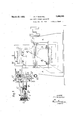
- Figure l is a side view, partly in section, of an apparatus embodying the. invention.
- Fig. 2 is a face view Fig. 3 shows a modification of the knifeactuating means
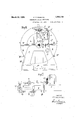
- Fig. 4 is an enlarged view showing thel knife and its carrier in diferentpositions
- Fig. 5 is an enlargedV detail of thel knife mounting
- v l 1 Fig. 6 is an end view of the knife guide and related parts
- Fig. 7 is a plan view of the reversing clutch.
- A indicates the framework of the apparatus
- one of the two standards or side members of frame A is higher than the other; the upper portion of such standard being utilized to supportl the Vvarious parts or elements thatl are provided for carrying kand mounting ⁇ the Aknife or kscraper d.
- This element has the form of a spoon with sharpened edges, andit is rigidly secured to the outer end of a hollow armor sleeve F which is mounted for endwise movement in either direction, with slight friction, in a hollow guide D1; said arm F having ,alength jsuch thaty its forward portion extends normally into the interior of basket P so as to enable the knife or scraper al to travely along the circumferential wall of the basket and shave or scrape off the deposited material.
- the guide D and associated parts have a hinge connection E with the aforesaid upper portion of the taller standard, so as to enable,V them to be swung horizontally as a unit. around the vertical pintle of the hinge and thereby enable theknife to move through the open sides of the casing and basket into and out ofthe interior of the latter, in order to be repaired, without requiring Aany dismounting; this movement being accomplished ⁇ in any desired manner.
- Y s with the aforesaid upper portion of the taller standard
- theknife is intended to travel, from front to back and vice versa, parallel with the basket axis, without stopping or reducing its full-speed rotation, passing to the rear ⁇ wall p2 of the baskety and returning kto the front thereof vwhere said basket is open and provided materials deposited in the basket against theV imparted to screw G by a system of gears and shafting operated by the basket shaft a; such system (see Figs.
- gears m and n are provided with toothed hubs or clutch portions, and are ⁇ adapted to be made fast to shaft L5 by clutch sleeves r2 and r3 which are keyed to slide on said shaft into and Out of engagement with Gears b C b n and fm, and are actuated at the proper times by another set of levers operated by a shifting rod L8.
- the last-named levers include a controlling lever L11to which one end of rod L8 is pivoted, a double-armed lever L12 to which lever L11 is connected to be rocked thereby, and a rod L13 joining the outer end of lever L12 with the corresponding end of a second double-armed lever L14; the inner ends of the two levers L12 and L14 being slidably engaged in the grooves of the clutch sleeves r2 and r3, respectively.
- the clutch shaft L5 is constantly in motion; and when one of the gea-rs fm or n is Coupled to the clutch sleeve r3 or r2 by the movement of shifting rod L8, said shaft L5 drives the transmission shaft L6 by means of the central gear r of the clutch mechanism; said gear turning in one or the other directionaccording as gear mor gear n is in mesh therewith.
- the rotation of the basket Shaft a is transmitted through gears L to shaft L1, thence to shaft L3 through gears L2, and thence through gears L4 to the clutch shaft L5, thereby effecting its aforementioned constant rotation.
- the reversing operation is preferably automatic, and is eifectedby'meaus of a slide rod Q which is connected with guide D in a manner to enable it to move longitudinally, relatively to and exterior-ly of said guide, in either direction; said rod having inturned stops Q1 and Q2 at its opposite ends, the
- the knife d must assume two different angular positions, shown in dotted lines at d3 and Z4 in Fig. 5. It occupies the position d3 during the filtering or decanting operation, in order to prevent it from contacting with the annular layer of liquid P3 which is in motion in the rotating basket and, in con- Sequence, terminating such motion.
- the other position d4 is occupied when the material P4 deposited on the basket wall is to be removed after the liquid has been discharged, either by filtering the liquid through said wall or by means of a suction device in case an unperforated basket is used.
- the rotation of arm F in order to bring the knife intoone or the other position, is obtained by means 0f a worm H1 mounted on the spindleof a handwheel K and meshing with a worm wheel H2 keyed to said arm.
- the handwheel is actuated at the moment vrhenthe removal of the solid residue must take place, or when it is necessary to recommence a filtering or a decanting operation after the removal has been effected, such operation taking place at full speed.
- the modified drive for the reversible transmission system and the screw G illustrated in Fig. 3 is independent of the basket drive.
- an electric motor is provided and is connected by gears L1() with the transmission shaft L9 (which replaces the shaft L6 of the first form).
- a spring clutch T is provided to enable the knife toslip on encountering an abnormal resistance in the basket.
- I claim as my invention A rotar se iarator. com rising a rotar Y 1 basket, a driving shaft for saidbasket, a scraper, means for feeding'said scraper back and forth within said basket7 and a connecting'shaft between said driving shaft and said feeding means, said feeding means and scraperbeing swingable about said connecting shaft.
Landscapes
- Chemical & Material Sciences (AREA)
- Chemical Kinetics & Catalysis (AREA)
- Centrifugal Separators (AREA)
Description
March122, =1932. P. T,- ROBATEI.
CONTINUOUS ROTARY SEPARATOR Filed Deo. 27. 1928 5 Sheets-Sheet 1 /A/vmm D7/P054 nu' 'By' we a March 22, 1932- l P. T. RoB-ATL 1,850,140
CONTINUOUS ROTARYSEPARATOR I Fi led`Dec. 27. 1928 3 Sheetg-Sheet 2 ATTUR/ VEJ/ March 22, 1932. P. T.ROBATEL 1,850,140
CONTINUOUS ROTARY sEPARAToR Filed Deo. 27, 1928 5 sheets-sheet 5 Figs Figs Ey l, l
Amm/v y Patented Mar. 22, 1932` rmllaflvr ori-Tice' i PHILIBERT T. ROKBATEL, OF LYON",` CE, ASSIGNORTO ATELIERS T. ROBATEL, 3'. BUF; FAUD `& CIE., 0F LYON, FRANCE,`ACORPORATION OF FRANCE YcoNr'rrNUoUs ,ROTARY sEPARAToR Application led December 27, 1928, SerialnNo. 328,63*?, and in France February 16, 1928.-
utilized for scraping oft' ythe material de.-Y
posited upon the wall of the rotating basket by centrifugal force; the means provided for adjusting the angular positionof the knife; and the means or mechanism for effecting its rectilinear reciprocating movement.
Other improvements relate to the construction of the frame of the machine as completely independent of the casing wherein the basket is disposed, so that the twoV may be made of different metals; and so that the casing, if worn out or corroded by the action` of the yliquids treated, may be repaired or replaced without. dismounting lthe mechanism or the frame.
Still other and further improvements are also involved in the invention, and will be set forth in due course in the description which follows.k f
In the accompanying drawings, n,
Figure l is a side view, partly in section, of an apparatus embodying the. invention;
Fig. 2 is a face view Fig. 3 shows a modification of the knifeactuating means;
Fig. 4 is an enlarged view showing thel knife and its carrier in diferentpositions;
Fig. 5 is an enlargedV detail of thel knife mounting; v l 1 Fig. 6 is an end view of the knife guide and related parts; and Fig. 7 is a plan view of the reversing clutch. Referring more particularly to Figs.v 1 and 2, A indicates the framework of the apparatus, and B, B acylindrical casing open at one side and having disposed within it a basket P which, for the most part, is also open at the same side as the casing; said basketV AAbeing mounted on a horizontal shaft a (Fig.
2), suitably journaled in the side members of frame A and driven from any desired source ofvpower.. The frame' and casing thus 'are completely independent of each other, as has been stated, and can be made of. different metals. V
It willfbe observed that one of the two standards or side members of frame A is higher than the other; the upper portion of such standard being utilized to supportl the Vvarious parts or elements thatl are provided for carrying kand mounting `the Aknife or kscraper d. This element has the form of a spoon with sharpened edges, andit is rigidly secured to the outer end of a hollow armor sleeve F which is mounted for endwise movement in either direction, with slight friction, in a hollow guide D1; said arm F having ,alength jsuch thaty its forward portion extends normally into the interior of basket P so as to enable the knife or scraper al to travely along the circumferential wall of the basket and shave or scrape off the deposited material. The guide D and associated parts have a hinge connection E with the aforesaid upper portion of the taller standard, so as to enable,V them to be swung horizontally as a unit. around the vertical pintle of the hinge and thereby enable theknife to move through the open sides of the casing and basket into and out ofthe interior of the latter, in order to be repaired, without requiring Aany dismounting; this movement being accomplished` in any desired manner. Y s
As has alreadybeen stated, theknife is intended to travel, from front to back and vice versa, parallel with the basket axis, without stopping or reducing its full-speed rotation, passing to the rear `wall p2 of the baskety and returning kto the front thereof vwhere said basket is open and provided materials deposited in the basket against theV imparted to screw G by a system of gears and shafting operated by the basket shaft a; such system (see Figs. 2 and 7 comprising a short horizontal shaft L1 connected at one end by a pair of intermeshing gearsL with the adjacent e-nd of shaft a, :and at the other end by similar gears L2 with thelower end of a vertical shaft L3 (which, incidentally, forms the pintle of hinge E), such arrangement enabling the knife to be with` drawn from or to enter the basket without disturbing the mechanism that controls it. |The shaft L3 is connected at its top with a horizontal clutch shaft L5 by a pair of gears L4, and said Vclutch shaft carries twol re versely-arranged gears m and n (see Fig. 7 loosely mounted thereon in mesh with a central gear 1" fixed to another transmission shaft L6 which is connected'to drive the screw G by a pair ofxintermeshing gears L7. The gears m and n are provided with toothed hubs or clutch portions, and are `adapted to be made fast to shaft L5 by clutch sleeves r2 and r3 which are keyed to slide on said shaft into and Out of engagement with Gears b C b n and fm, and are actuated at the proper times by another set of levers operated by a shifting rod L8. The last-named levers include a controlling lever L11to which one end of rod L8 is pivoted, a double-armed lever L12 to which lever L11 is connected to be rocked thereby, and a rod L13 joining the outer end of lever L12 with the corresponding end of a second double-armed lever L14; the inner ends of the two levers L12 and L14 being slidably engaged in the grooves of the clutch sleeves r2 and r3, respectively.
The clutch shaft L5 is constantly in motion; and when one of the gea-rs fm or n is Coupled to the clutch sleeve r3 or r2 by the movement of shifting rod L8, said shaft L5 drives the transmission shaft L6 by means of the central gear r of the clutch mechanism; said gear turning in one or the other directionaccording as gear mor gear n is in mesh therewith. The rotation of the basket Shaft a is transmitted through gears L to shaft L1, thence to shaft L3 through gears L2, and thence through gears L4 to the clutch shaft L5, thereby effecting its aforementioned constant rotation. rlhe rotation of the central clutch gear r is transmitted, through shaft L6 and gears L7, to screw Gr, which is driven alternately in opposite directions by the action of the reversing clutch, as .will be understood, thereby causing the endwise-reciprocating knife carrier or armi F to change its direction of travel.
The reversing operation is preferably automatic, and is eifectedby'meaus of a slide rod Q which is connected with guide D in a manner to enable it to move longitudinally, relatively to and exterior-ly of said guide, in either direction; said rod having inturned stops Q1 and Q2 at its opposite ends, the
knife comes nearly into Contact with the d front wall or rim p1 or the rear Wall p2 of the rotating basket P.
The knife d must assume two different angular positions, shown in dotted lines at d3 and Z4 in Fig. 5. It occupies the position d3 during the filtering or decanting operation, in order to prevent it from contacting with the annular layer of liquid P3 which is in motion in the rotating basket and, in con- Sequence, terminating such motion. The other position d4 is occupied when the material P4 deposited on the basket wall is to be removed after the liquid has been discharged, either by filtering the liquid through said wall or by means of a suction device in case an unperforated basket is used.
The rotation of arm F, in order to bring the knife intoone or the other position, is obtained by means 0f a worm H1 mounted on the spindleof a handwheel K and meshing with a worm wheel H2 keyed to said arm. The handwheel is actuated at the moment vrhenthe removal of the solid residue must take place, or when it is necessary to recommence a filtering or a decanting operation after the removal has been effected, such operation taking place at full speed.
The modified drive for the reversible transmission system and the screw G illustrated in Fig. 3 is independent of the basket drive. According to this arrangement, an electric motor is provided and is connected by gears L1() with the transmission shaft L9 (which replaces the shaft L6 of the first form). In both forms, however, a spring clutch T is provided to enable the knife toslip on encountering an abnormal resistance in the basket.
I claim as my invention A rotar se iarator. com rising a rotar Y 1 basket, a driving shaft for saidbasket, a scraper, means for feeding'said scraper back and forth within said basket7 and a connecting'shaft between said driving shaft and said feeding means, said feeding means and scraperbeing swingable about said connecting shaft.
In testimony whereof I affix my signature.
Applications Claiming Priority (1)
| Application Number | Priority Date | Filing Date | Title |
|---|---|---|---|
| FR1850140X | 1928-02-16 |
Publications (1)
| Publication Number | Publication Date |
|---|---|
| US1850140A true US1850140A (en) | 1932-03-22 |
Family
ID=9681651
Family Applications (1)
| Application Number | Title | Priority Date | Filing Date |
|---|---|---|---|
| US328637A Expired - Lifetime US1850140A (en) | 1928-02-16 | 1928-12-27 | Continuous rotary separator |
Country Status (1)
| Country | Link |
|---|---|
| US (1) | US1850140A (en) |
-
1928
- 1928-12-27 US US328637A patent/US1850140A/en not_active Expired - Lifetime
Similar Documents
| Publication | Publication Date | Title |
|---|---|---|
| US2485688A (en) | Axially engaging multiple fluid clutch | |
| US1850140A (en) | Continuous rotary separator | |
| US3353871A (en) | Continuous mining machine with oscillating rotary cutter heads | |
| US2126255A (en) | Vehicle drive | |
| US2679936A (en) | Method and apparatus for filtering | |
| US2038921A (en) | Semicontinuous self cleaning filter | |
| US2361574A (en) | Aircraft | |
| US1997247A (en) | Loading machine | |
| US2021831A (en) | Sausage-stuffing machine | |
| US1357301A (en) | Oiling system | |
| US1702519A (en) | newdick | |
| US2262913A (en) | Cutoff drive mechanism | |
| US2142448A (en) | Cutting mechanism | |
| US2298392A (en) | Kerf-cutting machine | |
| US1133476A (en) | Grinding-machine. | |
| US1184357A (en) | Feeding mechanism for ensilage-cutters and analogous machines. | |
| US502392A (en) | George samuel baker | |
| US1285744A (en) | Mining-machine. | |
| US685518A (en) | Speed-regulator. | |
| US1256524A (en) | Mining-machine. | |
| US2021377A (en) | Reversible drive | |
| US669867A (en) | Speed-gear. | |
| US881273A (en) | Gearing. | |
| US1025027A (en) | Means for removing slag from hearth-furnaces. | |
| US1614738A (en) | Cigarette-making machine |