US1850128A - Audible counting and compensating mechanism - Google Patents
Audible counting and compensating mechanism Download PDFInfo
- Publication number
- US1850128A US1850128A US191368A US19136827A US1850128A US 1850128 A US1850128 A US 1850128A US 191368 A US191368 A US 191368A US 19136827 A US19136827 A US 19136827A US 1850128 A US1850128 A US 1850128A
- Authority
- US
- United States
- Prior art keywords
- movement
- plate
- clutch
- corrector
- hand
- Prior art date
- Legal status (The legal status is an assumption and is not a legal conclusion. Google has not performed a legal analysis and makes no representation as to the accuracy of the status listed.)
- Expired - Lifetime
Links
- 230000007246 mechanism Effects 0.000 title description 56
- 230000033001 locomotion Effects 0.000 description 62
- 238000007789 sealing Methods 0.000 description 6
- 239000011521 glass Substances 0.000 description 5
- 230000008859 change Effects 0.000 description 4
- 239000010985 leather Substances 0.000 description 4
- 125000006850 spacer group Chemical group 0.000 description 4
- 229910000831 Steel Inorganic materials 0.000 description 3
- 239000007788 liquid Substances 0.000 description 3
- 238000000034 method Methods 0.000 description 3
- 239000011435 rock Substances 0.000 description 3
- 238000000926 separation method Methods 0.000 description 3
- 239000010959 steel Substances 0.000 description 3
- XLYOFNOQVPJJNP-UHFFFAOYSA-N water Substances O XLYOFNOQVPJJNP-UHFFFAOYSA-N 0.000 description 3
- 230000009471 action Effects 0.000 description 2
- 239000011324 bead Substances 0.000 description 2
- 238000012937 correction Methods 0.000 description 2
- 239000000428 dust Substances 0.000 description 2
- 239000000463 material Substances 0.000 description 2
- 241000331231 Amorphocerini gen. n. 1 DAD-2008 Species 0.000 description 1
- 102100038796 E3 ubiquitin-protein ligase TRIM13 Human genes 0.000 description 1
- 229910000760 Hardened steel Inorganic materials 0.000 description 1
- 101000664589 Homo sapiens E3 ubiquitin-protein ligase TRIM13 Proteins 0.000 description 1
- 230000005540 biological transmission Effects 0.000 description 1
- 230000015572 biosynthetic process Effects 0.000 description 1
- 229960001948 caffeine Drugs 0.000 description 1
- 150000001875 compounds Chemical class 0.000 description 1
- 238000010276 construction Methods 0.000 description 1
- 230000036461 convulsion Effects 0.000 description 1
- 239000007799 cork Substances 0.000 description 1
- 238000011161 development Methods 0.000 description 1
- 230000000694 effects Effects 0.000 description 1
- 210000004907 gland Anatomy 0.000 description 1
- 238000004519 manufacturing process Methods 0.000 description 1
- 239000002184 metal Substances 0.000 description 1
- 230000004048 modification Effects 0.000 description 1
- 238000012986 modification Methods 0.000 description 1
- 230000010355 oscillation Effects 0.000 description 1
- 238000012856 packing Methods 0.000 description 1
- 230000008569 process Effects 0.000 description 1
- 230000001681 protective effect Effects 0.000 description 1
- 108010017584 romiplostim Proteins 0.000 description 1
- 238000012546 transfer Methods 0.000 description 1
- RYYVLZVUVIJVGH-UHFFFAOYSA-N trimethylxanthine Natural products CN1C(=O)N(C)C(=O)C2=C1N=CN2C RYYVLZVUVIJVGH-UHFFFAOYSA-N 0.000 description 1
Images
Classifications
-
- G—PHYSICS
- G01—MEASURING; TESTING
- G01F—MEASURING VOLUME, VOLUME FLOW, MASS FLOW OR LIQUID LEVEL; METERING BY VOLUME
- G01F15/00—Details of, or accessories for, apparatus of groups G01F1/00 - G01F13/00 insofar as such details or appliances are not adapted to particular types of such apparatus
- G01F15/07—Integration to give total flow, e.g. using mechanically-operated integrating mechanism
Definitions
- This invention relates to improvements in audible mechanisms for counting and for compensating constantly recurring errors in transmitting systems.
- a compensating device of this type has already been disclosed by my application Serial No. 167,799, namelyd Feb. 12, 1927,' on counting and compensating mechanism to Which reference is made for certain features of a device of this type Which are not fully disclosed herein.
- like reference numerals have been employed in the tvvo applications.
- Such devices are more particularly intended for employment in compensating the movement of a dispensing pump piston as transmitted to and measured by a counting mechanism, as for example in the counting ofthe total number of gallons dispensed by a gasoline filling station pump and in particular according to the present application, an audible indication is delivered at the completion of the delivery of each unit of volume, e. g., each gallon.
- the invention is not limited to such employment but is described hereinafter by Way of example in connection with such a dispensing pump, although it Will find employment in many arts.
- the owner of the pump should place it in chargek of a custodian, it is desirable that the owner of the pump should have an accurate check upon the total number of gallons Which have been dispensed therethrough, since this is a. measure of the money which should be turned over by the custodian to the ovvner. It is found essential that the custodian should not be able to defraud either the customer or the owner by, on the one hand, dispensing the liquid Without causing an actuation of the kcounting mechanism: and on the other hand,
- a positive train of gears is employed to connect the pump shaft through a driver member with the counting ⁇ mechanism and a compensating device is included in this gear train to establish automatically, continuously and regularly the necessary correction for the variation of the particular pump cylinder from the normal or standard.
- the movements of the driver member in one direction are caused to be summed, While the movements of the driver member in the other direction are free and Without eiiect upon the counting mechanism.
- the movement of the gear train is continuously in one direction, and no variation or error comes into existence by reason of back-lash in the gears, provided there either for constructional reasons of ease of movement or arising by reason of Wear of the several parts.
- the compensating device included in this gear train comprises two members, one of which is driven positively from the driver member and the other of Which is driven from the said first member ofthe compensator device, but With a constant excess or advance movement over the motion of the said ⁇ irst member arising by reason of its drive from said driver member.
- the compensating device is particularly characterized by reason of the fact that it moves continuously in rotation, and is therefore competent and required to establish such compensation or correction throughout the 360 of its rotation, and thereafter to reset for compensation through a further 860, etc.
- an indicating hand and an audible indicator whereby the customer is enabled to observe and hear the indication of the quantity of gasoline which is being delivered to him, and by reason of the employment of the compensating device in the driving train for such hand and indicator, the indications are calibrated and compensated so that a correct indication is given by the hand and audible indicator, regardless of the diameter or structures of the particular pump.
- Means are provided for resetting this hand to its initial or zero position, and these means are irovided entirely independently of the connection of the counting mechanism through its train to the driver member, so that if the indicating ⁇ hand be even in the process of the return movement when the pump is actuated, yet the totalizing counting mechanism will receive its due movement as a safeguard to the owner of the pump. Furthermore, during this return movement, the audible indicator is likewise severed from its relationship with the driver train. so that at all times the audible indicator operates to notify the customer in exact consonance and synchronism with the movement of the indicating hand.
- the resetting mechanism is so disposed that during the operation of resetting, the hand and indicator and their associated parts are removedfrom subj stantial frictional engagement with the counting mechanism and its driving system, whereby the creation of back-lash or undesired movements in any member of this system, or a frictional contact with any member of this system for erroneous and wrongful operation, is rendered impossible.
- means are provided for enclosing and guarding the essential moving elements of the apparatus against water and dirt, so that they are protected from excessive wear and errors arising therefrom.
- a sealing system is further provided whereby the adjustments of the compensating elements are made accessible only to a properly authorized person, and it is possible to determine at all times whether any attempt has been made to modify the compensator.
- the audible indicator according to the present invention is located on the exterior of the journal casing so that its noise is clearly perceptible to the customer: but at the same time the moving parts are all protected within the aforesaid seal.
- the moving elements are counterbalanced so that no undesired operation of the driving train, the counting mechanism, and the indicators may be accomplished by aid of hammering upon the casing: and the various parts are assembled in units so far as possible.
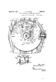
- Figure l is a face view ofthe device, with portions successively broken away for the clear representation of the cooperation of the elements.
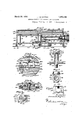
- Fig. 2 is a section substantially on a diametral plane through the staff and the reset shaft of the device according to Fig. l.
- Fig. 3 is a face View of the compensating mechanism.
- Fig. 5 is a fragmentary section of a detail of the sealing structure.
- Fig. 6 is a diametral section of the hand staff and friction clutch.
- Fig. 7 is a view in section through the resetting shaft, showing the resetting cam and the cooperating parts of the hand staff and sleeve.
- Fig. 8 is a further section through the resetting lrnob, showing the knob return mechanism and stop for the resetting mechanism.
- Fig. 9 is a sectional View corresponding to Fig. 5, but showing the guard shield.
- the counting device has the base l0 having the cylindrical section ll and the outwardly extending flange 12.
- the flange l2 is provided with the holes 13 to permit securing this base plate to a suitable support.
- the base plate portion 10 receives the elements of the transmitting train, the compensating mechanism, l the counting mechanism, the dial and hand system, .and thereset mechanism. ,e Y
- A.- ,deck plate 14 is heldin parallel spaced relationship to the base plate 10 by-'means of the three pillars 15 which have reduced ends to pass throughaperturesf in the deck plate and the base platecthe kends of these pillars extending throughthe deck plate 14 are upset to form the. rivet heads 15a, soV that the pillars are held immovably with re-L ⁇ gard to the deck lplate,.whereby an unauthor- 1 ized personjls unable toy separate the deck plate 14 from thek pillars 15.r ⁇ Ati the other end the pillars y15 extend through their respective apertures -in the base .plate 10 and are held bythe nuts 15b asV shown in Fig. 2.
- the length of-the reduced 'portion ofthe pillars which extend through the base plate 10 is such thatwhen a single nut- 1522 is locked in position as by a sealing wire 16 and the lead seal 16a, it is indices for unit ⁇ gallons have been sub-Y divided into halves andquarters. ⁇ Playing over this dial and cooperating with the indices is theL pointer or hand 20 which is. se-
- dial 17 ismounted above and rigidly con-V nected to the deck plate 14 by means of the screws which pass thr-ough the spacer collars ⁇ 17?) as shown in Fig. 2whereby they dial, hand, deck plate, and base nplate ymay be assembled and handled as a unit.v
- the gear train is driven ⁇ in any suitable manner, for example, that showngin;v my copending application: whereby it 'will' be understood that the gear 34 is driven as an idler to communicate the driving movement to the gear ⁇ 36.
- This driving movement may,
- TheL strap 32 is to support and guide certain of the'shafts of the Ydriving train, including the shaft4 of the idler gear 34. It will be understood that regatta rigiaiy to; the *i base plate 10 by suitable screws, and serves the ratios of numbers of teeth in the driving train is calculated so that the alternate drive of the indicating ⁇ hand 20 and of the counting mechanism to be hereinafter described, as well as the audible indicator, are propor' tionate to the movementsof the pump; The method of accomplishing this has been indicated in my copending application, Vand is.;
- a further spindle 35 is iixedly mounted on the base plate 10 and extends upwardly therefrom to support the gear 36 which is in mesh with the idler 34.
- the gear 36 is iXedly connected with a driving pinion 37 on its own spindle.
- This drivingpinion 37 in turn isin mesh with the driver plate gear 38 of the compensating device, as shown in Figsif3 and 4, and which will be described more fully hereinafter;
- the compensating mechanism delivers itsmovement to a corrector plate pinion 39 which is likewise indicated in do'ttedV lines YVin Hig.v 1.
- This pinion 39 is in mesh with an idler gear 40 which is carried on a spindle 40a fixed in the base plate 10, and in turn is in mesh with the foot gear 41 of the hand-staff g and thev foot gear 41 is in turn in driving relationship with the first gear 42 'off the counting train.
- ⁇ mounted directly on a shaft 42a which is piv# oted preferably in they plates 43 of the count- This counting ⁇ gear is ,y
- the shaft 42a carries the i dialV which has the successive indicia thereon which display through the respective open-j. ings-43a of the upper plate 43, so that the total number of gallons deliveredmay be read from the indications beneath the respec-r tive windows 43a.
- any appropriate type of transfer mechanism' may ybeemployed to transmit a full rotationy ofthe shaft 42a as a one-tenth rotation of the succeeding shaft, etc., whereby the counting mechanism is actuated.
- Such devices are very ol'dcand well knownlin the art, and the specific assemblypforms no portion of this invention, and need not'be more fully described;
- the counting mechanism is fastened by its plates 43 in some suitable manner to the base 10 so as to be held in fixed position thereon.
- the foot gear 41 is rigidly secured as by peening to a sleeve 44(Fig. 6) which is journaled for loose rotation on the steel spindle 45 which has a spacer collar 46 and a threaded portion 46a at its rear end for engagement in the base plate l0.
- a suitable nut 46d F ig. 2) is employed to lock this spindle 45 in its position.
- a leather friction disk 47 is placed loosely about the sleeve 44 and upon the front face of the foot gear 4l.
- Acounter Vfriction plate 48 is secured to the hand sleeve 49 in any suitable manner, so that it is held parallel to v bore.
- a bushing 52 is inserted between the hand sleeve 49 and the inner sleeve 44 and substantially fills this space, while affording the hand sleeve 49 a front bearing for its rotational movement with respect to the inner sleeve 44. It is preferred to internally chamfer the bushing 52 and to upset the front endV of the inner sleeve 44, whereby the sleeve 44 and the bushing 52 are held solidly together and form the frontreacting member for the L coil spring 51, which thus is contained within an annular cavity formed by the integral hand sleeve 49 and the solidly connected inner sleeve 44 and its bushing 52.
- a knurled ring 53 having rearwardly directed knurls is secured to the bottom of an outwardly extending shoulder of the head 50, and is held in such position and against rotation with respect to this head by means of pins 53a,
- An annular stop bushing 54 is seated about the front end of the steel spindle 45, and is locked theretoby a transverse pin 54a which is passed through the pin slot 54h of the head 50, so that the pin 540J may be passed through the head 50 and the latter have a relative axial movement with respect to the spindle 45 and the sleeve 44.
- the hand sleeve 49 extends away from the base plate 10 and has an enneedles ⁇ under great strain, and imposes no undue friction upon the driving train while counting and indicating is occurring.
- a flat spring 41a exerts a constant drag on the gears and Y prevents the development of back lash by hammering the device.
- the reset mechanism for restoring the hand 20 from itsactuated position to the zero position includes the knob 55 which projects to the exterior of the casing, and is mounted on a threaded stub 56 which is in threaded relationship with the spindle 57 which in turn carries at its inner end the reset disk 58 4(Fig. 7), which is knurled on its periphery and has 'a flattened portion 58a at the portion which is opposite the knurled ring 53 on the hand staff, so that this knurled ring, when the reset mechanism is in its inoperative position, is free ofthe knurled ring 53, and the latter isenabled to turn without any friction being placed upon it from the resetting mechanism.
- the spindle 57 is guided in a sleeve 59 of a stirrup 60 Vfixed to the base plate 10.
- a non-return device is provided for the spindle 57 toV prevent a reverse movement thereof and to require its full revolution when ide pin66 of the dogand engages'its ends against pins 69 on the dog and 68 on the strap 60.
- a screw-*63a holds the core61 fixed. to the spindle 57 while a pad 65 holds the clutch plate against rotation.
- the compensating mechanism is constructed as follows: a driver plate ⁇ 80 and a corrector plate 81'are held fixedly in spaced re-v lationship with regard to each other by spacer pil-lars 82 and screws passing therethrough.
- Located between ⁇ these Vcorrector plates are two corrector clutch rings 83 and 84, ⁇ which are formed with circular central apertures with notches olfset therein to receive the clutch balls 83a which cooperate with springs to force the balls into wedging relationship between the respectiveplates 83,84 and the .i central core 85.
- the notches on each of the plates 83, 84 are directed similarly, so that one of these clutch plates with its balls! and springs will move relatively to the clutch core while the other holds it, and vice versa.
- Vthese compensator clutch rings is necessary to secure an easy-operation ⁇ of the clutch and an actuation of the corresponding amount throughout the mechar ⁇ nism, and this represents a very minute'percentage of'a usual delivery.
- VThe driver plate gear 38 is secured tothe driver plate 80 for movement therewith at al1 times.
- a 4clutch core 85 of hardenedsteel is mounted y'coaxially with the driver and corrector plates for movement with relation thereto, and ex-- tends through'the two corrector clutch rings 83. 84 and comes approximatelyto the in-VK ner face of the driver plate.
- a spacing ring 86 is located between the twocorrector clutch rings for the purpose of keeping theballs 83a and their associated springs Y within the ed on the adjuster screw 91.”y
- This adjuster screw 9i is freely rotatable in the'corrector lever 92 which has upstanding-ends to'form journal bearings for the screw91.
- the screw 91 has a head'91a at itsendadjacent the periphery of the corrector yplate 8l..
- the correctorplate 8l is provided with two slots V81a and 816 through its face.
- the pivot pin 93 ofthecorrector lever 92 is'fixedly mounted in the upper clutchring 83, which likewise hasjthe post 94 upstanding therefrom through the aperture 81?), with Va reduced stop at,V its upper end to receive the link 94a which is held thereon by a pin 94?): post 95 secured to the corrector plate-81 serves as aV guide for the helical portion of a take-up spring 96, one arm of which engages infan aperture in the free end of the link 94a and the other end of which is secured beneath' a reaction screw97 whichholds it iixedly to they corrector plate'.
- ThisV take-up spring tends at all times 'to pull the clutch A.ring 83 counterclockwise withl regard to ⁇ the corrector plate 81, and thus im-V poses a constant take-up upon the entiresystem, andy prevents any back-lash occurring at the beginning or ending of the registering movements.
- a toggle break spring 98 may be connected by a post 98a on the corrector plate 81, and a screw 98?) onthe guide link 88; but this is not essential and is only employed in cases where the adjustment of the traveling ⁇ nut 90 along the screw 91 may bring it to a position whereby,jduring the movement ⁇ of the corrector lever 92, the centers of the pivots 93, 89 and 87 may extend in a straight line.
- a post 101 ex. tends Y .downwardly from the deck plate through this cam and through a spacer 102,r and passes through a post hole 10111 through the corrector to the compensating mechanism.
- The. axially directed end of the corrector leverV 92 is provided with a cam dog 92a which rests against the periphery of the cam 100.
- the cam 100 has been shown in dotted lines yin thisl figure, and it is seen that this clockwise excess rotation ofjthe corrector ⁇ clutch ring 83 is accomplished during a clockwise rotation of the corrector plate 81 itself During this movement, the take-up spring 96 yields slightly, but at all times prevents any slaokness or back-lash between the re- ⁇ spective members; and at the moment/that the cam dog 92a slips down the radial por- ⁇ tion of the cam 100, the'take-up spring96 immedately snaps or jerks the corrector yclutc-h ring 83 back toits original position with respect to the corrector plate 81.
- the amount of the relative advance of the corrector clutch ring 83 with respect to the corrector plate 81 is uniform throughout a rotation of the corrector plate 81, since the cam 100 is of constant and uniform rise. It will further be seen that the actual amount of this advance during a single revolution depends upon theratio of the lever arms from th-e engaging point of the cam dog 92a; to the effective center of the traveling nut 90. in proportion to the distance from the elective center of the traveling nut 90 tothe pivot 93. ⁇ It will be understood that the effective center of the traveling nut 90 depends upon the sizes and separations of the respective members, including the traveling nut 90, the pivot 89, the guide link 88 and the pivot 87.
- a counterweight' 10a which is fastened by a screw 105 disposed eccentrically in its mass to the corrector plate 81.
- the unbalanced mass of the corrector mechanism including the corrector lever 92, the traveling nut 90, and the guide link 88 and other. members, is compensated by ⁇ balancing, the compensating mechanism about its axis by slipping the counterweight 104 around beneath its screw 105 when the latter is slightly loose. The counterweight is then tightened into position, and it is no longer possible to secure a fraudulent change of the mechanism by jarring.
- the clutch core 85 is provided with a tubular sleeve 85a which passes through the driver plate 8O and its driver plate gear 38 and is provided with the pinion 39 which is fixed to thisy sleeve 85a in some suitable manner. as b y peening.
- a casing is provided around the whole. It is preferred to form the base plate 10 by stamping from sheet material such as steel, wherebv to form the setting fiange 12, the barrel fiange 11 and the base ⁇ plate proper 10.
- the casing 110 is likewise preferably formed of sheet material formation, into shape to have a slight outward enlargement 111 at the base adjacent the barrel flange 11,V so that the cork packing ring 112 may be cemented into position in this enlargement, so that when the casing 110 is seated upon the barrel flange 11, a dust and water-tight joint is formed.
- the casing 110 is provided with a protective rolled bead 113 which terminates with an inward flange 114 which serves as a seat for theglass pane 115.
- putty is placed in the bead 113 and the glass pane 115 is placed into position and forced home until the putty is extruded around the edges of the pane of glass, as shown, whereby a resilient and tight seating is provided for the pane of glass, and all entry of dust and water into the casing at this point is prevented.
- the putty is then scraped away substantially flush with the glass pane 115 ⁇ and a small felt ring 116 is placed in position at the periphery of the glass, and held in position by a split metal ring 117 :Vv this felt ring and the split ring being received withi-nl a ,shallow groovey in.
- the gap between the ⁇ deck plate 14 and the cover plate 10 is closed-by the two bands 120 and 121 (FigsJl and 5).
- the band 121vis provided with an eye.12 2 which receives the hook 123 on the bandr120,
- the.y yguard band 121 is providedatone edge -fwith ⁇ v ⁇ against separation.
- An aperture is provided in the base rplate 10 ⁇ and is in line with the. threaded'hole inthe lock lug 124 when .the guard bands 120, 121 are iny position, as shown in Fig.y 5: anda sealing ⁇ y screw 127 may be passed through the aperture of the base plate 10 andk into the threaded hole of the lug ⁇ 124 and; awire 16Kfor vpassing through the head of the screw 1 27Qand c through the pillar 15.V beneath thelofckfnut 15b, so that the two bandsV are heldimmovably -in position.
- the adjusting holes are alined; and further more'a downwardly extending adjustment shield .129,- isY secured to the deck plate 14 and. has itself an adjusting hole, which is in alinement withk the 'adjusting holes in the bands 120, 121 nnder the conditions specified.
- the cam 1.00 is so disposed with-regard tov the direction of its radial portion that. when-the cam Ydog 92a of the correcting lever 92 has just slipped down the radial face .of this cam 100, the head 91a on the adjuster ,screw ⁇ 91 is presented in alinementfwitli the several ⁇ yad-- justing holes. Only undertheseconditions may a screw-driver b-e introduced through these holes to gam ⁇ access to the adjusting;
- the audible indicator isactuatedfrom the countercfriction plate 48 which forthis pur- ⁇ pose isformed at its per-ipherywith'twenty teeth, corresponding ⁇ to theY 20 gallons of V'maximum indication by the Vhand 20 on ythe dial'17. .
- a rocker 20 ⁇ 0 is pivoted on a Pin 201,. fixed.
- the rocker 200 andits spring arm 202i are contained withinthe rsealing bands 120, 121.”v c At itsV other end the rocker 200 is provided with a pivot 207 .forl a dogf208 rwhich presents one end in the. path oftheteethyon the friction plate 48, and which is vpreventedfrom counterclockwise movement by these teethj by an upstandinglug 209 onV the rocker 20.0.T
- a return spring 210 is connected to the other end of the dog and to therocker 200to hold the-,dog against the lug209 at all times.
- the normal ratio of drive from the driving member 'to the compensator involved a movement of about '2.625 revolut-ions for onegallon as the theoretically exact angular distance of rotation for correct totalizing registration: and inthe device itselt', theinitial gear rat-io without any compensation was 2.685, or a loss ,of about 2%in the angular distance of rotation.
- this compensation ma vAs the clutch plate 88 is moved forwardly with regard to the plate 81, it drives the clutch core 85 by the amount of its'own angular movement, so that'his clutch core 85 moves faster in rotation than the driver gear 38, and hence the pinon 39 moves at a greater angular speed: and the amount of this increase in angular speed is determined by the position of the traveling nut 90 on the spindle 91, as heretofore described.
- the gear trains and individual gears are ment of the pump handle ⁇ 'which is to be totalized, and according to the ratio oic move ⁇ ment of thepump handle with regard to the indicating ⁇ hand and totalizer changes ot the gears 34.-, 86, 37, 88 and39, will permitthe registration of volumes by gallons or litres or any other unit with a gong rachet and counting 'mechanism lIt it bedesired to change the number of iigureson the indicating dial, a-
- the hand 20 has completed a movement to indicate eighteen and one-half gallons,v and the tooth 212 of the friction plate i8 is shown as having forced the dog ⁇ 208 to move the rocker 200 by about half of its movement.
- TheV device maybe monntedf'upon a discl pensing pump, forv example,r by means ⁇ of screws passing throughv aperture 130i the iiange l2. e y. y A It will be.understoodthatthroughout this descriptionand ⁇ inthe accompanying claims pulses from the driver member. e
- a device ofthe character described including areciprocating piston pump heving 4a limited volume of delivery kat each stroke anioscillatable shaft connected to move with the pump piston, the combination of a gonmngong sounding deviccfan inter ⁇ i inittcnt ⁇ movementpclutch connect-ed to said shaft, and agen-trein driven always inthe seme direction hyisaid shaft through said:r clutch forimoving seid sounding devices said Y t Y train including e compensating mechanism for varying the ratio of transmission from lseid clutchftosaid sounding dcvicehy a reguletnble traction thercof- Y I 3.. lin a dcviceoi he character described,
- a reciprocating Piston pump havA- ing a limited volume of delivery-et each stroke and .en oscillatable shaft connected to move With the pump pistomv the combination of c' gong, n .gong soundingv device,y en inter-Y mittent movement clutch connected to scid shaftand a gear train driven alwaysfin the seme direction by said .shaft through said clutch formoving-seid sounding dev-icc, said 'f train including a compensating mechanism comprising .two coaXinlsnd relatively rotstsblc gears included insaid gear train, a
- said gong sounding device cooperating with said ratchet whereby to ⁇ sound the gong once for each tooth of said ratchet during movement of theratchet when driven by said member, andperinitting the ratchet to return freely without sounding of Vthe gong in the opposite direction of movement, spring means to move saidv ratchet iii said other direction to avzero position, and a resetting mechanism for separating said ratchet from said friction surface whereby to permit the ratchet to be returned to the zero position and thereafter operating to restore said ratchet wheel to engagement with said member.
- a device of the character described including a reciprocating piston pump having a limited volume of delivery at each stroke and an oscillatableshaft connected to move with the pump piston, the combination of a gong, a gong sounding device, an intermittent movement clutch connected to said shaft, and a gear train driven always in the Vsame direction by said shaft through said clutch for moving said sounding device, said train including a driving member andl a ratchet wheel adapted to engage said member to be driven thereby when in one position and to be free of said member when in another position, said ratchet wheel actuating ksaid sounding device once for each tooth of vsaid ratchet, means to return the ratchet wheel into a Zero position when disengaged from said member, a stop to limit the restoring movement of said returning means upon said ratchet, and a resetting mechanismV to separate said ratchet from said member and thereafter to impart to said ratchet an energization in excess of that required to restore said ratchet
- a device of the character described including a reciprocating piston pump having a limited volume of delivery at each stroke in an oscillatable shaft connected toV move'with the pump piston, the combination of a. gong, a gong sounding device, an intermittent movement clutch connected to said ,shaft, and a 'gear train driven always in the same direction by said, shaft through said clutch for movingsaid sounding device, said train including two relatively movable mem- "bers, one of said members being driven by ameter of cylinder and in length of stroke for deliveryrof a standard volume, a gong, a sounding device for said gong, a gear Vtrain driven with said pump, and a compensating device connected to said gear train-andincluding adjustment means whereby the movement of the final .element of said train may be varied by a desired fraction of the movement ratio determined by said train, so that the device may be sounded at the delivery of integral units of volume by any of said pumps to which it may be. connected and adjusted.
- a signal device for liquid dispensing pumps which vary one from another by di-V ameter of cylinder and in length of stroke for deliverybf a standard volume, a gong, a ratchet wheel, a sounding device for said gong actuated bysaid ratchet wheel once for every tooth thereof, a gear train driven with said pump and including a compensator having an adjustment meanswhereby said ratchet wheel is advanced by one tooth for the de livery of a unit volume by one of said pumps, said compensator modifying the movement of said train at a'ratio according to said adjustment which corresponds to the variation of the particular pump rfrom standard.
- V l0 V l0.
Landscapes
- Physics & Mathematics (AREA)
- Fluid Mechanics (AREA)
- General Physics & Mathematics (AREA)
- Reciprocating Pumps (AREA)
Description
March 22, 1932.
J. M. DAYTON AUDIBLE COUNTING AND COMPENSATING MECHANISM Original Filed May 14, 1927 2 Sheets-Sheet l March 22, 1932. 1,8 50
AUDIBLE COUNTING AND coMPENsAUNG MEcHANIsM J. M, DAYTON Original Filed May 14. 1927 2 Sheets-Sheefl 2 Leu5;
Patented Mar. 22, 1932 JAMES M. DAYTON, OF T'ORRING'TON, CONNECTICUT AUDIBLE COUNTING AND COMPENSATING MECHANISM Application filed May 14, 1927, Serial No. 191,368. Renewed Februaiy 2, 1932.
This invention relates to improvements in audible mechanisms for counting and for compensating constantly recurring errors in transmitting systems.
A compensating device of this type has already been disclosed by my application Serial No. 167,799, iiled Feb. 12, 1927,' on counting and compensating mechanism to Which reference is made for certain features of a device of this type Which are not fully disclosed herein. For ease of comparison, like reference numerals have been employed in the tvvo applications. Such devices are more particularly intended for employment in compensating the movement of a dispensing pump piston as transmitted to and measured by a counting mechanism, as for example in the counting ofthe total number of gallons dispensed by a gasoline filling station pump and in particular according to the present application, an audible indication is delivered at the completion of the delivery of each unit of volume, e. g., each gallon. It Will be understood, however, that the invention is not limited to such employment but is described hereinafter by Way of example in connection with such a dispensing pump, although it Will find employment in many arts.
It is Well known that reciprocating gasoline dispensing pumps employ cylinders and pistons made of dravvn tubing, and in consequence of differences arising during the course of fabrication, such cylinders and their pistons are not all of the same diameter, whereby it becomes necessary to vary the effective stroke of the piston in order to produce the dispensing of a normal or standard quantity, as for example, one gallon. Since it is desirable to measure the dispensing not only of the full or unit quantity of one gallon with such a pump, but also the most minute fraction thereof, it has been found as pointed out in my aforesaid patent application, that it is necessary to employ some compensating or correcting device between the pump actuating device and the counting mechanism, whereby such differences may be compensated for, or corrected, and even the smallest fraction of a unit volume be totalized by the counting mechanism. If, for example, the
owner of the pump should place it in chargek of a custodian, it is desirable that the owner of the pump should have an accurate check upon the total number of gallons Which have been dispensed therethrough, since this is a. measure of the money which should be turned over by the custodian to the ovvner. It is found essential that the custodian should not be able to defraud either the customer or the owner by, on the one hand, dispensing the liquid Without causing an actuation of the kcounting mechanism: and on the other hand,
by making claim to the customer for a quantity of gasoline which has not been fully delivered to him. F or such reason, it is essential that the pump should at all times be positively connected to the counting mechanism, and that the compensator should be of a type which Will respond to even the smallest movement of the pump handle.
For this purpose and according to the present invention, a positive train of gears is employed to connect the pump shaft through a driver member with the counting` mechanism and a compensating device is included in this gear train to establish automatically, continuously and regularly the necessary correction for the variation of the particular pump cylinder from the normal or standard. To this end, the movements of the driver member in one direction are caused to be summed, While the movements of the driver member in the other direction are free and Without eiiect upon the counting mechanism. In this Way, the movement of the gear train is continuously in one direction, and no variation or error comes into existence by reason of back-lash in the gears, provided there either for constructional reasons of ease of movement or arising by reason of Wear of the several parts. The compensating device included in this gear train comprises two members, one of which is driven positively from the driver member and the other of Which is driven from the said first member ofthe compensator device, but With a constant excess or advance movement over the motion of the said {irst member arising by reason of its drive from said driver member. The compensating device is particularly characterized by reason of the fact that it moves continuously in rotation, and is therefore competent and required to establish such compensation or correction throughout the 360 of its rotation, and thereafter to reset for compensation through a further 860, etc.
Further, in connection with this invention there is employed an indicating hand and an audible indicator whereby the customer is enabled to observe and hear the indication of the quantity of gasoline which is being delivered to him, and by reason of the employment of the compensating device in the driving train for such hand and indicator, the indications are calibrated and compensated so that a correct indication is given by the hand and audible indicator, regardless of the diameter or structures of the particular pump. Means are provided for resetting this hand to its initial or zero position, and these means are irovided entirely independently of the connection of the counting mechanism through its train to the driver member, so that if the indicating` hand be even in the process of the return movement when the pump is actuated, yet the totalizing counting mechanism will receive its due movement as a safeguard to the owner of the pump. Furthermore, during this return movement, the audible indicator is likewise severed from its relationship with the driver train. so that at all times the audible indicator operates to notify the customer in exact consonance and synchronism with the movement of the indicating hand. It is further provided that during the normal movement of the hand and the moving parts of the audible indicator in dispensing the liquid, these parts shall be free from engagement with the resetting' mechanism, whereby the eiort necessary for the actuation of the counting and indicating` systems is reduced to a minimum: and on the other hand, the resetting mechanism is so disposed that during the operation of resetting, the hand and indicator and their associated parts are removedfrom subj stantial frictional engagement with the counting mechanism and its driving system, whereby the creation of back-lash or undesired movements in any member of this system, or a frictional contact with any member of this system for erroneous and wrongful operation, is rendered impossible.
As in my copending application, means are provided for enclosing and guarding the essential moving elements of the apparatus against water and dirt, so that they are protected from excessive wear and errors arising therefrom. A sealing system is further provided whereby the adjustments of the compensating elements are made accessible only to a properly authorized person, and it is possible to determine at all times whether any attempt has been made to modify the compensator.
The audible indicator according to the present invention is located on the exterior of the journal casing so that its noise is clearly perceptible to the customer: but at the same time the moving parts are all protected within the aforesaid seal.
As in my former application, the moving elements are counterbalanced so that no undesired operation of the driving train, the counting mechanism, and the indicators may be accomplished by aid of hammering upon the casing: and the various parts are assembled in units so far as possible.
` The reset mechanism employed for the hand according to my copending application is employed in the present instance to reset the audible indicator, and this mechanism cannot be returned without completing afull strolre, so that it is impossible for the custodian of the pump to defraud a customer by leaving the indicating hand at a higher reading than the zero position at the beginning of a delivery or to leave the audible indicator elements in such position that the gong is sounded sooner than at the completion of the delivery of a full gallon. lith these and other objects in view as will appear in the course of the following specification and claims, taken in conjunction with the accompanying drawings, there is shown in the latter an illustrative form of execution and application of this invention in its employment with a gasoline dispensing pump of any suitable type.
In these drawings:
Figure l is a face view ofthe device, with portions successively broken away for the clear representation of the cooperation of the elements.
Fig. 2 is a section substantially on a diametral plane through the staff and the reset shaft of the device according to Fig. l.
Fig. 3 is a face View of the compensating mechanism.
- Fie". 4 is a diametral section through the compensating mechanism in position on the deck plate.
Fig. 5 is a fragmentary section of a detail of the sealing structure.
Fig. 6 is a diametral section of the hand staff and friction clutch.
Fig. 7 is a view in section through the resetting shaft, showing the resetting cam and the cooperating parts of the hand staff and sleeve. V
Fig. 8 is a further section through the resetting lrnob, showing the knob return mechanism and stop for the resetting mechanism.
Fig. 9 is a sectional View corresponding to Fig. 5, but showing the guard shield.
In these drawings, the counting device has the base l0 having the cylindrical section ll and the outwardly extending flange 12. The flange l2 is provided with the holes 13 to permit securing this base plate to a suitable support. The base plate portion 10 receives the elements of the transmitting train, the compensating mechanism, l the counting mechanism, the dial and hand system, .and thereset mechanism. ,e Y
A.- ,deck plate 14 is heldin parallel spaced relationship to the base plate 10 by-'means of the three pillars 15 which have reduced ends to pass throughaperturesf in the deck plate and the base platecthe kends of these pillars extending throughthe deck plate 14 are upset to form the. rivet heads 15a, soV that the pillars are held immovably with re-L` gard to the deck lplate,.whereby an unauthor- 1 ized personjls unable toy separate the deck plate 14 from thek pillars 15.r` Ati the other end the pillars y15 extend through their respective apertures -in the base .plate 10 and are held bythe nuts 15b asV shown in Fig. 2.
It will be understood that the length of-the reduced 'portion ofthe pillars which extend through the base plate 10 is such thatwhen a single nut- 1522 is locked in position as by a sealing wire 16 and the lead seal 16a, it is indices for unit` gallons have been sub-Y divided into halves andquarters. `Playing over this dial and cooperating with the indices is theL pointer or hand 20 which is. se-
cured to a central shaft and iactuated in the.
manner tobe described hereinafter. The
l.The gear train is driven `in any suitable manner, for example, that showngin;v my copending application: whereby it 'will' be understood that the gear 34 is driven as an idler to communicate the driving movement to the gear `36. This driving movement may,
for example, Ybe accomplishedby the oscillation of a shaft by thepump handle-while the pump is being actuated, so thatthegear 34 follows exactly allmovements of the pump:
and an intermittent clutch 23 is provided inV the driving train (Fig. 2). so that the move* ments of the driving element in one direction by meansof the clutch cause the driving of the gear 34 in this direction andbyaproportionate amount no matter how `smallmay be the movement in such rdi.re t 1r1fwhile 0n the other hand, aI'novement of lthe driving member inthe opposite direction is without effect upon the gear 34which remains stationary during such reverse movement. It will be understood that by this means the delivering or ,the returning movement of the pump handle is caused to actuate the gear 34 incnedirectionand not in the other, so
that .the movements of the gear 34represent the-actual delivery from the pump. g Such a driving train has been described and more completely` illustrated in my copending app iication, and is not claimed herein except insofar as it constitutes a part of the driving system. Y
TheL strap 32 is to support and guide certain of the'shafts of the Ydriving train, including the shaft4 of the idler gear 34. It will be understood that regatta rigiaiy to; the *i base plate 10 by suitable screws, and serves the ratios of numbers of teeth in the driving train is calculated so that the alternate drive of the indicating `hand 20 and of the counting mechanism to be hereinafter described, as well as the audible indicator, are propor' tionate to the movementsof the pump; The method of accomplishing this has been indicated in my copending application, Vand is.;
generally within the ability of a mechanic. A further spindle 35 is iixedly mounted on the base plate 10 and extends upwardly therefrom to support the gear 36 which is in mesh with the idler 34. The gear 36 is iXedly connected with a driving pinion 37 on its own spindle. This drivingpinion 37 in turn isin mesh with the driver plate gear 38 of the compensating device, as shown in Figsif3 and 4, and which will be described more fully hereinafter; The compensating mechanism delivers itsmovement to a corrector plate pinion 39 which is likewise indicated in do'ttedV lines YVin Hig.v 1. This pinion 39 is in mesh with an idler gear 40 which is carried on a spindle 40a fixed in the base plate 10, and in turn is in mesh with the foot gear 41 of the hand-staff g and thev foot gear 41 is in turn in driving relationship with the first gear 42 'off the counting train.` mounted directly on a shaft 42a which is piv# oted preferably in they plates 43 of the count- This counting `gear is ,y
ing mechanism. The shaft 42a carries the i dialV which has the successive indicia thereon which display through the respective open-j. ings-43a of the upper plate 43, so that the total number of gallons deliveredmay be read from the indications beneath the respec-r tive windows 43a. It willbe understood that any appropriate type of transfer mechanism' may ybeemployed to transmit a full rotationy ofthe shaft 42a as a one-tenth rotation of the succeeding shaft, etc., whereby the counting mechanism is actuated. Such devices are very ol'dcand well knownlin the art, and the specific assemblypforms no portion of this invention, and need not'be more fully described;
Vthe foot gear 4l.
herein. The counting mechanism is fastened by its plates 43 in some suitable manner to the base 10 so as to be held in fixed position thereon. Y f
The foot gear 41 is rigidly secured as by peening to a sleeve 44(Fig. 6) which is journaled for loose rotation on the steel spindle 45 which has a spacer collar 46 and a threaded portion 46a at its rear end for engagement in the base plate l0. A suitable nut 46d F ig. 2) is employed to lock this spindle 45 in its position. A leather friction disk 47 is placed loosely about the sleeve 44 and upon the front face of the foot gear 4l. Acounter Vfriction plate 48 is secured to the hand sleeve 49 in any suitable manner, so that it is held parallel to v bore. Y A bushing 52 is inserted between the hand sleeve 49 and the inner sleeve 44 and substantially fills this space, while affording the hand sleeve 49 a front bearing for its rotational movement with respect to the inner sleeve 44. It is preferred to internally chamfer the bushing 52 and to upset the front endV of the inner sleeve 44, whereby the sleeve 44 and the bushing 52 are held solidly together and form the frontreacting member for the L coil spring 51, which thus is contained within an annular cavity formed by the integral hand sleeve 49 and the solidly connected inner sleeve 44 and its bushing 52. A knurled ring 53 having rearwardly directed knurls is secured to the bottom of an outwardly extending shoulder of the head 50, and is held in such position and against rotation with respect to this head by means of pins 53a, An annular stop bushing 54 is seated about the front end of the steel spindle 45, and is locked theretoby a transverse pin 54a which is passed through the pin slot 54h of the head 50, so that the pin 540J may be passed through the head 50 and the latter have a relative axial movement with respect to the spindle 45 and the sleeve 44. It will thus be seen that the foot gear, friction leather disc, the two sleeves, the frontbushing 52, and the knurled ring 53 are assembled as a unit, and when the friction plate is moved toward the front, they rest freely between the collar 46 and the bushing 54 the 'collar 46 of the spindle 45, so that no strain is placed upon this spindle, and even the driving strain of the meshing gears V occurs veryclose to the base plate l0, and
The hand sleeve 49 extends away from the base plate 10 and has an enneedles `under great strain, and imposes no undue friction upon the driving train while counting and indicating is occurring. A flat spring 41a exerts a constant drag on the gears and Y prevents the development of back lash by hammering the device.
The reset mechanism for restoring the hand 20 from itsactuated position to the zero position includes the knob 55 which projects to the exterior of the casing, and is mounted on a threaded stub 56 which is in threaded relationship with the spindle 57 which in turn carries at its inner end the reset disk 58 4(Fig. 7), which is knurled on its periphery and has 'a flattened portion 58a at the portion which is opposite the knurled ring 53 on the hand staff, so that this knurled ring, when the reset mechanism is in its inoperative position, is free ofthe knurled ring 53, and the latter isenabled to turn without any friction being placed upon it from the resetting mechanism. As soon as the knurled disk 58 is rotated by means of the knob 55 and the shaft 57, the attened portion is removed from opposite the knurled ring 53, and the circular portion of the disk 58 is brought into engagement withthe ring 53, whereby the latter is forced toward the front, and in turn raises the hand sleeve 49 against the action of the coil springl, and thereby disengages the friction plate 48 from the leather 47, so that very little or'no frictional resistance is offered by the foot gear 41 to the free movement of the hand sleeve 49. As the friction plate 48 is lmoved away from the foot gear 4l, the front end of the sleeve 44 and its bushing 52 are Vbrought into contact with the stop bushing 54 on the spindle 45, whereby a slight friction is provided, and at the same time the parts are prevented from separating. After the knurled disk 5 8 has completed a full revolution, the flattened portion 58a again comes opposite t-he knurled ring 53, and the latter is moved toward the rear so that the friction plate 48 is again brought into Contact with Vthe leather 47 and thus with the foot gear 4l.,
for frictional driving as before: and likewise the knurled ring 53 is finally left free of the knurled diskV 58, so that again no frictional relationship existsfbetween the two.
The spindle 57 is guided in a sleeve 59 of a stirrup 60 Vfixed to the base plate 10.
A non-return device is provided for the spindle 57 toV prevent a reverse movement thereof and to require its full revolution when ide pin66 of the dogand engages'its ends against pins 69 on the dog and 68 on the strap 60. A screw-*63a holds the core61 fixed. to the spindle 57 while a pad 65 holds the clutch plate against rotation.
The compensating mechanism is constructed as follows: a driver plate`80 and a corrector plate 81'are held fixedly in spaced re-v lationship with regard to each other by spacer pil-lars 82 and screws passing therethrough. Located between `these Vcorrector plates are two corrector clutch rings 83 and 84,` which are formed with circular central apertures with notches olfset therein to receive the clutch balls 83a which cooperate with springs to force the balls into wedging relationship between the respectiveplates 83,84 and the .i central core 85. The notches on each of the plates 83, 84 are directed similarly, so that one of these clutch plates with its balls! and springs will move relatively to the clutch core while the other holds it, and vice versa.
These rings 83, 84 have been made largeV inV order to reduce the minimum registrable quantity. It has been found in practice that a .01 of an inch movement in the inner 'pe-.1
riphery of one of Vthese compensator: clutch rings is necessary to secure an easy-operation` of the clutch and an actuation of the corresponding amount throughout the mechar` nism, and this represents a very minute'percentage of'a usual delivery. VThe driver plate gear 38 is secured tothe driver plate 80 for movement therewith at al1 times.- A 4clutch core 85 of hardenedsteel is mounted y'coaxially with the driver and corrector plates for movement with relation thereto, and ex-- tends through'the two corrector clutch rings 83. 84 and comes approximatelyto the in-VK ner face of the driver plate. A spacing ring 86 is located between the twocorrector clutch rings for the purpose of keeping theballs 83a and their associated springs Y within the ed on the adjuster screw 91."y This adjuster screw 9i is freely rotatable in the'corrector lever 92 which has upstanding-ends to'form journal bearings for the screw91. The screw 91 has a head'91a at itsendadjacent the periphery of the corrector yplate 8l.. The correctorplate 8l is provided with two slots V81a and 816 through its face. The pivot pin 93 ofthecorrector lever 92 is'fixedly mounted in the upper clutchring 83, which likewise hasjthe post 94 upstanding therefrom through the aperture 81?), with Va reduced stop at,V its upper end to receive the link 94a which is held thereon by a pin 94?): post 95 secured to the corrector plate-81 serves as aV guide for the helical portion of a take-up spring 96, one arm of which engages infan aperture in the free end of the link 94a and the other end of which is secured beneath' a reaction screw97 whichholds it iixedly to they corrector plate'. ThisV take-up spring tends at all times 'to pull the clutch A.ring 83 counterclockwise withl regard to` the corrector plate 81, and thus im-V poses a constant take-up upon the entiresystem, andy prevents any back-lash occurring at the beginning or ending of the registering movements. A toggle break spring 98 may be connected by a post 98a on the corrector plate 81, and a screw 98?) onthe guide link 88; but this is not essential and is only employed in cases where the adjustment of the traveling` nut 90 along the screw 91 may bring it to a position whereby,jduring the movement `of the corrector lever 92, the centers of the pivots 93, 89 and 87 may extend in a straight line.
On the lower side of the deck plate of constant and equal rise. A post 101 ex. tends Y .downwardly from the deck plate through this cam and through a spacer 102,r and passes through a post hole 10111 through the corrector to the compensating mechanism. The. axially directed end of the corrector leverV 92 is provided with a cam dog 92a which rests against the periphery of the cam 100. l't will bel understood that as the corrector plate 81 is rotated about the axis Yof the post 101, the cam dog is forced outwardlyby this cam G, whereby the corrector lever 92 is caused to rock about pivots 89'and 87 ina compound 1notion,'and its-own pivot centerV 93 and the corrector clutch ring 83 is caused to move slightly clockwise in the yposition of Fig. 3. The cam 100 has been shown in dotted lines yin thisl figure, and it is seen that this clockwise excess rotation ofjthe corrector` clutch ring 83 is accomplished during a clockwise rotation of the corrector plate 81 itself During this movement, the take-up spring 96 yields slightly, but at all times prevents any slaokness or back-lash between the re-` spective members; and at the moment/that the cam dog 92a slips down the radial por-` tion of the cam 100, the'take-up spring96 immedately snaps or jerks the corrector yclutc-h ring 83 back toits original position with respect to the corrector plate 81.
lt will be understood that during the relative clockwise advance of the corrector 14Lis provided a cam 100 which is substantially clutch ring 83 with regard to the corrector plate 81, the clutch ring with its balls and springs is tightlyengaging the clutch core.
and rotating the same. Since this clutchV core is engaged by thecorrector clutch ring 83, it is caused to rotate for a slightly greater angular distance than the actual distance covered by the corrector plate 81 and its coupled driver plate 80 under actuation from the pump handle. The moment, however, that the cam dog slips down the radial face of the cam 100, the corrector clutch ring 83 loses its engagement with the clutch core, by reason of its reversal of movement and the disengagement of the balls and springs, and the corrector clutch ring 83 slips back, as noted, without effective operation of any kind, and under the impulse of the take-upV spring 96.
It, will be seen that the amount of the relative advance of the corrector clutch ring 83 with respect to the corrector plate 81 is uniform throughout a rotation of the corrector plate 81, since the cam 100 is of constant and uniform rise. It will further be seen that the actual amount of this advance during a single revolution depends upon theratio of the lever arms from th-e engaging point of the cam dog 92a; to the effective center of the traveling nut 90. in proportion to the distance from the elective center of the traveling nut 90 tothe pivot 93.` It will be understood that the effective center of the traveling nut 90 depends upon the sizes and separations of the respective members, including the traveling nut 90, the pivot 89, the guide link 88 and the pivot 87. Since the sizes of these members are fixed inthe original construction, it is apparent that by a variation of the position of the traveling nut 90 Y'along the threaded spindle or screw 91,7the lever ratio may be modified, and in particular that as the traveling nut 90 comes closer to the cam dog 92a, a greater' and greater angular distance of movement is afforded to the corrector clutch ring 83, and that on the con-V therewith. During the quick return movement of the corrector clutchv ring 83, when the clutch core is disengaged therefrom, the corrector clutch ring 84 with its own ballsr and springs lock with regard to the clutch core, and prevent any return movement thereof, thus maintaining the excess or `advance movement of the clutch core lwith regard to the corrector and Vdriver plates.
Since a fraudulent operation of the device might possibly be attained by jogging or knocking it with the hand or a hammer handle, it is preferred to employ a counterweight' 10a which is fastened by a screw 105 disposed eccentrically in its mass to the corrector plate 81. The unbalanced mass of the corrector mechanism including the corrector lever 92, the traveling nut 90, and the guide link 88 and other. members, is compensated by` balancing, the compensating mechanism about its axis by slipping the counterweight 104 around beneath its screw 105 when the latter is slightly loose. The counterweight is then tightened into position, and it is no longer possible to secure a fraudulent change of the mechanism by jarring.
The clutch core 85 is provided with a tubular sleeve 85a which passes through the driver plate 8O and its driver plate gear 38 and is provided with the pinion 39 which is fixed to thisy sleeve 85a in some suitable manner. as b y peening.
It will be seen that the driver and corrector plates and the mechanism attached thereto are held fixedly together, so that all these elements may be inserted and removed as a unit, which is generally indicated in F ig. 1
of the drawings by the dotted lines representing the Deripheries of the gear 38, and the pinion 39.
VIn order to enclose and contain these pieces of mechanism, a casing is provided around the whole. It is preferred to form the base plate 10 by stamping from sheet material such as steel, wherebv to form the setting fiange 12, the barrel fiange 11 and the base `plate proper 10. The casing 110 is likewise preferably formed of sheet material formation, into shape to have a slight outward enlargement 111 at the base adjacent the barrel flange 11,V so that the cork packing ring 112 may be cemented into position in this enlargement, so that when the casing 110 is seated upon the barrel flange 11, a dust and water-tight joint is formed. At the other end the casing 110 is provided with a protective rolled bead 113 which terminates with an inward flange 114 which serves as a seat for theglass pane 115. In assembling the device, putty is placed in the bead 113 and the glass pane 115 is placed into position and forced home until the putty is extruded around the edges of the pane of glass, as shown, whereby a resilient and tight seating is provided for the pane of glass, and all entry of dust and water into the casing at this point is prevented. The putty is then scraped away substantially flush with the glass pane 115` and a small felt ring 116 is placed in position at the periphery of the glass, and held in position by a split metal ring 117 :Vv this felt ring and the split ring being received withi-nl a ,shallow groovey in.
Y The point of entryofthefknob stud 55 through the casing 110 isnprotected by-a gland 130 which is held for self-alinementpby pins 141passing through the casingv 110: while a Y water groove 132 is formedon thestub itself.
vIt has already been shown yand described how the deck plate 14 and the base platelOv are held against separation without breakage of a sealing device 16, 16a, Inord-er further. to protect the mechanism from fraudulent readjustment,the gap between the `deck plate 14 and the cover plate 10 is closed-by the two bands 120 and 121 (FigsJl and 5). The band 121vis provided with an eye.12 2 which receives the hook 123 on the bandr120,
so that these ymembers are lockedtogethery At its Aother end the.y yguard band 121 is providedatone edge -fwith`v` against separation.
an adjusting hole and atits. other edge with alock lug 124. The other strap, 120, is pro-y videdat its otherend with an adjustinglhole,
and rwith a notch forthe-lock lug 124. 1 An aperture is provided in the base rplate 10 `and is in line with the. threaded'hole inthe lock lug 124 when .the guard bands 120, 121 are iny position, as shown in Fig.y 5: anda sealing` y screw 127 may be passed through the aperture of the base plate 10 andk into the threaded hole of the lug` 124 and; awire 16Kfor vpassing through the head of the screw 1 27Qand c through the pillar 15.V beneath thelofckfnut 15b, so that the two bandsV are heldimmovably -in position. Insuch position, the adjusting holes are alined; and further more'a downwardly extending adjustment shield .129,- isY secured to the deck plate 14 and. has itself an adjusting hole, which is in alinement withk the 'adjusting holes in the bands 120, 121 nnder the conditions specified. Further, the cam 1.00 is so disposed with-regard tov the direction of its radial portion that. when-the cam Ydog 92a of the correcting lever 92 has just slipped down the radial face .of this cam 100, the head 91a on the adjuster ,screw` 91 is presented in alinementfwitli the several` yad-- justing holes. Only undertheseconditions may a screw-driver b-e introduced through these holes to gam `access to the adjusting;
mechanism for changing the same :k and at all other` points the mechanism isxprotected against accidentaly or intentional change by the aforesaid associated relationshipk of.y the base and deck plates, and by `means-of the4 bands Y120, 121. In orderfurther to prevent. the adjustment or readjustment'of the ad# justerscrews 91 withouty yfirst having broken the seal, 16, 16a, the parts are so arranged that the sealing screw 127 may be threaded fully upward through thel base plate 10,;an'd* the lug .124, whereby its upper end comes op-j posite the adjustingholes 1256, and blocks the same. It willbe noted in Fig. 5 that the Vsealing wire -16 passes through thehead -vof u lthe* sealing screw` 127,V as well as through the `pillar 15: whereby a positive assurance isY afforded against unauthorized modification of the compensating system. A hole in the case ing for thepurpose of adj ustmentis normally cl-osedby the threaded plug110wwhose head tits arecess in the casing 110. i
The audible indicator isactuatedfrom the countercfriction plate 48 which forthis pur-` pose isformed at its per-ipherywith'twenty teeth, corresponding `to theY 20 gallons of V'maximum indication by the Vhand 20 on ythe dial'17. .A rocker 20`0is pivoted on a Pin 201,. fixed. to the `base plate'lO, and carries 'at the upper vend in Fig.; 1 al spring arm 202 whichis bent latl its top kand passes downward through an arcuate slot'203 in the base plate10 :and carries beneath this `base plate and within they cup v'formed by its recessing with regard to the flangeV 12, acl'apper 204. Algong 205 is fastened by'a post 206 tothe ,basey plate 10, and coversthe slot 203 against theinsertionf'of a pin orrother device which might fraudulently beV employed. It will be noted that the rocker. 200 andits spring arm 202i are contained withinthe rsealing bands 120, 121."v c At itsV other end the rocker 200 is provided with a pivot 207 .forl a dogf208 rwhich presents one end in the. path oftheteethyon the friction plate 48, and which is vpreventedfrom counterclockwise movement by these teethj by an upstandinglug 209 onV the rocker 20.0.T
A return spring 210 is connected to the other end of the dog and to therocker 200to hold the-,dog against the lug209 at all times. A
spring211 is connected between the upper end of the rocker 200andv the -base plate V10 and tends at all times to move the rocker 200v in a cloclnvise. direction.` n* p The method of operation ofthis device is as follows: y f f lVhen the pump` is actuated, the actuating handle shaft (not shown) .in known yInanner causes the movement of the driver mem- 'ber 21a and, through the double clutch 23 a movement ofthe gear 34. This occurs in one direction of drive only, for example inA a clockwise direction in vFig.,f1. On the conV trary, when the handle shaftV returnsyit moves freely with the driver vmember 21a" withoutv an actuationofthe gear 34, as has already been described above..v This movement of the idler gear34is transmitted-to the driverfplate gea-r 38,- which being positively connected to the driver and corrector plates 80, 81, causes these plates to move in rotation in a clockwise direction, and by an angular amount which is in exact propor` lash in thiscear train so that even the most t: 7
minute movement is summed up. Asthe'con rector plate 81 rotates about the post101, the corrector lever 92 presents its cam Vdog 92u: against the cam 100 on the deck plate 11i, and asqthe corrector plate moves clockwise in thepos'ition of Fig. 8, this dog 92a is torced successively and uniformly outward by the cam 100. As the lever 92 rocks, it turns about a virtual axis which is determined bythe prevailing position'ot the traveling nut 90, as guided by the link 88 with regard to the pivot 87. s Y
In an actual device which has been constructed and tested, the normal ratio of drive from the driving member 'to the compensator involved a movement of about '2.625 revolut-ions for onegallon as the theoretically exact angular distance of rotation for correct totalizing registration: and inthe device itselt', theinitial gear rat-io without any compensation was 2.685, or a loss ,of about 2%in the angular distance of rotation. This was compensatedV for or corrected by giving the clutch ring 88 a corresponding excess or 1 advance movement with regard to the corbe made as accurate as required.
Y calculated according to the directionof moverectorplate 81 corresponding to this 2% loss. In-the actual device, this placed the traveling` nut 90 about midway of the adjuster screw 91, whereby it was possible rwith this single device to correct for pumps which werel as much as 2% above or below the standard or normal. By'a suitable low pitch of the adjuster screw 91, this compensation ma vAs the clutch plate 88 is moved forwardly with regard to the plate 81, it drives the clutch core 85 by the amount of its'own angular movement, so that'his clutch core 85 moves faster in rotation than the driver gear 38, and hence the pinon 39 moves at a greater angular speed: and the amount of this increase in angular speed is determined by the position of the traveling nut 90 on the spindle 91, as heretofore described.
The gear trains and individual gears are ment of the pump handle `'which is to be totalized, and according to the ratio oic move` ment of thepump handle with regard to the indicating` hand and totalizer changes ot the gears 34.-, 86, 37, 88 and39, will permitthe registration of volumes by gallons or litres or any other unit with a gong rachet and counting 'mechanism lIt it bedesired to change the number of iigureson the indicating dial, a-
1,85o,12s Y .suitable change may be made in the ratios cupies substantially no time. Hence there is no actuation of the clutch core 85 in either direction during the period, and a further safeguard is aorded against such undesired action by the retaining` clutch ring 84: which holds the clutch core in fixed relation to the. driver and corrector plates for this instant. As soon as the dog 92a has again made Contact with the cam 100, this time at its minimum diameter, and a further rotation oi the corrector plate 81 occurs, the lever 91 is forced outwardly as before and causes a Vrenewed precession of the clutch ring 83 with respect to the corrector plate 81.
The counting mechansm and its dials have been advanced until for example nineteen units have been added to its indications: and
likewise the indicating hand 20 has moved 'i until it points to the index 19. During the courseV of this movement ot the indicating hand, the teeth of the friction plate 48 have nineteen times forced downwardtand toward the right against the dog 208, and causedthe rocker 200 tomove countercloclrwise until the tooth passed the dog 208. As soon as the dog escaped from the respective tooth, the rocker 200 was drawn back again in a clockwise direction by the spring 211 and its clapper 204 was drawn by inertia into contact with the gong 205 and produced a single stroke 'for .the respective tooth, with a total ot nineteen strokesjin all. In the position shown in Fig.
1, the hand 20 has completed a movement to indicate eighteen and one-half gallons,v and the tooth 212 of the friction plate i8 is shown as having forced the dog `208 to move the rocker 200 by about half of its movement. It
hand position of the dog 208, the clapper 204 is held slightlyaway from the gong 205: and that this extreme clockwise movement of the rocker 200 is limited by the engagement of the upper end ot' the rocker with 1 by reason of the clutch ring 64: and further,
by reason of the fact that the disk 58 has moved the hand sleeve and parts away from the foot gear 41, it is necessary that the knob will beunderstood that at the extreme lett i teenies,
5.5 betnrned im" a complete-revolution fore the gong and its chipper will again dicate theV number of gallons ,to be delivered to the next customer.v "lhe custodian; there frere is unable te. cheat the eustornerfby fraudulently advancing the gong ratchet ,Without delivery of gasoline, or byrtailing to reset f the ratchet entirelyto` zeroyDuring the returnmovement of the hand 20, andthe gong ratchet, the sleeve 4.9 and .friction plate d8 have been moved totheffront and returned,
i but during this movement the ratchet'tceth.-
on the friction platerlhave caused :the dog '20,8 to rock successively and foreach. of them .in`l a 'clockwise direction about vits pvot 20.7. and against its spring 2107,80, that there is no actuation of the rockerrQOO `during the re.-
turn `or nresetting ofthe hand 20. 1t .Will like'- Wise-be seen that the friction plate 48 and itsteethare'assembled in permanent relation'- ship with the `hand 20, so that if the hand 20 passes a. unit indication on the dial 117,121,
stroke is sounded on the` gong -205 Vand that the friction` plate 48 and its teethmustbe retuinedto zero in order to complete the operation ofthe knob k55, sov as to .restore the parts into the control by the drive train.. If this be nrt done the customer immediately perceives thatV something is Wrong,l since neither thein.- lolicating hand 2O gives him an indicationof the delivery nordoes 'the `gong soundto in` i dicate the even gallons*v f The stop' 71 which limits the return move'- ment of the hand 2O in resetting is supported by a foot 71av screwed to the dial 17, and it.-
se'lf projects above thegpath-of the handQO and out of engagement therewith While the handl is normally Vmoved with: the Y friction plate .48 in its lower Apositiomvbut ybeingin stop relationship with this hand'during-its return path in a higheriplane as a result vo the raising of the sleeve 49 kof the plate48.y
' This has been described inmy copending application, and is referred to only'as indicating that there is a positive. 'stopfcr the'phand 2O and its associatedelements upon resetting,
and. at the same time no drag isgiver to the hand' during its normal movement, so that ytwenty-one ortvventy-two gallons may lbedelivered if the pump be of suchV capacity, Without any greater friction, upon'the hand at the 20 indicationV than at any other.H
TheV device maybe monntedf'upon a discl pensing pump, forv example,r by means `of screws passing throughv aperture 130i the iiange l2. e y. y A It will be.understoodthatthroughout this descriptionand` inthe accompanying claims pulses from the driver member. e
' lt is apparent; thetfthe invention not limited solelyto the Yapnlimtion or censtruc- 'tion illustratedA anddescnihed, butathat it muy hcfinodiiediin many Ways Withinthe scope of the' appended claims VI claim f Eim li ln e device-ot the character dcscribedff including areciproceting Piston. pump hsving a limited volume or? delivery at cach' .st-rohe and oscillatahlev .shaft connectedtocys move With the pump Pisten, the combination et a gong, a gong sounding device, en intermittent ino-vement clutch' connected to said shaft, and a tiainfzdrivcn always in the seme direction by, said shaft through seidf'o,
clutch for moving said sounding `deviceLsaid train includinga compensating mechanism `for'causing said sounding device to be moved faster thanthe driving ratio of saidtrain Proper het-Ween said clutch and said sounding device l c .e i
In a device ofthe character described, including areciprocating piston pump heving 4a limited volume of delivery kat each stroke anioscillatable shaft connected to move with the pump piston, the combination of a gonmngong sounding deviccfan inter` i inittcnt` movementpclutch connect-ed to said shaft, and agen-trein driven always inthe seme direction hyisaid shaft through said:r clutch forimoving seid sounding devices said Y t Y train including e compensating mechanism for varying the ratio of transmission from lseid clutchftosaid sounding dcvicehy a reguletnble traction thercof- Y I 3.. lin a dcviceoi he character described,
"leo
including a reciprocating Piston pump havA- ing a limited volume of delivery-et each stroke and .en oscillatable shaft connected to move With the pump pistomv the combination of c' gong, n .gong soundingv device,y en inter-Y mittent movement clutch connected to scid shaftand a gear train driven alwaysfin the seme direction by said .shaft through said clutch formoving-seid sounding dev-icc, said 'f train including a compensating mechanism comprising .two coaXinlsnd relatively rotstsblc gears included insaid gear train, a
camgv and means carried by one oli seid gears and cooper-sting With said ,cam and said other gear to cause a relative advance ol said other geur with respect .to said lirst geen .4,4 In e deviceefthe character descrfhed?A i including e reciprocating .Piston Pump s having limited' volume of` delivery aat cach stroke in an oscillatable shaft connectedlto move with the pump piston, the combination of .a gong,Y a-gongsounding devcaen l s mittent movement clutch nonnected tovsaid shaft and a-gear trein driven always 'in the A same direction icy-scid shaft through said' clutch for moving saidsounding device,Y seid train including a member having a friction i Surnce,-;u.rntcliet Wheel adapted to engage saidsurfaee to. be driventhereby When'in one position and when in another position to be V,free therefrom, said gong sounding device cooperating with said ratchet whereby to `sound the gong once for each tooth of said ratchet during movement of theratchet when driven by said member, andperinitting the ratchet to return freely without sounding of Vthe gong in the opposite direction of movement, spring means to move saidv ratchet iii said other direction to avzero position, and a resetting mechanism for separating said ratchet from said friction surface whereby to permit the ratchet to be returned to the zero position and thereafter operating to restore said ratchet wheel to engagement with said member.
5. In a device of the character described, including a reciprocating piston pump having a limited volume of delivery at each stroke and an oscillatableshaft connected to move with the pump piston, the combination of a gong, a gong sounding device, an intermittent movement clutch connected to said shaft, and a gear train driven always in the Vsame direction by said shaft through said clutch for moving said sounding device, said train including a driving member andl a ratchet wheel adapted to engage said member to be driven thereby when in one position and to be free of said member when in another position, said ratchet wheel actuating ksaid sounding device once for each tooth of vsaid ratchet, means to return the ratchet wheel into a Zero position when disengaged from said member, a stop to limit the restoring movement of said returning means upon said ratchet, and a resetting mechanismV to separate said ratchet from said member and thereafter to impart to said ratchet an energization in excess of that required to restore said ratchet to its initial position,said rev`4 setting mechanism including a slip device whereby the 'excess movement of said resetting mechanism beyond that required to bringsaid operating means to said stop is absorbed.
6. In a device of thecharacter described, the combination of a 4base plate, adriver member, a gong, a gong sounding mechanism, means to transmit the movement of said driver memberto said mechanism, said transmeans and said compensator being located within saidguard.
7. In adevice of the character described, including a reciprocating piston pump having a limited volume of delivery at each stroke in an oscillatable shaft connected toV move'with the pump piston, the combination of a. gong, a gong sounding device, an intermittent movement clutch connected to said ,shaft, and a 'gear train driven always in the same direction by said, shaft through said clutch for movingsaid sounding device, said train including two relatively movable mem- "bers, one of said members being driven by ameter of cylinder and in length of stroke for deliveryrof a standard volume, a gong, a sounding device for said gong, a gear Vtrain driven with said pump, and a compensating device connected to said gear train-andincluding adjustment means whereby the movement of the final .element of said train may be varied by a desired fraction of the movement ratio determined by said train, so that the device may be sounded at the delivery of integral units of volume by any of said pumps to which it may be. connected and adjusted.
9. In a signal device for liquid dispensing pumps which vary one from another by di-V ameter of cylinder and in length of stroke for deliverybf a standard volume, a gong, a ratchet wheel, a sounding device for said gong actuated bysaid ratchet wheel once for every tooth thereof, a gear train driven with said pump and including a compensator having an adjustment meanswhereby said ratchet wheel is advanced by one tooth for the de livery of a unit volume by one of said pumps, said compensator modifying the movement of said train at a'ratio according to said adjustment which corresponds to the variation of the particular pump rfrom standard.
V l0. In a device of the character described, the combination of a member adapted to be connectedto any one of a series of devices which-.may move by different distances for the indication of a calibrated quantity, a gong, means to strike said gong, and means connecting said member and said striking means and including an adjustable compensating train so that lsaid gong striking means may be actuated at intervals corresponding to predetermined different fractions of said calibrated quantity regardless of the amount fof movement of said member engendered by the particular device rto which 1t is then coupled. Y K' In testimony whereof, I aliX my signature. JAMES M. DAYTON.
Priority Applications (1)
| Application Number | Priority Date | Filing Date | Title |
|---|---|---|---|
| US191368A US1850128A (en) | 1927-05-14 | 1927-05-14 | Audible counting and compensating mechanism |
Applications Claiming Priority (1)
| Application Number | Priority Date | Filing Date | Title |
|---|---|---|---|
| US191368A US1850128A (en) | 1927-05-14 | 1927-05-14 | Audible counting and compensating mechanism |
Publications (1)
| Publication Number | Publication Date |
|---|---|
| US1850128A true US1850128A (en) | 1932-03-22 |
Family
ID=22705207
Family Applications (1)
| Application Number | Title | Priority Date | Filing Date |
|---|---|---|---|
| US191368A Expired - Lifetime US1850128A (en) | 1927-05-14 | 1927-05-14 | Audible counting and compensating mechanism |
Country Status (1)
| Country | Link |
|---|---|
| US (1) | US1850128A (en) |
-
1927
- 1927-05-14 US US191368A patent/US1850128A/en not_active Expired - Lifetime
Similar Documents
| Publication | Publication Date | Title |
|---|---|---|
| US1850128A (en) | Audible counting and compensating mechanism | |
| US1596566A (en) | Liquid-measure indicator | |
| US1195930A (en) | Speed and btiwhiug-time indicator | |
| US2106686A (en) | Locating, locking, and indicating means for a shiftable gear | |
| US2121082A (en) | Integrator mechanism for measuring instruments | |
| US1850127A (en) | Counting and compensating mechanism | |
| US2134271A (en) | Yarn measuring device | |
| US271030A (en) | Self-winding watch | |
| US2332954A (en) | Integrating mechanism | |
| US2306500A (en) | Register control mechanism | |
| US627381A (en) | C horris peters co | |
| US765992A (en) | Pedometer. | |
| US1053120A (en) | Registering device. | |
| US589910A (en) | Cyclometer | |
| US1826603A (en) | Counting and indicating device | |
| US45157A (en) | Improvement in odometers | |
| US2709039A (en) | Universal escapement type automatic taximeter | |
| US2143584A (en) | Counting device | |
| US1686854A (en) | And albert d | |
| DE367456C (en) | Inclinometer for motor vehicles | |
| US1269309A (en) | Hourly taximeter. | |
| US2141015A (en) | Dispensing apparatus | |
| US1946372A (en) | Combined filling station pump and vending machine | |
| US2103023A (en) | Odometer reset | |
| US1242664A (en) | Register and indicator for automobile gasolene-tanks. |