US1850127A - Counting and compensating mechanism - Google Patents
Counting and compensating mechanism Download PDFInfo
- Publication number
- US1850127A US1850127A US167799A US16779927A US1850127A US 1850127 A US1850127 A US 1850127A US 167799 A US167799 A US 167799A US 16779927 A US16779927 A US 16779927A US 1850127 A US1850127 A US 1850127A
- Authority
- US
- United States
- Prior art keywords
- movement
- corrector
- clutch
- plate
- cam
- Prior art date
- Legal status (The legal status is an assumption and is not a legal conclusion. Google has not performed a legal analysis and makes no representation as to the accuracy of the status listed.)
- Expired - Lifetime
Links
Images


Classifications
-
- G—PHYSICS
- G01—MEASURING; TESTING
- G01F—MEASURING VOLUME, VOLUME FLOW, MASS FLOW OR LIQUID LEVEL; METERING BY VOLUME
- G01F15/00—Details of, or accessories for, apparatus of groups G01F1/00 - G01F13/00 insofar as such details or appliances are not adapted to particular types of such apparatus
- G01F15/02—Compensating or correcting for variations in pressure, density or temperature
Definitions
- This invention relates to improvements in compensating devices which are applicable for the correcting of constantly recurring errors in transmitting systems.
- the owner of the pump should place it in charge of a custodian, it is desirable that the owner of the pump should have an accurate check upon the total number of gallons which have been dispensed therethrough, since this is a measure of the money which should be turned over bv the custodian to the owner. It is found e s sential that the custodian should not be able to defraud either the customer or the owner by, on the one hand, dispensin the liquid without causing an actuation 0 the counting mechanism: and on the other hand, by making claim to the customer for a. quantity of gasoline which has not been fully delivered to him. For such reasons, it is essential that the pump should at all times be positively connected to the counting mechanism, and that the compensator should be of a type which will respond to even the smallest movement of the pump handle.
- a positive train of gears is employed to connect the pump shaft through a driver member with the counting mecha nism: and a compensating device is included in this gear train to establish automatically, continuously and regularly the necessary correction for the variation of the particular pump cylinder from the normal or standard.
- the movements of the driver member in one direction are caused to be summed, while the movements of the driver member in the other direction are free and without effect upon the counting mechanism.
- the movement of the gear train is continuously in one direction, and no variation or error comes into existence by reason of back-lash in the gears, provided there either for constructional reasons of ease of movement or arising by reason of wear of the several parts.
- the compensating device included in this ear train comprises two members, one of w ich is driven positively from the driver member and the other of which is driven from the said first member of the compensator device, but with a constant excess or advance movement over the motion of the said first member arising by reason of its drive from said driver member.
- the compensating device is particularly characterized by reason of the fact that it moves continuously in rotation, and is therefore competent and required to establlsh such com pensation or correction throughout the 360 of its rotation, and thereafter to reset such compensation for a further 360", etc.
- an indicating hand whereby the customer is enabled to observe the approximate quantity of gasoline which is delivered to hlm, and by reason of the employment of the compensating device, the indi cations of this hand are calibrated and com pensated so that .a correct indication is given by the indicating hand, asto calibration of the compensator, regardless of the diameter of the particular pump.
- Means are provided herein for resetting this hand to its initial or zero position, and these means are provided entirely independently ofthe' connec tion of the counting mechanism through its train to the driver member, so that if the indicating handbeeven in the processof return movement, when the pump is actuated, yet the totalizing counting mechanism will receive its due movement as a safeguard to the owner of the pump.
- the resetting mechanism is so disposed that during the operation of resetting, the hand and its associated parts are removed from substantial frictional engagement with the counting mechanism and its driving system, whereby the creation of back lash or undesired movements in any member of this system, or a frictional contact with any member of this system for erroneous and wrongful operation, is rendered impossible.
- a sealing system is further provided whereby the adjustments of the compensating elements are made accessible only to a: properly authorized person, and it is possible, to determine at all times whether anyattempt has been made to modify the compensator. This sealmg is accomplished without preventingthe owner of the pump or his custodian from replacing a broken sight glass, for example, and
- a means is further provided whereby the owner of the pump may readily examine the totalizlng counting mechanism to determine the number of gallons which have been dispensed by the pump since his last inspection: and such inspection is facilitated by the provision of such counting mechanism imme-.
- the moving elements are counterbalanced so that no undesired operation may be accomplished by jarring or hammering upon the casing.
- the several elements are so far as possible, assembled as" units, so that rupon removing the various parts for repair and ins ection no len th and tedious process P, a g y of re-assemblage 1s necessary: and on the otherhand, invcase ofinjury to any of the parts, a full unit may be substituted fora damaged unit, *whereby'the particular pump may be placed in operation sooner than if it were necessary to return all parts for factory readjustment.
- the glass .of the casing is provided with a water and dirt tight seal which is resilient in its'nature and preserves its tightness for long eriods of time.
- a urthe'r and particular advantage of the present device is the fact that the reset mechanism cannot be returned without completing a full stroke, so that it is impossible for the custodian of the pump to defraud acustomer by leaving the indicating hand at'a higher reading than the zero positionat the beginning of a delivery.
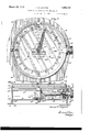
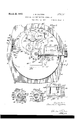
- FIG. 1 is a ace view of the dial and Fig. 2 is a sectional view with the casing, dial, deck plate andcompensator mechanism removed, and is substantially on line 2-2 ofFig.3.
- Fig. 3 is an axial sectional view through the han'd-stafl' and along the axis of the resettingmechanism, on line 3-3 of Fig. 2.
- Fig. 4 is an end view of the resetting mechanism, with the, hand knob eliminated for greater clearness.
- Fig. 5 is a section of the resetting mechanism, with other parts eliminated, substan tially on line 55 of Fig. 3.
- Fig. 6 is a sectional view through the hand staff and sleeves, taken on a diametral plane.
- V Fig. 7 is a detail section showing the reverse side of the deck plate.
- Fig. 8 is a plan view of mechanism as a unit.
- the compensating Fig. 9 is a sectional View of the compensating mechanism substantially on line 9-9 of Fig. 8.
- Fig. 10 is a sectional view showing the relationship of the hand stafi' knurled ring and its associated knurled disk on the resetting mechanism.
- Fig. 10a is a plan of the hand stafi knurled ring.
- Fig. 11 is a view of the reverse side of the base plate, to indicate the actuating lever for the shutter, the sealing means and the driver member.
- Fig. 12 is a fragmentary view showing the mode of assembly of the two parts of the guard band, on line 12-12 of Fig. 2.
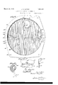
- Fig. 13 is a view on an enlarged scale of the compensating cam of the deck plate.
- Fig. 14 is a sectional view through the double clutch employed with the driver member, substantially on line 14-14 of Fig. 15.
- Fig. 15 is a section of the same clutch, on line 1515 of Fig. 14.
- Fig. 16 is a plan view of a modified compensator unit.
- Fig. 17 is a section through the sealing means, substantially on line 17-17 of Fig. 2.
- Fig. 18 is an end View of the driving washer.
- Fig. 19 is a side elevation of one guard band.
- Fig. 20 is a plan of the same band.
- Fig. 21 is another side elevation of a part of this same guard band, showing the lock with the other band.
- Fig. 22 is a plan of the other guard band with a fragment of the first band.
- Fig. 23 is a side elevation of this other band.
- Fig. 24 is a face View of a fragment of the dial with a modified form of resetting stop.
- Figs. 25 and 26 are sections on lines 2525 and 2626 of Fig. 24 respectively.
- the counting device has the base 10 having the cylindrical section 11 and the outwardly extending flange 12.
- the flange 12 is provided with the holes 13 to permit securing this base plate to a suitable support.
- the base plate portion 10 receives the elements of the transmitting train, the compensating mechanism, the counting mechanism. the dial and hand system, and the reset mechanism.
- a deck plate 14 is held in parallel spaced relationship to the base plate 10 by means of the three pillars 15 which have reduced ends to pass through apertures in the deck plate and the base plate: the ends of these pillars extending through the deck plate 14 are upset to form the rivet heads 15a, so that the pillars are held immovably with regard to the deck plate, whereby an unauthorized person is unable to separate the deck plate 14 from the rivets 15a.
- the pillars 15 extend through their respective apertures in the base plate 10 and are held by the nuts 15?) as shown in Fig. 12.
- the length of the reduced portion of the pillars which extend through the base plate 10 is such that when a single nut 15?) is locked in position as by a sealing wire 16 and the lead seal 16a, it is impossible to remove the other pillars from the base plate 10, and hence it is only possible to re move the deck plate by breaking the seal.
- the dial 17 (Fig. 1) is preferably white and has indicia, including the index marks 18 and the numerals 19 arranged in a circle on its face. supposed that the device is intended for the measurement of gallons, for which indicia have been provided, up to and including 20. It will be noted that the main indices for unit gallons have been sub-di vided into halves and quarters. Playing over this dial and cooperating with the indices is the pointer or hand 20 which is secured to a central shaft and actuated in the manner to be described hereinafter.
- the dial 17 is mounted above and rigidly connected to the deck plate 14 by means of the several screws 17a which pass through the spacer collars 17 b as shown in Fig. 3, whereby the dial, hand, deck plate, and base plate may be assembled and handled as a unit.
- the driver member 21 (Fig. 11) is provided with the upstanding lugs 21a which aiford a space therebetween for the reception of the driving element of a coaxial shaft: this shaft is driven in oscillation by the pump handle while the pump is being actuate so that the driving member 21 follows exactly all movements of the pump, no matter how small they may be.
- the driving member 21 also has a downwardly extending lug 21b which projects through the flanged cup 22 which has its flange brought into close contact with the cover plate 10 through which it projects.
- a packing ring 22a is provided to fit just within the downwardly extending flange of the cup 22 and around its edge so that it is brought into close and packing relationship with the base plate 10, to prevent the entry of dust and water around this edge.
- a similar cup 23 is provided on the other side of the base plate 10, which is perforated between these two cups by an aperature of substantial diameter.
- the clutch rings 24, 25 are located within the space formed by the cup 22, 23.
- a clutch core 26 of hardened steel is passed substantially axially through the aperture in the base plate 10 and conccntrically within the cups 22. 23.
- the clutch rings 24, 25 are located about the core 26 and are separated by a spacing ring 27.
- the clutch ring 25 is provided with three peripherally spaced notches 25a, each of which has its peripheral wall slightly divergent from the periphery of the core 26.
- a ball 28 and a coil spring It has in the present instance been 29 are located in each of these notches: these elements are of a diameter slightly less than the thickness of the material of the respective ring 25, so that no binding will occur.
- the ring 24, constructed exactly the same, has its balls and springs directed in the same direction.
- Each of these members is rovided with a notch 30 at its periphery. t will be understood that the members are identical in shape and design, and may be interchanged in assembly without loss of accuracy of function.
- the downwardlyextending lug 21b of the driving member 21 passes through an aperture in the cup 22 and is received in the notch 30 of the clutch ring 24, so thatthe clutch ring 24 is moved identically with the driving member 21, and hence with the pump.
- the second clutch ring 25 has a projecting lug 250: on the base plate 10 engaged in its respective notch 30, so that the clutch ring 25 is held against rotational movement about its own axis-
- This clutch ring therefore engages its respective balls 28 with the core 26 at-all times and serves as a retaining clutch or pawl to prevent any reverse rotation of the clutch core 26.
- the spacer 27 serves to prevent contact and blocking between the springs 29 and balls 28 of the respective rings 24, 25, so that the balls 28 and springs 29 are held within the respective notches of their respective rings by the cooperation of the spacing ring 27 and the inner walls of the cups 22, 23 respectively.
- the clutch core 26 is provided with a stub which extends thrpugh the cup 23 and receives a driving 131111011 31 on the other side thereof. Itv is preferred to extend the spindle 26a through a stra 32 and guide it therein.
- the strap 32 is fastened rigidly to the base plate 10 suitable screws, and serves to support and guide the shaft 26c as before mentioned. and likewise receives the spindle 33 form idler gear 34 which is in mesh with the pinion 81.
- a suitable gear ratio provides eleven teeth on the driving pinion 31 and thirty-two teeth on the idler 34.
- a further spindle 35 is fixedly mounted on the base plate 10 and extends upwardly therefrom to support the gear 36 of thirty-two teeth which is in mesh with the idler 34.
- the gear 36 is fixedly connected with a driving pinion 37 on its own spindle, of thirteen teeth.
- This driving pinion 37 in turn is in mesh with the driver plate gear 38 of the compensating device as shown in Fig. 1 and which, will be described more fully hereinafter: the driver plate gear 38 in the present instance is provided with sixty teeth.
- the compensating mechanism delivers its movement to a corrector plate pinion 39 which is likewise indicated in dotted lines in Fig. 2, and is provided with ten teeth.
- This pinion 39 is in mesh with anidler gear 40 of thirty-two teeth which is carried on a spindle 40a fixed in the base plate 10, and in turn is in mesh with the foot gear 41 of the hand-staff; which is provided with forty teeth.
- the foot ear 41 in turn is in driving relationship wit the first gear 42 of the counting train,'which in the present instance is provided with twenty teeth.
- This counting gear is mounted directly on a shaft 421 which is pivoted preferably in the plates 43 of the counting mechanism.
- the shaft 42a carries the dial 426 which has the successive indicia thereon which display through the respective openings 43a of the upper plate 43, so that the total number of gallons delivered may be read from the indications beneath the respective windows 4311. It will be understood that any appropriate type of transfer mechanism maybe employed to transmit a full rotation of the shaft 42a as a one-tenth rotation of the succeeding shaft,
- the counting mechanism is fastened by its plates 43 in some suitable manner to the base 10 so as to be held in fixed position thereon.
- the foot gear 41 is rigidly secured as by peening to a sleeve 44 which is journaled for loose rotation on the steel spindle 45 which has a spacer collar 46 and a threaded portion 4611 at its bottom for engagement in the base plate 10.
- a suitable nut 46d (Fig. 11) is employed to lock this spindle 45 in its position.
- a leather friction disk 47 is placed 20, which is held in such position by screws 50b passing through the screw holes 500.
- the lower portion of the hand sleeve 49 is formed internally for a close journal bearing about the sleeve 44, but for the greater part of its length is bored out internally to a greater diameter to receive the coil spring 51, which at its lower end reacts against the shoulder formed b this greater bore.
- a bushing 52 is inserte between the hand sleeve 49 and the inner sleeve 44 and substantially fills this space, while affording the hand sleeve 49 an upper bearing for its rotational movement with respect to the inner sleeve 44. It is preferred to internally chamfer the bushing 52 and to offset the upper end of the inner sleeve 44, whereby the sleeve 44 and the bushing 52 are held solidly together and form the upper reacting member for the coil spring 51, which thus is contained within an annular cavity formed by the integral hand sleeve 49 and the solidly connected inner sleeve 44 and its bushing 52.
- a knurled ring 53 having downwardly directed knurls is secured to the bottom of an outwardly extending shoulder of the head 50, and is held in such position and against rotation with respect to this head 50 by means of pins 53a.
- An annular stop bushing 54 is seated about the upper end of the steel spindle 45, and is locked thereto by a transverse pin 54a. which is passed through the pin slot 545 of the head 50, so that the head 50 may have a relative axial movement with respect to the spindle 45 and the sleeve 44.
- the reset mechanism for restoring the hand 20 from its actuated position to the zeroposition includes the knob 55 which projects to the exterior of the casing, and is mounted on a stub 56 which is in threaded relationship with the spindle 57 which in turn carries at its inner end the reset disk 58 (Fig. 10) which is knurled on its periphery and has a flattened portion 58a at the portion which is opposite the knurled ring 53 on the hand staff, so that this knurled ring, when the reset mechanism is in its inoperative position, is free of the knurled ring 53, and the latter is enabled to turn without any friction being placed upon it from the resetting mechanism.
- the spindle 57 is carried and guided in a sleeve 59 which is supported in a stirrup strap 60 which is fixedly bolted to the base plate 10 by screws 60a and it is preferred to provide the guide pins 605 in the base-plate to cooperate with apertures in the strap 60 to assure a perfect alinement of these parts.
- the end of the tube 59 adjacent the periphery of the base plate 10 is preferably offset into the chamfered hole in the upstanding outer end of the strap 60 so that the tube 59 and the strap 60 are held fixedly together.
- a clutch core 61 of hardened steel is provided with an outwardly extending stop flange 62 and an integral collar 63.
- This collar 63 is provided with a locking screw 63a and apertures for the transverse pins 635: it being understood that these pins pass throu h the apertures of the collar and into t e spindle 57, but are separated adjacent the axis of this spindle for the passage of the threaded portion 56 of the knurled head 55.
- a clutch ring 64 which is very similar to the clutch ring 25 above mentioned is located about the clutch core 61.
- a flattened portion 64b is provided on this clutch ring 64, which is provided internally with the tnree notches 64a, to receive the balls and springs 28, 29 as before.
- the notch 30 of this clutch ring 64 receives a stop or retaining member 65 which is riveted securely to the upstanding portion of the strap 60; whereby the clutch ring 64 is prevented from movement about its axis.
- TlllS pawl 70 is pivoted about the pin 66, and co operates at one position of rotatlon of the spindle 57 with a flattened portion 62a on the stop flange 62.
- An indicating polnter 55a is provided on the stub shaft of the knob 55. to indicate by sight or feeling the general position of the knob and its associated elements. 7
- the knob 55 When it is desired to reset the hand, the knob 55 is turned in a clockwise direction as viewed in Figs. 4 and 5, whereby the clutch core 61, spindle 57 and knurled disk 58 are turned clockwise, and the flattened portion 62a of the stop flange 62 forces the pawl 70 outward against the action of its spring 67, which is felt by the person attending the device as a considerable initial resistance to movement.
- the knurled disk 58 raises the hand staff system as indicated above, so that any frictional resistance from the foot gear 41 is eliminated.
- a continued rotation of the knob 55 produces a resetting of the hand 20 from any position in which it may be.
- the ratios of diameters of the engaging portion of the knurled disk 58 and of the knurled ring 53 shall be such that the hand 20 shall, for a complete revolution of the knob 55, be rotated beyond 360, whereby it is assured that the hand 20 will always be restored to the zero setting.
- a radial stop 71 is fixedly mounted on the face of the dial 17 and presents an upstanding edge to limit the movement of the hand, so that the latter may never go beyond the zero position during resetting.
- the compensating mechanism is constructed as follows: A driver plate and a corrector plate 81 are held fixedly in spaced relationship with regard to each other by spacer illars 82 and screws passing therethrough. ocated between these corrector plates are two corrector clutch rings 83 and 84, which are formed identically, except for size, to the rings 24, 25, 64, and need not be described in further detail. These rings 83, 84 have been made large in order to reduce the minimum registrable quantity. It has been found in practice that a .01 of an inch movement in the inner periphery of one of these compensator clutch rings is necessary to secure an easy operation of the clutch and an actuation of the corresponding amount throughout the mechanism, andthis represents a very minute percentage of a usual delivery.
- the driver plate gear 38 is secured to the driver plate 80 for movement therewith at all times.
- a clutch core 85 of hardened steel is mounted coaxially with the driver and corrector plates for movement with relation thereto, and extends through the two corrector clutch rings 83, 84 and comes approximately to the inner face of the driver plate.
- a spacing ring 86 is located between the two corrector clutch rings for the-purpose above indicated for the spacer ring 27.
- the corrector plate 81 is mounted on the upper face of the corrector plate 81. apivot 87 for the guide link 88. This guide link is connected by a pivot 89 to the adjustable or traveller nut 90 which is mounted on the adjuster screw 91.
- This adjuster screw 91 is freely rotatable in the corrector lever 92 which has upstanding ends to form journal bearings for the-screw 91.
- the screw 91 has a head 91a at its end adjacent the periphery of the corrector plate 81.
- the corrector plate 81 is provided with two slots 81a and 81?) through its face.
- the pivot pin 93 of the corrector lever 92 is fixedly mounted in the upper clutch ring 83, which likewise has the post 94 upstanding therefrom through the aperture 815, with a reduced stub at its upper end to receive the link 94a which is held thereon by a pin 946.
- a post 95 secured to the corrector plate 81 serves as a guide for the helical portion of a take-up spring 96, one arm of which engages in an aperture in the free end of the link 94a and the other end of which is secured beneath a reaction screw 97 which holds it fixedly to the corrector plate.
- a toggle break spring 98 may be connected by a post 980 on the corrector plate 81, and a screw 986 on the guide link 88 but this is not essential and is only employed in cases where the adjustment of the traveling nut 90 along the screw 91 may bring it to a position whereby, during the movement of the corrector lever 92, the centers of the pivots 93, 89 and 87 may extend in a straight line.
- a cam 100 On the lower side of the deck plate 14 is provided a cam 100 which is substantially of constant and equal rise.
- a post 101 extends downwardly from the deck plate through this cam and through a spacer 102, and passes through a post hole 101a through the cor rector. to the compensating mechanism.
- the axially directed end of the corrector lever 92 is provided with a cam dog 92a which rests against the periphery of the earn 100.
- the take-up spring 96 yields slightly, but at all times prevents any slackness or back-lash between the respective members: and at the moment that the cam dog 9% slips down the axial portion of the cam 100, the take-up spring 96 immediately snaps or erks the corrector clutch ring 83 back to its original position with respect to the corrector plate 81.
- the amount of the relative advance of the corrector clutch ring 83 with respect to the corrector plate 81 is uniform throughout a rotation of the cor rector plate 81, since the cam 100 is of constant and uniform rise. It will further be seen that the actual amount of this advance during a single revolution depends upon the ratio of the lever arms from the engaging point of the cam dog 92a to the effective center of the traveling nut 90, in proportion to the distance from the effective center of the traveling nut 90 to the pivot 93. It will be understood that the effective center of the traveling nut 90 depends upon the sizes and separations of the respective members, ineluding the traveling nut 90, the pivot 89,
- the lever ratio may be modified, and in particular that as the traveling nut 90 comes closer to the cam dog 92a, a greater and greater angular distance of movement is aforded to the corrector clutch ring 83, and that on the contrary, as the traveling nut 90 departs from the dog 92a, the relativemovement of the corrector clutch ring 83 becomes less and less until finally, when the effective center of movement of the traveling nut 90 is coincident with the axis 93, the corrector clutch ring 83 and the corrector plate 87 are rotated the same amount.
- the second clutch ring 84 is provided with its balls and springs directed in the same di rection as the corrector clutch ring 83, and is pinned to the driver plate so as to move therewith.
- the corrector clutch ring 84 with its own balls and springs lock with regard to the clutch core, and prevent any return movement thereof, thus maintaining the excess or advance movement of the clutch core with regard to the corrector and driver plates.
- a counter cam which comprises a lozenge-shaped plate 103 which is riveted fast to the deck plate 14, so that as the lever 92 is brought around in rotation about the axis of the post 101, its outward end is brought into engagement with the counter cam and caused to move downward until the dog 92a is again in engagement with the periphery of the cam 100.
- this plate 103 represents a portion of the outer track of a grooved cam whose inner track is the periphery of the cam 100: and that in particular the side 103aof the cam plate 103 is parallel to and causes a movement of the dog 92a along the radial line 1036 of the post 101. It will be understood that this plate 103 is provided as a matter of safeguard in case that the auxiliary spring 98 should fail to function. The plate 103 and spring 98 are in a. way alternative. devices, since the structure will operate with either one alone.
- the traveling nut 90, and the guide link 88 and other members is compensated by balancing the compensating mechanism about its axis by slipping the counterweight 104 around beneath its screw 105 when the latter is slightly loose. The counterweight is then tightened into position, and it is no longer possible to secure a fraudulent change of the mechanism by jarring.
- the clutch core 85 is provided with a tubular sleeve 850 which passes through the driver plate 80 and its driver plate gear 38 and, is provided with the pinion 39 which is fixed to this sleeve 85a in some suitable manner, as by peening.
- a casing is providedaround the whole. It is preferred to form the base plate 10 by stamping from sheet material such as steel, whereby to form the setting flange 12, the barrel flange 11 and the base plate proper 10.
- the casing 110 is likewise preferably formed of sheet material formation, into shape to have'a slight outward enlargement 111 atthe base adjacent the barrel flange 11, so that the cork packing ring 112 maybe cemented into position in this enlargement, so that when the easing 110 is seated upon the barrel flange 11, a dust and water-tight joint is formed.
- the casing 110 is provided with a protective rolled bead 113 which terminates with an inward flange 114 which serves as a seat for the glass pane 115.
- putty is placed in the bead 113 and the glass pane 115 is placed into position and forced home until the putty is extruded around the edges of the pane of glass, as shown, whereby a-resilient and tight seating is provided for the pane of glass, and all entry of dust and water into the casing at this point is prevented.
- the putty is then scraped away substantially flush with the glass pane 115, and a small felt ring 116 is placed in position at the periphery of the glass, and held in position by a split metal ring 117: this felt ring and the split ring being received within a shallow groove in the casing 110.
- the glass pane and easing constitute a further unit which is inherently water and dusttight, and is packed with regard to the base plate to form a water and dust-tight connection at this point.
- all holes in the base plate are filled by their respective pivot or screw posts, so that it is not possible for dust or water to enter the casing, and thus interfere with the operation of the counting and compensating mechanisms.
- the cap between the deck plate 14 and the cover plate 10 is closed by the two bands 120 and 121.
- the band 121 is provided with an eye 122 which receives the hook 123 on the band 120, so that these members are locked together against separation.
- the band 121 is further provided with a notch 121a for the reset shaft tube 59, and with a notch 121?) for the supporting strap for this reset mechanism.
- the guard band 121 is provided at one edge with an adjusting hole 125a and at its other edge with a lock lug 124.
- the other strap, 120 is provided at its other end with an adjusting hole 125?), and with a notch 124?) for the lock lug 124.
- An aperture 126 is provided in the base plate 10 and is in line with the threaded hole in the lock lug 124 when the guard bars 120, 121 are in position, as shown in Fig. 2; and a sealing screw 127 may be passed through the aperture of the base plate 10 and into the threaded hole of the lock lu 124, so that the two bands are held immova ly in position.
- the adjusting holes 125a, 1256 are alined; and furthermore a downwardly extending adjustment shield 129 is secured to the deck plate 14 and has itself an adjusting hole 1250, (Fig.
- cam 100 is so disposed with regard to the direction of its radial portion that when the cam dog 92a of the correcting lever 92 has just slipped down the radial face of this cam 100, the head 91a on the adjuster screw 91 is presented in alinement with the adjust-.
- a hole inthe casing for the purpose of ad- 0 justment is normally closed by the threaded plug 110a whose head fits a recess in the easmg 110.
- a further protection against the entry of dust and water into the casing is provided by the packing gland around the resetting shaft, which comprises a collar 130 which has the pins 131 assing through the side of the casing at a attened point of the latter, so
- an aperture 14011 is providedin the deck plate 14 above its outward surface with the same color as the body of the dial.
- This shutter is fixedly secured to shutter post 142 (Figs. 1, 2 and 7) which passes through apertures of the deck and base plates, and receives the collar 143 beneath the base plate.
- the collar 143 has an extending lever arm 144 which is movable between the stops 145 and 146. The owner of the station may at any time move the shutter lever 144 from the rear side of the device from the stop 145 to the position against stop Y 146, whereby the shutter 141 will be moved downward and out of closing relation to the aperture 1406, and the counting device may be easily read.
- the lever 144 After reading, the lever 144 is moved back to its position in contact with the stop 145, and the aperture 1406 is closed again. It is preferred to provide a rivet head 147 on the base plate, over which the lever 144 must move by its own resiliency, so that when the lever reaches its final position for the closed shutter, the resiliency of the lever will hold it in this position against vibratory displacement.
- the corrector plate 81 is provided as before, but the cam dog 150 is disposed to move radially in guides 151 on this corrector plate. 81.
- the thrust link 152 is pivoted to the cam dog 150 at its outer end and is connected to the pivot point 9311 on the corrector clutch ring 83. As the cam dog 150 s forced radially outward, a resultant thrust is given along the link, which results in a relative peripheral advance of the corrector clutch ring with regard to the corrector plate itself, with the results and for the purposes set forth above.
- the actuating handle shaft (not shown) in known manner causes the movement of the driver member 21 and through the double clutch a movement of the driving gear 31. This occurs in one direction of drive only, for example in a counter-clockwise direction in Fig. 2. On the contrary, when the handle shaft returns, it moves freely with the driver member 21 without an actuation of thedrive gear 31, as has already been described above.
- the ultimate movement of the clutch ring 83 is therefore that of the corrector plate 81 plus a small increment suflicient to correct for the irregularity or departure from standard, of the given pump. It may be remarked that in an actual device which has been constructed and. tested, the normal ratio of drive from the driving member to the compensator involved a movement of about 2.625 revolutions for one gallon as the theoretically exact angular distance of rotation for correct totalizing and in the device itself, the initial ratio was 2.685, or a loss of about 2% in the angular distance of rotation.
- the gear trains and individual gears are figured according to the direction of the movement for pumping and for registry of the pump handle which is to be totalized, and according to the ratio of movement of the pump handle with regard to the indicating hand and totalizer and involves changes of the gears 31, 36, 37, 38 and 39 for the change, for example, from registration of a gallon volume to the registration of a litre volume for a given indicating dial and counting mechanism.
- the axes of idler gears 34 and 40 may be located at other positions if necessary for the transmission of the movement, but without modification of their number of teeth: and that if it be desired to change the number of figures on the indicating dial, a suitable change maybe made in the ratios of the gears 41 and 42.
- the custodian therefore is unable to cheat the customer by fraudulently advancing the hand without delivery of gasoline, or by failing to otherwise until the mechanic hears the click resulting from the passage of the cam dog 92a from the maximum to the minimum diameter of the cam 100.
- the head 91a of the adjuster screw 91 is opposite the adjustment hole 1250 at the shield 129, and therefore in line for presentation of the screw driver into its slot.
- the mechanic then accomplishes the adjustment either by increase or decrease until the standard delivery is obtained with a standard indication on the indicating hand and the counting mechanism represented by the plates 43.
- the screw driver is then removed and the sealing screw 127 is screwed home and the sealing wire 16 and seal 16a are placed thereon: which operation may be accomplished by a state authority if such be required or available for calibrating of measurements.
- the plug 110a may now be replaced and screwed tight: and then the knob 55 with its stub shaft 56 may be threaded through the cork packing 132 and into the internally threaded spindle 57.
- Figs. 24, 25 and 26 The modified form of construction of this stop is shown in Figs. 24, 25 and 26 in which the stop 710 is secured to the dial 17 as before and extends toward the axis of movement of the hand 20, and has a cut-away portion as shown in Figs. 25 and 26 for the free passage of the hand at its lower plane of movement: and affords an extending'portion 71d to stop the hand positively during its return at the higher. plane,-as shown in dotted lines in Fig. 25.
- the under surface of the extension 71d is beveled so that no stoppage occurs even as the hand 20 is bent out of its true position: since if it is bent downward, a frictional contact with the dial 17 occurs which is immediately visible to the inspector: and if it be bent forwardly by a slight distance, the beveled surface is encountered and the hand is permitted to continue past the mark 20. It should be pointed out, however, that since the usual delivery is less than twenty gallons it is not customary for the hand to pass entirely around the scale.
- this compensating device and the counting mechanism and associated parts are to be mounted as a whole upon the body of a dispensing pump in any suitable manner, for example by means of screws or bolts passing through apertures 13 of the flange 12.
- gear train is used broadly to designate a transmitting means between the driver member and indicating or counting mechanism, into which the compensator may be inserted for correcting the ratios of rotative movement under the successive impulses from the driver member.
- the expression counting mechanism has been used broadly to designate either the totalizing mechanism or the hand for designating the quantity of the particular sale, since both are counting mechanisms and both are subjected to the corrective effect of the compensator.
- a counting mechanism a driver member, means to transmit the movement of said member to said mechanism, said means including a stationary cam, two relatively movable members, one of said members being driven from said driver member and the other being in driving relation to said counting mechanism, means on one of said relative movable members to cooperate with said cam to advance the other member in precession with'regard to itself, and means to sum up such movements of precession.
- a device of the character described including a counting mechanism fastened to said base plate and a driver member rotatable in said base plate and means to transmitmovement from said driver member to said mechanism, said transmitting means including an adjustable compensator to correct the movement of said mechanism with respect to the movement of said driver member, the combination of a guard having an opening therein to permit adjustment of said compensator, and a sealing device to secure said guard upon said base plate and about said compensator, said sealing device in one position serving to obstruct said opening.
- a driver' member and a gear train including a compensator to actuate said mechanism by movement derived from said driver member;
- said compensator comprising a corrector platedriven' from said driver member and a clutch core driving said counting mechanism, a correcting and a retaining clutch ring having ball clutch engagement with said clutch core, afixed cam, a corrector member on said corrector plate movable in rotation therewith and thereby actuated by said cam, means whereby said corrector member actuates said corrector ring'and therewith said clutch core at a difierential rate with respect to said corrector plate, and means to return said corrector clutch ring after having traversed said said driver member to move idly in the reverse direction whereby said mechanism will sum up the total movements in the said first direction;
- said train including two relative- 1y movable members, one of said members being driven from said driver member and the other'said member being in driving relation to said mechanism, and a take-up spring actmg relatively between said members whereby to absorb the
- a counting mechanism to transmit the movement in one direction of said driver member to said mechanism as a continual rotation thereof and to permit said driver member to move idly in the reverse direction whereby said mechanism will sum up the total movements in said first direction;
- said train including a compensator having two relatively movable rotatable members, a lever pivoted to one of said members and having a jointed connection to the other of said members, a fixed cam to cooperate with said lever to cause a relative movement of said rotatable members, and a screw on said lever to vary the position of said jointed connection to said lever.
- a counting mechanism to transmit the movement in one direction of sand. drivenmember to said mechanism as a continual rotation thereof and to permit said driver: member to move idly in thereverse direction whereby saidmechanism will sum up the total movements in said first direction;
- sard train including a compensator having eearav two relatively movable rotatable members, a lever pivoted to one of said-members and having a jointed connection to the other of said members, a fixed cam to cooperate with said lever to cause a relative movement 0 said rotatable members, and a spring tomaintain said lever in engagementwith said cam.
- a counting mechanism to transmit the movements in one direction of said driver member to said mechanismas a continual rotation thereof and to permit said driver member to, move idly in the reverse direction whereby saidmechanism will sum up the total movements in said first direction;
- said train including a compensator having two relatively movable rotatable members, a lever pivoted to one of said members and having a jointed connection to the other of said members, a fixed cam to cooperate with said lever to cause a relative movement of said rotatable members, and a spring to hold said rotatable members against such relative movement and thereby force said lever into engagement with said cam.
- a counting mechanism to transmit the movements in one direction of said driver member to said mechanism as a continual rotation'thereof and to permit said driver member to move idly in the reverse direction whereby said mechanism will sum up the total movements in said first direction;
- said train including a compensator having two relatively movable rotatable members, a lever pivoted to one of said members and having a jointed connection to the other of said members, a fixed cam to cooperate with said lever to cause a relative movement of said rotatable members, a spring to hold said rotatable members against such relative movement and thereby force said lever into engagement with said cam, and a second spring to prevent extension of said jointed connection beyond the lineof centers of said lever and connection.
- a counting mechanism to transmit the movements in one direction of said driver member to said mechanism as a continual rotation thereof and to permit said driver member to move idly in'the reverse d1rect1on whereby said mechamsm w1ll sum 'up the total movements in said first direction;
- said train including a compensator having two relatively movable rotatable members, alever pivoted to one of said members and having a jointed connection to the other of said members, a fixed cam to cooperate with said lever to cause a relative movement of said rotatable members, a spring to hold said rotatable members against such relative movement and thereby force said lever into engagement with said cam, a second spring to pr vent extension of said jointed connection beyond the line of centers of said lever and connection, and a second am to cooperate with said lever to force the same into engagement with said cam.
- a registering mechanism actuated from the pump mechanism, and transmitting means actuated by said driver member to operate said registering mechanism
- said transmitting means including a rotatable compensating element comprising two relatively movable portions and an unsymmetrically arranged connecting portion for establishing a driving relationship between said movable portions, and a counterweight on said element so that said element is balanced symmetrically about its axis of rotation so that fraudulent or accidental movements thereof cannot be produced by employment of inertia effects.
- the compensating mechanism includes means to cause said counting mechanism to be ad vanced in rotation an angular distance greater than the movement determined by said summing means and said connecting means.
- a counting mechanism a driver member
- a compensator comprising two relatively movable elements of which one is driven by said driver member, a lever having an adjustable arm ratio pivoted at one end to one of said elements and carried thereby and deriving at its other fulcra a relative rocking movement whereby to cause a relative movement of said elements, and means to connect said other element to the counting mechanism.
- a counting mechanism a driver member
- a compensator comprising two relatively movable elements of which one is driven by said driver member, a lever connected pivotally to each of said elements, fixed means to rock said lever during the movement of said first element and in propor tion thereto whereby to produce a differential movement of said other element, and means to onnect said other element to the counting mechanism.
- a counting mechanism an indicating mechanism, a driver member, means actuated by said driver to sum up the movements thereof in one direction, a permanently connected driving train to transmit such summation of the movements to the counting mechanism and including a rotatable compensating device moved always in the same direction of rotation to vary the ratio of transmission of said means by a regulatable fraction thereof, and means operated from said.
- compensating mechanism to drive said indicating mechanism and including a clutch element whereby the indicating mechanism may be disconnected from the permanently connected driving train whereby the indicating mechanism may be reset without disconnection of said counting mechanism.
- actuating means permanently connected to said driver member and driven continually in the same direction thereby and operatively connected to said indicating mechanism for driving the latter, said actuating means including a compensating mechanism continually rotating in the same direction for increasing the distance of movement of said indicating mechanism by a predetermined fraction of the distance of movement of said driver member, and means to disconnect said actuating means from said indicating mechanism whereby the latter may be returned to initial position while the actuating means remains connected to said driver member.
- a device of the character described the combination of a base plate and a deck plate held in spaced relation thereto, a guard band located between said plates and forming therewith an enclosed space for receiving an adjustable compensator, said guard band having an opening therethrough to permit adjustment of said compensator, and a blocking device passing through one of said plates to secure said guard in position and to obstruct said opening.
- a device of the character described the combination of a base plate and a deck plate held in spaced relation thereto, a guard band in two parts having interlocking means at the ends of each part, said bands being located between said plates and forming therewith an enclosed space for receiving an adjustable compensator, one of said bands having two transversely aligned notches at its free end and the other band having a transversely aligned lug and notch at its free end, said lug entering one of said notches on said first band when said other notches are aligned, whereby to provide an opening through which said compensator may be adjusted, and a blocking device passingthrough one of said plates and said lug whereby to secure said bands in position. said device also serving in one position to obstruct said other notches whereby to prevent access to said compensator therethrough.
- a counting mechanism a driver member, a compensating mechanism having a first rotatable member and a second rotatable member and a coupling means operated by the first member for advancing the second member at a diflr'erent rate of speed and including a device-for varying said rate of speed, means permanently connected to said driver member and driven continually in the same direction thereby and operatively connected to said first member for continually rotating the same in the same direction, means for preventing retrograde movement of said first member. and means for connecting said second member to the counting mechanism.
- a counting mechanism having a first and a second rotatable member and a coupling means operated by the first member for advancing the second member at a greater rate of speed and including a device for yarying said rate of speed, means for connectmg said driver member to said first member, means for preventing retrograde movement of said first member, and means for connecting said second member to said counting mechanism.
Description
March 1932- J. M. DAYTON 1,850,127
' COUNTING AND COMPENSATING MECHANISM Filed Feb 12, 1927 5 Sheets-5116GT. l
LL M Le zhmmza yfozv,
March 22, 1932. J. M. DAYTON COUNTING AND COMPENSATING MECHANISM 5 Sheecs-She 2 Filed Feb. 12.
March 22, 1932. DAYTON COUNTING AND COMPENSATING MECHANISM Filed Feb. 12, 1927 5 Sheets-Sheet 3 Mamh 22, 1932.
J. M. DAYTON 1,85%127 COUNTING AND COMPENSATING MECHANISM Filed Feb. 12, 1927 5 Sheets-Shear. 4
March 22, 1932. J. M. DAYTON COUNTING AND COMPENSATING MECHANISM Filed Feb. 12. 1927 5 Sheets-Sheet Patented Mar. 22, 1932 UNITED STATES JAMES M. DAYTON, 0F TORRINGTON, CONNECTICUT COUNTING AND COMPENSAT'ING MECHANISM Application filed February 12, 1927. Serial No. 167,799.
This invention relates to improvements in compensating devices which are applicable for the correcting of constantly recurring errors in transmitting systems.
It involves certain modifications and improvements in the compensator device disclosed by my Patent No. 1,571,577, granted on Feb. :2, 1926, and similarly to that device is more particularly intended for employment in the compensating of the movement of a dispensing pump piston as transmitted to and measured by a counting mechanism, asfor example in the counting of the total number of gallons dispensed by a gasoline filling station pump: it will, however, be understood that the invention is not limited to such employment, but is described hereinafter by way of example in connection with such a device, although it will find employment in many arts.
It is well known that reciprocating gasoline dispensing pumps employ cylinders and pistons made of drawn tubing, and in consequence of differences arising duringthe course of fabrication, such cylinders and their pistons are not all of the same diameter, whereby it becomes necessary to vary the efl'ective stroke of the piston in order to produce the dispensing of a normal or standard quantity, as for example, one gallon. Since it is desirable to measure the dispensing not only of the full or unit quantity of one gallon with such a pump, but also the most minute fraction thereof, it has been found as pointed out in my aforesaid patent, that it is necessary to employ some compensating or correcting device between the pump actuating device and the counting mechanism, whereby such diflerences may be compensated for, or corrected, and even the smallest fraction of a unit volume be totalized by the counting mechanism. If. for example, the owner of the pump should place it in charge of a custodian, it is desirable that the owner of the pump should have an accurate check upon the total number of gallons which have been dispensed therethrough, since this is a measure of the money which should be turned over bv the custodian to the owner. It is found e s sential that the custodian should not be able to defraud either the customer or the owner by, on the one hand, dispensin the liquid without causing an actuation 0 the counting mechanism: and on the other hand, by making claim to the customer for a. quantity of gasoline which has not been fully delivered to him. For such reasons, it is essential that the pump should at all times be positively connected to the counting mechanism, and that the compensator should be of a type which will respond to even the smallest movement of the pump handle.
For this purpose and according to the present invention, a positive train of gears is employed to connect the pump shaft through a driver member with the counting mecha nism: and a compensating device is included in this gear train to establish automatically, continuously and regularly the necessary correction for the variation of the particular pump cylinder from the normal or standard. To this end, the movements of the driver member in one direction are caused to be summed, while the movements of the driver member in the other direction are free and without effect upon the counting mechanism. In this way, the movement of the gear train is continuously in one direction, and no variation or error comes into existence by reason of back-lash in the gears, provided there either for constructional reasons of ease of movement or arising by reason of wear of the several parts. The compensating device included in this ear train comprises two members, one of w ich is driven positively from the driver member and the other of which is driven from the said first member of the compensator device, but with a constant excess or advance movement over the motion of the said first member arising by reason of its drive from said driver member. The compensating device is particularly characterized by reason of the fact that it moves continuously in rotation, and is therefore competent and required to establlsh such com pensation or correction throughout the 360 of its rotation, and thereafter to reset such compensation for a further 360", etc.
Further, in connectlon with this invention there is employed an indicating hand whereby the customer is enabled to observe the approximate quantity of gasoline which is delivered to hlm, and by reason of the employment of the compensating device, the indi cations of this hand are calibrated and com pensated so that .a correct indication is given by the indicating hand, asto calibration of the compensator, regardless of the diameter of the particular pump. Means are provided herein for resetting this hand to its initial or zero position, and these means are provided entirely independently ofthe' connec tion of the counting mechanism through its train to the driver member, so that if the indicating handbeeven in the processof return movement, when the pump is actuated, yet the totalizing counting mechanism will receive its due movement as a safeguard to the owner of the pump. It is further provided that during the normal movement of the hand in dispensing the liquid, its parts shall be free fromengagement with the resetting mechanism, whereby the effort necessary for the actuation of the counting and indicating systems is reduced to a minimum: and on the other hand, the resetting mechanism is so disposed that during the operation of resetting, the hand and its associated parts are removed from substantial frictional engagement with the counting mechanism and its driving system, whereby the creation of back lash or undesired movements in any member of this system, or a frictional contact with any member of this system for erroneous and wrongful operation, is rendered impossible.
In the present invention there is furthermore provided means for enclosing and guarding against water and dirt, the essential moving elements of the apparatus, so that they are protected from excessive wear and the errors arising therefrom. A sealing system is further provided whereby the adjustments of the compensating elements are made accessible only to a: properly authorized person, and it is possible, to determine at all times whether anyattempt has been made to modify the compensator. This sealmg is accomplished without preventingthe owner of the pump or his custodian from replacing a broken sight glass, for example, and
thereby a State authorlty responsible for tho accuracy of the pump need not recalibrate the pump in the event of such breakage.
A means is further provided whereby the owner of the pump may readily examine the totalizlng counting mechanism to determine the number of gallons which have been dispensed by the pump since his last inspection: and such inspection is facilitated by the provision of such counting mechanism imme-.,
diately beneath the face of the dial, which is customarily kept in a clear light for inspectlOl'l by the customer. At the same time, means are provided whereb this counting mechanism is hidden from view except upon casin g.
actuation of elements which are normally not accessible to an unauthorized person.
In the construction of this device, the moving elements are counterbalanced so that no undesired operation may be accomplished by jarring or hammering upon the casing. Further, the several elements are so far as possible, assembled as" units, so that rupon removing the various parts for repair and ins ection no len th and tedious process P, a g y of re-assemblage 1s necessary: and on the otherhand, invcase ofinjury to any of the parts, a full unit may be substituted fora damaged unit, *whereby'the particular pump may be placed in operation sooner than if it were necessary to return all parts for factory readjustment. I
The glass .of the casing is provided with a water and dirt tight seal which is resilient in its'nature and preserves its tightness for long eriods of time.
A urthe'r and particular advantage of the present device is the fact that the reset mechanism cannot be returned without completing a full stroke, so that it is impossible for the custodian of the pump to defraud acustomer by leaving the indicating hand at'a higher reading than the zero positionat the beginning of a delivery. 1
In the construction of the apparatus many further and advantageous improvements are introduced for the purpose of making the whole non-susc'eptibleto fraudulent operation, and assuring that the device shalloperate in the intended manner. a
I With these and other objects in view as'will appear in the course of the-following specification and claims, taken in conjunction with the accompanying drawings, there is shown in the latter one principal illustrative form,
of construction and appllcationof this invention to employment with a gasoline dispensing pump of any suitable type.
In these drawin s2 s a Figure 1 is a ace view of the dial and Fig. 2 is a sectional view with the casing, dial, deck plate andcompensator mechanism removed, and is substantially on line 2-2 ofFig.3.
Fig. 3 is an axial sectional view through the han'd-stafl' and along the axis of the resettingmechanism, on line 3-3 of Fig. 2.
Fig. 4 is an end view of the resetting mechanism, with the, hand knob eliminated for greater clearness.
Fig. 5 is a section of the resetting mechanism, with other parts eliminated, substan tially on line 55 of Fig. 3.
Fig. 6 is a sectional view through the hand staff and sleeves, taken on a diametral plane. V Fig. 7 is a detail section showing the reverse side of the deck plate.
Fig. 8 is a plan view of mechanism as a unit.
the compensating Fig. 9 is a sectional View of the compensating mechanism substantially on line 9-9 of Fig. 8.
Fig. 10 is a sectional view showing the relationship of the hand stafi' knurled ring and its associated knurled disk on the resetting mechanism.
Fig. 10a is a plan of the hand stafi knurled ring.
Fig. 11 is a view of the reverse side of the base plate, to indicate the actuating lever for the shutter, the sealing means and the driver member.
Fig. 12 is a fragmentary view showing the mode of assembly of the two parts of the guard band, on line 12-12 of Fig. 2.
Fig. 13 is a view on an enlarged scale of the compensating cam of the deck plate.
Fig. 14 is a sectional view through the double clutch employed with the driver member, substantially on line 14-14 of Fig. 15.
Fig. 15 is a section of the same clutch, on line 1515 of Fig. 14.
Fig. 16 is a plan view of a modified compensator unit. n
Fig. 17 is a section through the sealing means, substantially on line 17-17 of Fig. 2.
Fig. 18 is an end View of the driving washer.
Fig. 19 is a side elevation of one guard band.
Fig. 20 is a plan of the same band.
Fig. 21 is another side elevation of a part of this same guard band, showing the lock with the other band.
Fig. 22 is a plan of the other guard band with a fragment of the first band.
Fig. 23 is a side elevation of this other band.
Fig. 24 is a face View of a fragment of the dial with a modified form of resetting stop.
Figs. 25 and 26 are sections on lines 2525 and 2626 of Fig. 24 respectively.
In these drawings, the counting device has the base 10 having the cylindrical section 11 and the outwardly extending flange 12. The flange 12 is provided with the holes 13 to permit securing this base plate to a suitable support. The base plate portion 10 receives the elements of the transmitting train, the compensating mechanism, the counting mechanism. the dial and hand system, and the reset mechanism.
A deck plate 14 is held in parallel spaced relationship to the base plate 10 by means of the three pillars 15 which have reduced ends to pass through apertures in the deck plate and the base plate: the ends of these pillars extending through the deck plate 14 are upset to form the rivet heads 15a, so that the pillars are held immovably with regard to the deck plate, whereby an unauthorized person is unable to separate the deck plate 14 from the rivets 15a. At the other end the pillars 15 extend through their respective apertures in the base plate 10 and are held by the nuts 15?) as shown in Fig. 12. It will be understood that the length of the reduced portion of the pillars which extend through the base plate 10 is such that when a single nut 15?) is locked in position as by a sealing wire 16 and the lead seal 16a, it is impossible to remove the other pillars from the base plate 10, and hence it is only possible to re move the deck plate by breaking the seal.
The dial 17 (Fig. 1) is preferably white and has indicia, including the index marks 18 and the numerals 19 arranged in a circle on its face. supposed that the device is intended for the measurement of gallons, for which indicia have been provided, up to and including 20. It will be noted that the main indices for unit gallons have been sub-di vided into halves and quarters. Playing over this dial and cooperating with the indices is the pointer or hand 20 which is secured to a central shaft and actuated in the manner to be described hereinafter. The dial 17 is mounted above and rigidly connected to the deck plate 14 by means of the several screws 17a which pass through the spacer collars 17 b as shown in Fig. 3, whereby the dial, hand, deck plate, and base plate may be assembled and handled as a unit.
The driver member 21 (Fig. 11) is provided with the upstanding lugs 21a which aiford a space therebetween for the reception of the driving element of a coaxial shaft: this shaft is driven in oscillation by the pump handle while the pump is being actuate so that the driving member 21 follows exactly all movements of the pump, no matter how small they may be. The driving member 21 also has a downwardly extending lug 21b which projects through the flanged cup 22 which has its flange brought into close contact with the cover plate 10 through which it projects. A packing ring 22a is provided to fit just within the downwardly extending flange of the cup 22 and around its edge so that it is brought into close and packing relationship with the base plate 10, to prevent the entry of dust and water around this edge. A similar cup 23 is provided on the other side of the base plate 10, which is perforated between these two cups by an aperature of substantial diameter. The clutch rings 24, 25 are located within the space formed by the cup 22, 23. A clutch core 26 of hardened steel is passed substantially axially through the aperture in the base plate 10 and conccntrically within the cups 22. 23. The clutch rings 24, 25 are located about the core 26 and are separated by a spacing ring 27. As shown in Fig 15, the clutch ring 25 is provided with three peripherally spaced notches 25a, each of which has its peripheral wall slightly divergent from the periphery of the core 26. A ball 28 and a coil spring It has in the present instance been 29 are located in each of these notches: these elements are of a diameter slightly less than the thickness of the material of the respective ring 25, so that no binding will occur. The ring 24, constructed exactly the same, has its balls and springs directed in the same direction. Each of these members is rovided with a notch 30 at its periphery. t will be understood that the members are identical in shape and design, and may be interchanged in assembly without loss of accuracy of function.
The downwardlyextending lug 21b of the driving member 21 passes through an aperture in the cup 22 and is received in the notch 30 of the clutch ring 24, so thatthe clutch ring 24 is moved identically with the driving member 21, and hence with the pump.' As
this clutch plate 24'moves in one direction,
its balls 28 engage the clutch core 26 and ad- Vance it at the same rate and in the same proportion. As soon as the direction of movement of the driving member 21 reverses, the clutch ring 24 likewise reverses in direction of movement, but now its balls 28 disengage the clutch core 26, so that the ring 24 turns substantially free from the clutch core 26, and the latter remains in its actuated position.
The second clutch ring 25 has a projecting lug 250: on the base plate 10 engaged in its respective notch 30, so that the clutch ring 25 is held against rotational movement about its own axis- This clutch ring therefore engages its respective balls 28 with the core 26 at-all times and serves as a retaining clutch or pawl to prevent any reverse rotation of the clutch core 26. The spacer 27 serves to prevent contact and blocking between the springs 29 and balls 28 of the respective rings 24, 25, so that the balls 28 and springs 29 are held within the respective notches of their respective rings by the cooperation of the spacing ring 27 and the inner walls of the cups 22, 23 respectively. The clutch core 26 is provided with a stub which extends thrpugh the cup 23 and receives a driving 131111011 31 on the other side thereof. Itv is preferred to extend the spindle 26a through a stra 32 and guide it therein. This type of dou le ball clutchis further described and claimed, and its advantages set forth in my cooending application Serial No. 196,320, filed June 3, 1927, and no claim to its specific assembly or arrangement is made in the pres. ent application.
The strap 32 is fastened rigidly to the base plate 10 suitable screws, and serves to support and guide the shaft 26c as before mentioned. and likewise receives the spindle 33 form idler gear 34 which is in mesh with the pinion 81. In a particular instance, where the meter is annoy d for measuring gallons, 1t has been f dund that a suitable gear ratio provides eleven teeth on the driving pinion 31 and thirty-two teeth on the idler 34. A further spindle 35 is fixedly mounted on the base plate 10 and extends upwardly therefrom to support the gear 36 of thirty-two teeth which is in mesh with the idler 34. The gear 36 is fixedly connected with a driving pinion 37 on its own spindle, of thirteen teeth. This driving pinion 37 in turn is in mesh with the driver plate gear 38 of the compensating device as shown in Fig. 1 and which, will be described more fully hereinafter: the driver plate gear 38 in the present instance is provided with sixty teeth. The compensating mechanism delivers its movement to a corrector plate pinion 39 which is likewise indicated in dotted lines in Fig. 2, and is provided with ten teeth. This pinion 39 is in mesh with anidler gear 40 of thirty-two teeth which is carried on a spindle 40a fixed in the base plate 10, and in turn is in mesh with the foot gear 41 of the hand-staff; which is provided with forty teeth. The foot ear 41 in turn is in driving relationship wit the first gear 42 of the counting train,'which in the present instance is provided with twenty teeth. This counting gear is mounted directly on a shaft 421 which is pivoted preferably in the plates 43 of the counting mechanism. The shaft 42a carries the dial 426 which has the successive indicia thereon which display through the respective openings 43a of the upper plate 43, so that the total number of gallons delivered may be read from the indications beneath the respective windows 4311. It will be understood that any appropriate type of transfer mechanism maybe employed to transmit a full rotation of the shaft 42a as a one-tenth rotation of the succeeding shaft,
etc., whereby the counting mechanism is actuated. Such devices are very old and well known in the art, and the specific assembly forms no portion of this invention, and need not be more fully described herein. The counting mechanism is fastened by its plates 43 in some suitable manner to the base 10 so as to be held in fixed position thereon.
The foot gear 41 is rigidly secured as by peening to a sleeve 44 which is journaled for loose rotation on the steel spindle 45 which has a spacer collar 46 and a threaded portion 4611 at its bottom for engagement in the base plate 10. A suitable nut 46d (Fig. 11) is employed to lock this spindle 45 in its position. A leather friction disk 47 is placed 20, which is held in such position by screws 50b passing through the screw holes 500. The lower portion of the hand sleeve 49 is formed internally for a close journal bearing about the sleeve 44, but for the greater part of its length is bored out internally to a greater diameter to receive the coil spring 51, which at its lower end reacts against the shoulder formed b this greater bore. A bushing 52 is inserte between the hand sleeve 49 and the inner sleeve 44 and substantially fills this space, while affording the hand sleeve 49 an upper bearing for its rotational movement with respect to the inner sleeve 44. It is preferred to internally chamfer the bushing 52 and to offset the upper end of the inner sleeve 44, whereby the sleeve 44 and the bushing 52 are held solidly together and form the upper reacting member for the coil spring 51, which thus is contained within an annular cavity formed by the integral hand sleeve 49 and the solidly connected inner sleeve 44 and its bushing 52. A knurled ring 53 having downwardly directed knurls is secured to the bottom of an outwardly extending shoulder of the head 50, and is held in such position and against rotation with respect to this head 50 by means of pins 53a. An annular stop bushing 54 is seated about the upper end of the steel spindle 45, and is locked thereto by a transverse pin 54a. which is passed through the pin slot 545 of the head 50, so that the head 50 may have a relative axial movement with respect to the spindle 45 and the sleeve 44. It will thus be seen that the foot gear, friction leather disk, the two sleeves, and the upper bushing 52, and the, knurled ring 53 are assembled as a unit, and under normal conditions rest by their own weight upon the collar 46 of the spindle 45, so that no strain is placed upon this spindle, and even the driving strain of the meshing gears occurs very close to the base plate 10, and therefore has but very slight tendency to distort or move the spindle 45. Since the spring 51 reacts between the fixed sleeve 52 against the friction plate 48 and disk 47, and tothe foot gear 41 which in turn is rigidly secured in fixed relationship to the sleeve 52, it is apparent that no strain exists from this unit upon the stop bushing 54, and the spindle is not under any strain, and imposes no undue friction upon the driving train while counting and indicating is occurring. A flat spring 41a exerts a constant drag on the gears and prevents the development of back lash by-hammering the device.
The reset mechanism for restoring the hand 20 from its actuated position to the zeroposition includes the knob 55 which projects to the exterior of the casing, and is mounted on a stub 56 which is in threaded relationship with the spindle 57 which in turn carries at its inner end the reset disk 58 (Fig. 10) which is knurled on its periphery and has a flattened portion 58a at the portion which is opposite the knurled ring 53 on the hand staff, so that this knurled ring, when the reset mechanism is in its inoperative position, is free of the knurled ring 53, and the latter is enabled to turn without any friction being placed upon it from the resetting mechanism. As soon as the knurled disk 58 is rotated by means of the knob 55 and the shaft 57, the flattened portion is removed from opposite the knurled ring 53, and the circular portion of the disk 58 is brought into engagement with the ring 53, whereby the latter is forced upwardly, and in turn raises the hand sleeve 49 against the action of the coil spring 51, and thereby disengages the friction plate 48 from the leather 47, so that very little or no frictional resistance is offered by the foot gear 41 to the free movement of the hand sleeve 49. As the friction plate 48 is raised away from the foot gear 41, the upper end of the sleeve 44 and its bushing 52 are brought into contact with the stop bushing 54 on the spindle 45, whereby a slight friction is provided, and at the same time the parts are prevented from separating. After the knurled disk 58 has completed a full revolution, the flattened portion 58a again comes opposite the knurled ring 53, and the latter is lowered so that the friction plate 48 is again brought into contact with the disk 47 and thus with the foot gear 41, for frictional driving as before: and likewise the knurled ring 53 is finally left free of the knurled disk 58, so that again no frictional relationship exists between the two.
The spindle 57 is carried and guided in a sleeve 59 which is supported in a stirrup strap 60 which is fixedly bolted to the base plate 10 by screws 60a and it is preferred to provide the guide pins 605 in the base-plate to cooperate with apertures in the strap 60 to assure a perfect alinement of these parts. The end of the tube 59 adjacent the periphery of the base plate 10 is preferably offset into the chamfered hole in the upstanding outer end of the strap 60 so that the tube 59 and the strap 60 are held fixedly together.
A clutch core 61 of hardened steel is provided with an outwardly extending stop flange 62 and an integral collar 63. This collar 63 is provided with a locking screw 63a and apertures for the transverse pins 635: it being understood that these pins pass throu h the apertures of the collar and into t e spindle 57, but are separated adjacent the axis of this spindle for the passage of the threaded portion 56 of the knurled head 55. A clutch ring 64 which is very similar to the clutch ring 25 above mentioned is located about the clutch core 61. For convenience in assembly and to afford proper clearance of parts, a flattened portion 64b is provided on this clutch ring 64, which is provided internally with the tnree notches 64a, to receive the balls and springs 28, 29 as before. The notch 30 of this clutch ring 64 receives a stop or retaining member 65 which is riveted securely to the upstanding portion of the strap 60; whereby the clutch ring 64 is prevented from movement about its axis. It is preferred to form one of the rivets66 for the pad 65 as a guide pin for the helical coil of a spring 67 which engages one end in an aperture of a pin 68 secured in the upstanding part ofthe strap 60, and presents its other end against a stop pin 69 located on a stop pawl 7 O. TlllS pawl 70 is pivoted about the pin 66, and co operates at one position of rotatlon of the spindle 57 with a flattened portion 62a on the stop flange 62. An indicating polnter 55a is provided on the stub shaft of the knob 55. to indicate by sight or feeling the general position of the knob and its associated elements. 7
When it is desired to reset the hand, the knob 55 is turned in a clockwise direction as viewed in Figs. 4 and 5, whereby the clutch core 61, spindle 57 and knurled disk 58 are turned clockwise, and the flattened portion 62a of the stop flange 62 forces the pawl 70 outward against the action of its spring 67, which is felt by the person attending the device as a considerable initial resistance to movement. The knurled disk 58 raises the hand staff system as indicated above, so that any frictional resistance from the foot gear 41 is eliminated. A continued rotation of the knob 55 produces a resetting of the hand 20 from any position in which it may be. It is preferred that the ratios of diameters of the engaging portion of the knurled disk 58 and of the knurled ring 53 shall be such that the hand 20 shall, for a complete revolution of the knob 55, be rotated beyond 360, whereby it is assured that the hand 20 will always be restored to the zero setting. A radial stop 71 is fixedly mounted on the face of the dial 17 and presents an upstanding edge to limit the movement of the hand, so that the latter may never go beyond the zero position during resetting. When the hand has regained its zero position, the knurled ring 53 is held against movement, and thereafter the knurled disk 58 turns beneath it, successively raising the ring 53 somewhat higher as the teeth pass each other, but at all times maintaining the friction plate 48 away from the foot gear 41 until the flattened portion 58a comes opposite the knurled ring 53 as above described.
The compensating mechanism is constructed as follows: A driver plate and a corrector plate 81 are held fixedly in spaced relationship with regard to each other by spacer illars 82 and screws passing therethrough. ocated between these corrector plates are two corrector clutch rings 83 and 84, which are formed identically, except for size, to the rings 24, 25, 64, and need not be described in further detail. These rings 83, 84 have been made large in order to reduce the minimum registrable quantity. It has been found in practice that a .01 of an inch movement in the inner periphery of one of these compensator clutch rings is necessary to secure an easy operation of the clutch and an actuation of the corresponding amount throughout the mechanism, andthis represents a very minute percentage of a usual delivery. 'The driver plate gear 38 is secured to the driver plate 80 for movement therewith at all times. A clutch core 85 of hardened steel is mounted coaxially with the driver and corrector plates for movement with relation thereto, and extends through the two corrector clutch rings 83, 84 and comes approximately to the inner face of the driver plate. A spacing ring 86 is located between the two corrector clutch rings for the-purpose above indicated for the spacer ring 27.
Mounted on the upper face of the corrector plate 81 is apivot 87 for the guide link 88. This guide link is connected by a pivot 89 to the adjustable or traveller nut 90 which is mounted on the adjuster screw 91. This adjuster screw 91 is freely rotatable in the corrector lever 92 which has upstanding ends to form journal bearings for the-screw 91. The screw 91 has a head 91a at its end adjacent the periphery of the corrector plate 81. The corrector plate 81 is provided with two slots 81a and 81?) through its face. The pivot pin 93 of the corrector lever 92 is fixedly mounted in the upper clutch ring 83, which likewise has the post 94 upstanding therefrom through the aperture 815, with a reduced stub at its upper end to receive the link 94a which is held thereon by a pin 946. A post 95 secured to the corrector plate 81 serves as a guide for the helical portion of a take-up spring 96, one arm of which engages in an aperture in the free end of the link 94a and the other end of which is secured beneath a reaction screw 97 which holds it fixedly to the corrector plate. This take-up spring tends at all times to pull the clutch ring 83 counterclockwise with regard to the corrector plate 81, and thus imposes a constant take-up upon the entire system, and prevents any back-lash occurring at the beginning or ending of the registering movements. A toggle break spring 98 may be connected by a post 980 on the corrector plate 81, and a screw 986 on the guide link 88 but this is not essential and is only employed in cases where the adjustment of the traveling nut 90 along the screw 91 may bring it to a position whereby, during the movement of the corrector lever 92, the centers of the pivots 93, 89 and 87 may extend in a straight line.
On the lower side of the deck plate 14 is provided a cam 100 which is substantially of constant and equal rise. A post 101 extends downwardly from the deck plate through this cam and through a spacer 102, and passes through a post hole 101a through the cor rector. to the compensating mechanism. The axially directed end of the corrector lever 92 is provided with a cam dog 92a which rests against the periphery of the earn 100. It will be understood that as the corrector plate 81 is rotated about the axis of the post 101, the cam dog is forced outwardly by this cam 100, whereby the corrector lever 92 is caused to rock about pivots 89 and 87 in a compound motion, and its own pivot center 93 and the corrector clutch ring 83 is caused to move slightly clockwise in the position of Fig. 8. The cam 100 has been shown in dotted lines in this figure, and it is seen that this clockwise excess rotation of the corrector clutch ring 83 is accomplished during a clockwise rotation of the corrector plate 81 itself. During this movement, the take-up spring 96 yields slightly, but at all times prevents any slackness or back-lash between the respective members: and at the moment that the cam dog 9% slips down the axial portion of the cam 100, the take-up spring 96 immediately snaps or erks the corrector clutch ring 83 back to its original position with respect to the corrector plate 81.
It will be understood that during the relative clockwise advance of the corrector clutch ring 83 with regard to the corrector plate 81, the clutch ring with its balls and springs is tightly engaging the clutch core and rotat ing the same. Since this clutch core is engaged by the corrector clutch ring 83, it 18 caused to rotate for a slightly greater angular distance than the actual distance covered by the corrector plate 81 and its coupled driver plate 80 under actuation from the pump handle. The moment, however, that the cam dog slips down the radial face of the cam 100, the corrector clutch ring 83 loses its engagement with the clutch core, by reason of its reversal of movement and the disengagement of the balls and springs, and the corrector clutch ring 83 slips back, as noted, without effective operation of any kind, and under the impulse of the take-up spring 96.
It will be seen that the amount of the relative advance of the corrector clutch ring 83 with respect to the corrector plate 81 is uniform throughout a rotation of the cor rector plate 81, since the cam 100 is of constant and uniform rise. It will further be seen that the actual amount of this advance during a single revolution depends upon the ratio of the lever arms from the engaging point of the cam dog 92a to the effective center of the traveling nut 90, in proportion to the distance from the effective center of the traveling nut 90 to the pivot 93. It will be understood that the effective center of the traveling nut 90 depends upon the sizes and separations of the respective members, ineluding the traveling nut 90, the pivot 89,
the guide link 88 and the pivot 87. Since the sizes of these members are fixed in the original construction, it is ap arent that by a variation of the position of the traveling nut 90 along the threaded spindle or screw 91, the lever ratio may be modified, and in particular that as the traveling nut 90 comes closer to the cam dog 92a, a greater and greater angular distance of movement is aforded to the corrector clutch ring 83, and that on the contrary, as the traveling nut 90 departs from the dog 92a, the relativemovement of the corrector clutch ring 83 becomes less and less until finally, when the effective center of movement of the traveling nut 90 is coincident with the axis 93, the corrector clutch ring 83 and the corrector plate 87 are rotated the same amount.
The second clutch ring 84: is provided with its balls and springs directed in the same di rection as the corrector clutch ring 83, and is pinned to the driver plate so as to move therewith. During the quick return movement of the corrector clutch ring 83, when the clutch core is disengaged therefrom, the corrector clutch ring 84: with its own balls and springs lock with regard to the clutch core, and prevent any return movement thereof, thus maintaining the excess or advance movement of the clutch core with regard to the corrector and driver plates.
In order to assist the movement of the cam dog 92a in case that the take-up spring 96 does not snap the dog 92a along the axial portion of the cam, a counter cam is provided which comprises a lozenge-shaped plate 103 which is riveted fast to the deck plate 14, so that as the lever 92 is brought around in rotation about the axis of the post 101, its outward end is brought into engagement with the counter cam and caused to move downward until the dog 92a is again in engagement with the periphery of the cam 100. It may be stated that this plate 103 represents a portion of the outer track of a grooved cam whose inner track is the periphery of the cam 100: and that in particular the side 103aof the cam plate 103 is parallel to and causes a movement of the dog 92a along the radial line 1036 of the post 101. It will be understood that this plate 103 is provided as a matter of safeguard in case that the auxiliary spring 98 should fail to function. The plate 103 and spring 98 are in a. way alternative. devices, since the structure will operate with either one alone. It has been found that since a greater time is taken for the plate 103 to return the dog 92a to its contact with the periphery of the cam when the plates 80 and 81 have passed around a complete revolution of the radial portion of the cam and encountered, than is required by the spring 98 and the take-up spring 96 to snap the members back into position, a slight error comes into the correction by-reason of the angular dis- 104 which is fastened by a screw 105 disposed eccentrically in its mass to the corrector plate 81. The unbalanced mass of the corrector mechanism including the corrector lever 92,
the traveling nut 90, and the guide link 88 and other members, is compensated by balancing the compensating mechanism about its axis by slipping the counterweight 104 around beneath its screw 105 when the latter is slightly loose. The counterweight is then tightened into position, and it is no longer possible to secure a fraudulent change of the mechanism by jarring.
The clutch core 85 is provided with a tubular sleeve 850 which passes through the driver plate 80 and its driver plate gear 38 and, is provided with the pinion 39 which is fixed to this sleeve 85a in some suitable manner, as by peening. Y
It will be seen that the driver and corrector plates and the mechanism attached thereto are-held fixedly together, so that all theseelements may be inserted and removed as a unit, which is generally indicated in Fig.
2 of the drawings by the dotted lines representing the peripheries of the corrector plate 81, the gear 38, and the pinion 39.
In order to enclose and contain these pieces of mechanism, a casing is providedaround the whole. It is preferred to form the base plate 10 by stamping from sheet material such as steel, whereby to form the setting flange 12, the barrel flange 11 and the base plate proper 10. The casing 110 is likewise preferably formed of sheet material formation, into shape to have'a slight outward enlargement 111 atthe base adjacent the barrel flange 11, so that the cork packing ring 112 maybe cemented into position in this enlargement, so that when the easing 110 is seated upon the barrel flange 11, a dust and water-tight joint is formed. At the other end the casing 110 is provided with a protective rolled bead 113 which terminates with an inward flange 114 which serves as a seat for the glass pane 115. In assembling the device, putty is placed in the bead 113 and the glass pane 115 is placed into position and forced home until the putty is extruded around the edges of the pane of glass, as shown, whereby a-resilient and tight seating is provided for the pane of glass, and all entry of dust and water into the casing at this point is prevented. The putty is then scraped away substantially flush with the glass pane 115, and a small felt ring 116 is placed in position at the periphery of the glass, and held in position by a split metal ring 117: this felt ring and the split ring being received within a shallow groove in the casing 110. It will thus be seen that the glass pane and easing constitute a further unit which is inherently water and dusttight, and is packed with regard to the base plate to form a water and dust-tight connection at this point. Likewise, all holes in the base plate are filled by their respective pivot or screw posts, so that it is not possible for dust or water to enter the casing, and thus interfere with the operation of the counting and compensating mechanisms.
It has already been shown and described how the deck plate 14 and the base plate 10 are held against separation without breakage of a sealing device 16, 17. In order further to protect the mechanism from raudulent readjustment, the cap between the deck plate 14 and the cover plate 10 is closed by the two bands 120 and 121. The band 121 is provided with an eye 122 which receives the hook 123 on the band 120, so that these members are locked together against separation. The band 121 is further provided with a notch 121a for the reset shaft tube 59, and with a notch 121?) for the supporting strap for this reset mechanism. At its other end the guard band 121 is provided at one edge with an adjusting hole 125a and at its other edge with a lock lug 124. The other strap, 120, is provided at its other end with an adjusting hole 125?), and with a notch 124?) for the lock lug 124. An aperture 126 is provided in the base plate 10 and is in line with the threaded hole in the lock lug 124 when the guard bars 120, 121 are in position, as shown in Fig. 2; and a sealing screw 127 may be passed through the aperture of the base plate 10 and into the threaded hole of the lock lu 124, so that the two bands are held immova ly in position. sition, the adjusting holes 125a, 1256 are alined; and furthermore a downwardly extending adjustment shield 129 is secured to the deck plate 14 and has itself an adjusting hole 1250, (Fig. 2) which is in alinement with the adjusting holes 125a and 1256 under the conditions specified. Further, the cam 100 is so disposed with regard to the direction of its radial portion that when the cam dog 92a of the correcting lever 92 has just slipped down the radial face of this cam 100, the head 91a on the adjuster screw 91 is presented in alinement with the adjust-.
' It will be noted in Fig. 11 that the sealing wire 16 passes through the head of the sealing screw 127, as well as over the nut 156 and through the pillar 15: whereby a positive assurance is afforded against unauthorized modification of the compensating system.
I A hole inthe casing for the purpose of ad- 0 justment is normally closed by the threaded plug 110a whose head fits a recess in the easmg 110.
A further protection against the entry of dust and water into the casing is provided by the packing gland around the resetting shaft, which comprises a collar 130 which has the pins 131 assing through the side of the casing at a attened point of the latter, so
that there is a firm contact between the collar 130 and the side of the casing. These pins pass throu h apertures in the casing which are larger t an themselves, and have enlarged heads on the inside of the casing whereby the collar 130 is self-alining with respect to the resetting s indle. A. cork packing disk 132 is engaged tween the collar 130 and the side of the casing, and is held in packed relationship with the spindle. It is likewise preferred to form a water groove 133 on the stub spindle of the knob 55, to lead the rain water vertically downward.
In order to make the indications of the counting mechanism within the'plates 43 visi ble through theface of the dial, an aperture 14011 is providedin the deck plate 14 above its outward surface with the same color as the body of the dial. This shutter is fixedly secured to shutter post 142 (Figs. 1, 2 and 7) which passes through apertures of the deck and base plates, and receives the collar 143 beneath the base plate. The collar 143 has an extending lever arm 144 which is movable between the stops 145 and 146. The owner of the station may at any time move the shutter lever 144 from the rear side of the device from the stop 145 to the position against stop Y 146, whereby the shutter 141 will be moved downward and out of closing relation to the aperture 1406, and the counting device may be easily read. After reading, the lever 144 is moved back to its position in contact with the stop 145, and the aperture 1406 is closed again. It is preferred to provide a rivet head 147 on the base plate, over which the lever 144 must move by its own resiliency, so that when the lever reaches its final position for the closed shutter, the resiliency of the lever will hold it in this position against vibratory displacement.
In the modified form of the compensating system shown in Fig. 16, the corrector plate 81 is provided as before, but the cam dog 150 is disposed to move radially in guides 151 on this corrector plate. 81. The thrust link 152 is pivoted to the cam dog 150 at its outer end and is connected to the pivot point 9311 on the corrector clutch ring 83. As the cam dog 150 s forced radially outward, a resultant thrust is given along the link, which results in a relative peripheral advance of the corrector clutch ring with regard to the corrector plate itself, with the results and for the purposes set forth above.
The method of operation of this device is as follows: a
When the pump is actuated, the actuating handle shaft (not shown) in known manner causes the movement of the driver member 21 and through the double clutch a movement of the driving gear 31. This occurs in one direction of drive only, for example in a counter-clockwise direction in Fig. 2. On the contrary, when the handle shaft returns, it moves freely with the driver member 21 without an actuation of thedrive gear 31, as has already been described above.
As a result of this operation of the driving gear 31, the movement is successively transmitted to the idler gear 34 and gear 36 and thence with a reduction of movement to the pinion 37 and thence to the driver plate gear 38. This driver plate gear 38, being positively connected to the driver and corrector plates 80, 81, causes these plates to move in rotation in a clockwise direction, and by an angular amount which is in exact proportion to the movement of the pump handle, and as indicated above, it has been found in practice that any movement of the pump handle which will produce even as little as a .01 of an inch movement in the periphery of the clutch core 85, will be transmitted through the train. It will be noted that the gears of the tram move always in the same direction, and that by the provision of the retaining clutch 25 with its associated member, there is no slack or back-lash in this gear train, so that even the most minute movement is summed up.
As the corrector plate 81 rotates about the clockwise in the position of Fig. 8, this dog 92a is forced successively and uniformly outward by'the cam 100. As the lever 92 rocks, it turns about a virtual axis which is determined by the prevailing position of the traveling nut 90, as guided by the link 88 with regard to the pivot 87.- This produces a relative advance movement of the pivot 93 on the lever 92 with regard to the corrector plate 81, and since the pivot 93 passes through the aperture 81a, and is solidly fixed to the clutch ring 83, this clutch ring 1s caused to make a slight movement of precession with regard to the corrector plate 81, and against the action of the take-up spring 96. Since this movement may be calibrated or regulated by the position of the traveling nut 90 upon the adjuster screw 91, the ultimate movement of the clutch ring 83 is therefore that of the corrector plate 81 plus a small increment suflicient to correct for the irregularity or departure from standard, of the given pump. It may be remarked that in an actual device which has been constructed and. tested, the normal ratio of drive from the driving member to the compensator involved a movement of about 2.625 revolutions for one gallon as the theoretically exact angular distance of rotation for correct totalizing and in the device itself, the initial ratio was 2.685, or a loss of about 2% in the angular distance of rotation. This is compensated for or corrected by giving the clutch ring 83 a corresponding excess or advance movement with regard to the corrector late 81 corresponding to this 2% loss. In the actual device, this placed the traveling nut 90 about midway of the adjuster screw 91, whereby it was possible with this single device to correct for pumps which were as much as 2% above or below the standard or normal. Inasmuch as the usual departure seldom exceeds 1% over or under the standard size, it is apparent that a full range of correction is afforded, and by a suitable low pitch of the adjuster screw 91, this compensation may be made as accurate as required.
It is further apparent that in construction for the particular operation, the gear trains and individual gears are figured according to the direction of the movement for pumping and for registry of the pump handle which is to be totalized, and according to the ratio of movement of the pump handle with regard to the indicating hand and totalizer and involves changes of the gears 31, 36, 37, 38 and 39 for the change, for example, from registration of a gallon volume to the registration of a litre volume for a given indicating dial and counting mechanism. It will be understood that the axes of idler gears 34 and 40 may be located at other positions if necessary for the transmission of the movement, but without modification of their number of teeth: and that if it be desired to change the number of figures on the indicating dial, a suitable change maybe made in the ratios of the gears 41 and 42.
Returning to the action of the compensator, as soon as the cam dog 92a has reached the outermost point of the cam 100, the clutch ring 83 has been advanced for its maximum angular excess movement with respect to'the driver and'corrector plates 80, 81. A moment later, the cam dog moves down the radial face of the cam 100, and the clutch ring 83 moves backward under the impulse of the take-up spring 96. Since the clutch ring moves free of the clutch core, and since this return occupies substantially no time, there is no actuation of the clutch core 85 in either direction during the period, and a further safeguard is afforded against such undesired action by the retaining clutch ring 84 which holds the clutch core 85 in fixed relation to the driver and corrector plates for this instant. As soon as the dog 92a has again made contact with the cam 100, this time at its minimum diameter, and a further rotation of the corrector plate 81 occurs, the lever 91 is forced outwardly as before and causes a renewed precession of the clutch ring 83 with respect to th'e corrector plate 81.
Such is the operation during the delivery of say ten gallons to a customer. The counting mechanism and its dials have been advanced until ten units have been added to its indication: and likewise the indicating hand 20 has been moved until it points to the index Ten. The customer having received this quantity of gasoline, the custodian of the pump may now reset the hand 20 by rotating the knob 55, and once this knob has been started in rotation, it is prevented from any return by reason, of the clutch ring 64:: and further, by reason of the fact that the disk 58 has raised the hand sleeve and parts away from thefoot gear 41, it is necessary that the knob 55 be turned for a complete revolution before the indicating hand will again be operative to indicate the number of gallons to be'delivered to the next customer. The custodian therefore is unable to cheat the customer by fraudulently advancing the hand without delivery of gasoline, or by failing to otherwise until the mechanic hears the click resulting from the passage of the cam dog 92a from the maximum to the minimum diameter of the cam 100. In this position, the head 91a of the adjuster screw 91 is opposite the adjustment hole 1250 at the shield 129, and therefore in line for presentation of the screw driver into its slot. The mechanic then accomplishes the adjustment either by increase or decrease until the standard delivery is obtained with a standard indication on the indicating hand and the counting mechanism represented by the plates 43. The screw driver is then removed and the sealing screw 127 is screwed home and the sealing wire 16 and seal 16a are placed thereon: which operation may be accomplished by a state authority if such be required or available for calibrating of measurements.
The plug 110a may now be replaced and screwed tight: and then the knob 55 with its stub shaft 56 may be threaded through the cork packing 132 and into the internally threaded spindle 57.
Referring now to the construction and arrangement of the stop member 71 with regard to the hand 20, it has already been stated that the hand is moved clockwise in a lower plane during actuation from the pump: while of the hand at the 20 indicia than at any other and yet a positive stop is afforded for the hand movement during its return.
The modified form of construction of this stop is shown in Figs. 24, 25 and 26 in which the stop 710 is secured to the dial 17 as before and extends toward the axis of movement of the hand 20, and has a cut-away portion as shown in Figs. 25 and 26 for the free passage of the hand at its lower plane of movement: and affords an extending'portion 71d to stop the hand positively during its return at the higher. plane,-as shown in dotted lines in Fig. 25. The under surface of the extension 71d is beveled so that no stoppage occurs even as the hand 20 is bent out of its true position: since if it is bent downward, a frictional contact with the dial 17 occurs which is immediately visible to the inspector: and if it be bent forwardly by a slight distance, the beveled surface is encountered and the hand is permitted to continue past the mark 20. It should be pointed out, however, that since the usual delivery is less than twenty gallons it is not customary for the hand to pass entirely around the scale.
It will be understood that this compensating device and the counting mechanism and associated parts are to be mounted as a whole upon the body of a dispensing pump in any suitable manner, for example by means of screws or bolts passing through apertures 13 of the flange 12.
It will be understood that throughout this description and in the accompanying claims the expression gear train is used broadly to designate a transmitting means between the driver member and indicating or counting mechanism, into which the compensator may be inserted for correcting the ratios of rotative movement under the successive impulses from the driver member. Likewise, in the following claims the expression counting mechanism has been used broadly to designate either the totalizing mechanism or the hand for designating the quantity of the particular sale, since both are counting mechanisms and both are subjected to the corrective effect of the compensator.
It is apparent that the invention is not limited solely to the application or construction illustrated and described, but that it may be modified in many ways within the scope of the appended claims.
I claim:
1. In a device of the character described,
the combination of a counting mechanism, a driver member, a double clutch to sum up the movements of said driver member in one direction, a gear train to transmit said summed up movement of rotation to said counting mechanism, and a compensating mechanism comprising two' coaxial, relatively rotatable gears included in said gear train, a fixed cam, and means carried by one of said gears and cooperating with said cam and said other gear to cause a relative advance of said other gear with respect to said first gear.
2. In a device of the character described, the combination of a counting mechanism, a driver member, means to transmit the movement of said member to said mechanism, said means including a stationary cam, two relatively movable members, one of said members being driven from said driver member and the other being in driving relation to said counting mechanism, means on one of said relative movable members to cooperate with said cam to advance the other member in precession with'regard to itself, and means to sum up such movements of precession.
3. In a device of the character described including a counting mechanism fastened to said base plate and a driver member rotatable in said base plate and means to transmitmovement from said driver member to said mechanism, said transmitting means including an adjustable compensator to correct the movement of said mechanism with respect to the movement of said driver member, the combination of a guard having an opening therein to permit adjustment of said compensator, and a sealing device to secure said guard upon said base plate and about said compensator, said sealing device in one position serving to obstruct said opening.
4. In a device of the character described, the combination of a counting mechanism,
a driver' member, and a gear train including a compensator to actuate said mechanism by movement derived from said driver member; said compensator comprising a corrector platedriven' from said driver member and a clutch core driving said counting mechanism, a correcting and a retaining clutch ring having ball clutch engagement with said clutch core, afixed cam, a corrector member on said corrector plate movable in rotation therewith and thereby actuated by said cam, means whereby said corrector member actuates said corrector ring'and therewith said clutch core at a difierential rate with respect to said corrector plate, and means to return said corrector clutch ring after having traversed said said driver member to move idly in the reverse direction whereby said mechanism will sum up the total movements in the said first direction; said train including two relative- 1y movable members, one of said members being driven from said driver member and the other'said member being in driving relation to said mechanism, and a take-up spring actmg relatively between said members whereby to absorb the slack in said train.
' 6, In a device of the character described, the combination of a counting mechanism, a driver member, and a clutch and gear train to transmit the movement in one direction of said driver member to said mechanism as a continual rotation thereof and to permit said driver member to move idly in the reverse direction whereby said mechanism will sum up the total movements in said first direction; said train including a compensator having two relatively movable rotatable members, a lever pivoted to one of said members and having a jointed connection to the other of said members, a fixed cam to cooperate with said lever to cause a relative movement of said rotatable members, and a screw on said lever to vary the position of said jointed connection to said lever.
7. In a device of the character described, the combination of a counting mechanism, a drlver member, a clutch and gear train to transmit the movement in one direction of sand. drivenmember to said mechanism as a continual rotation thereof and to permit said driver: member to move idly in thereverse direction whereby saidmechanism will sum up the total movements in said first direction; sard train including a compensator having eearav two relatively movable rotatable members, a lever pivoted to one of said-members and having a jointed connection to the other of said members, a fixed cam to cooperate with said lever to cause a relative movement 0 said rotatable members, and a spring tomaintain said lever in engagementwith said cam.
8. In a device of the character described, the combination of a counting mechanism, a driver member,.and a clutch and gear train to transmit the movements in one direction of said driver member to said mechanismas a continual rotation thereof and to permit said driver member to, move idly in the reverse direction whereby saidmechanism will sum up the total movements in said first direction; said train including a compensator having two relatively movable rotatable members, a lever pivoted to one of said members and having a jointed connection to the other of said members, a fixed cam to cooperate with said lever to cause a relative movement of said rotatable members, and a spring to hold said rotatable members against such relative movement and thereby force said lever into engagement with said cam.
9. In a device of the character described, the combination of a counting mechanism, a driver member, and a clutch and gear train to transmit the movements in one direction of said driver member to said mechanism as a continual rotation'thereof and to permit said driver member to move idly in the reverse direction whereby said mechanism will sum up the total movements in said first direction; said train including a compensator having two relatively movable rotatable members, a lever pivoted to one of said members and having a jointed connection to the other of said members, a fixed cam to cooperate with said lever to cause a relative movement of said rotatable members, a spring to hold said rotatable members against such relative movement and thereby force said lever into engagement with said cam, and a second spring to prevent extension of said jointed connection beyond the lineof centers of said lever and connection.
10. In a device of the character described, the combination of a counting mechanism, a driver member, and a clutch and gear train to transmit the movements in one direction of said driver member to said mechanism as a continual rotation thereof and to permit said driver member to move idly in'the reverse d1rect1on whereby said mechamsm w1ll sum 'up the total movements in said first direction; said train including a compensator having two relatively movable rotatable members, alever pivoted to one of said members and having a jointed connection to the other of said members, a fixed cam to cooperate with said lever to cause a relative movement of said rotatable members, a spring to hold said rotatable members against such relative movement and thereby force said lever into engagement with said cam, a second spring to pr vent extension of said jointed connection beyond the line of centers of said lever and connection, and a second am to cooperate with said lever to force the same into engagement with said cam.
11. In a device of the character described, the combination of a registering mechanism, a driver member actuated from the pump mechanism, and transmitting means actuated by said driver member to operate said registering mechanism, said transmitting means including a rotatable compensating element comprising two relatively movable portions and an unsymmetrically arranged connecting portion for establishing a driving relationship between said movable portions, and a counterweight on said element so that said element is balanced symmetrically about its axis of rotation so that fraudulent or accidental movements thereof cannot be produced by employment of inertia effects.
12. In a device of the character described, the combination with a counting mechanism, a driver member, means to sum up the movements of said member in one direction, a nonreturn device to prevent movements of said summing means in a reverse direction, a rotatable compensating mechanism driven from said driver member through said summing means, said compensating mechanism rotating always in the same direction, and means connecting said compensating mechanism to drive said counting mechanism whereby said driver member and said counting mechanism remain connected together at all times.
18. A device as in claim 12, in which the compensating mechanism includes means to cause said counting mechanism to be ad vanced in rotation an angular distance greater than the movement determined by said summing means and said connecting means.
14. In a device of the character described, the combination of a counting mechanism, a driver member, a compensator comprising two relatively movable elements of which one is driven by said driver member, a lever having an adjustable arm ratio pivoted at one end to one of said elements and carried thereby and deriving at its other fulcra a relative rocking movement whereby to cause a relative movement of said elements, and means to connect said other element to the counting mechanism.
15. In a device as in claim 14, in which means are mounted on one of said elements to counterbalance said lever and associated parts so that the compensating mechanism will not be fraudulently or accidentally operated by jarring.
16. In a device of the character described, the combination of a counting mechanism, a driver member, a compensator comprising two relatively movable elements of which one is driven by said driver member, a lever connected pivotally to each of said elements, fixed means to rock said lever during the movement of said first element and in propor tion thereto whereby to produce a differential movement of said other element, and means to onnect said other element to the counting mechanism.
17. In a device of the character described, the combination of a counting mechanism, an indicating mechanism, a driver member, means actuated by said driver to sum up the movements thereof in one direction, a permanently connected driving train to transmit such summation of the movements to the counting mechanism and including a rotatable compensating device moved always in the same direction of rotation to vary the ratio of transmission of said means by a regulatable fraction thereof, and means operated from said. compensating mechanism to drive said indicating mechanism and including a clutch element whereby the indicating mechanism may be disconnected from the permanently connected driving train whereby the indicating mechanism may be reset without disconnection of said counting mechanism.
18. In a device of the class described, the combination of counting mechanism, a driver member, means to sum up the movements of said member in one direction, a non-return device to prevent movements of said summing means in the reverse direction, a gear train permanently connected to said summing means to transmit the movement thereof to said counting mechanism, a compensating mechanism included in said gear train to cause said counting mechanism to be advanced. in rotation an angular distance greater than the movement determined by said summing means, and gear train. and means to maintain said driver member and said gear train under a constant tension whereby to prevent back lash between said driver member and said counting mechanism.
19. In a device of the character described. the combination of an indicating mechanism, a driver member. actuating means permanently connected to said driver member and driven continually in the same direction thereby and operatively connected to said indicating mechanism for driving the latter, said actuating means including a compensating mechanism continually rotating in the same direction for increasing the distance of movement of said indicating mechanism by a predetermined fraction of the distance of movement of said driver member, and means to disconnect said actuating means from said indicating mechanism whereby the latter may be returned to initial position while the actuating means remains connected to said driver member.
20. In a device of the character described, the combination of a base plate and a deck plate held in spaced relation thereto, a guard band located between said plates and forming therewith an enclosed space for receiving an adjustable compensator, said guard band having an opening therethrough to permit adjustment of said compensator, and a blocking device passing through one of said plates to secure said guard in position and to obstruct said opening.
21. In a device of the character described, the combination of a base plate and a deck plate held in spaced relation thereto, a guard band in two parts having interlocking means at the ends of each part, said bands being located between said plates and forming therewith an enclosed space for receiving an adjustable compensator, one of said bands having two transversely aligned notches at its free end and the other band having a transversely aligned lug and notch at its free end, said lug entering one of said notches on said first band when said other notches are aligned, whereby to provide an opening through which said compensator may be adjusted, and a blocking device passingthrough one of said plates and said lug whereby to secure said bands in position. said device also serving in one position to obstruct said other notches whereby to prevent access to said compensator therethrough.
22. In a device of the character described, the combination of a counting mechanism, a driver member, a compensating mechanism having a first rotatable member and a second rotatable member and a coupling means operated by the first member for advancing the second member at a diflr'erent rate of speed and including a device-for varying said rate of speed, means permanently connected to said driver member and driven continually in the same direction thereby and operatively connected to said first member for continually rotating the same in the same direction, means for preventing retrograde movement of said first member. and means for connecting said second member to the counting mechanism.
23. In a device of the character described, the combination of a counting mechanism, a driver member, 'acompensating mechanism having a first and a second rotatable member and a coupling means operated by the first member for advancing the second member at a greater rate of speed and including a device for yarying said rate of speed, means for connectmg said driver member to said first member, means for preventing retrograde movement of said first member, and means for connecting said second member to said counting mechanism. g
24. In a device of the character described, the comblnation of a counting mechanism, a drlver member, a compensating mechanism to said first member, and means for couplingsaid second member to said counting mechanism and including a device for preventing retrograde movement of said counting mechamsm.
In testimony whereof, I aflix my signature.
JAMES M. DAYTON.
Priority Applications (1)
| Application Number | Priority Date | Filing Date | Title |
|---|---|---|---|
| US167799A US1850127A (en) | 1927-02-12 | 1927-02-12 | Counting and compensating mechanism |
Applications Claiming Priority (1)
| Application Number | Priority Date | Filing Date | Title |
|---|---|---|---|
| US167799A US1850127A (en) | 1927-02-12 | 1927-02-12 | Counting and compensating mechanism |
Publications (1)
| Publication Number | Publication Date |
|---|---|
| US1850127A true US1850127A (en) | 1932-03-22 |
Family
ID=22608875
Family Applications (1)
| Application Number | Title | Priority Date | Filing Date |
|---|---|---|---|
| US167799A Expired - Lifetime US1850127A (en) | 1927-02-12 | 1927-02-12 | Counting and compensating mechanism |
Country Status (1)
| Country | Link |
|---|---|
| US (1) | US1850127A (en) |
-
1927
- 1927-02-12 US US167799A patent/US1850127A/en not_active Expired - Lifetime
Similar Documents
| Publication | Publication Date | Title |
|---|---|---|
| US4101056A (en) | Temperature-compensating petroleum product dispensing unit | |
| US1850127A (en) | Counting and compensating mechanism | |
| US3187551A (en) | Automatic meter prover | |
| US2111996A (en) | Liquid dispensing apparatus | |
| US2093151A (en) | Pressure compensating gas meter | |
| US2151239A (en) | Gearing for liquid dispensing apparatus | |
| US3727833A (en) | Indication correcting arrangement for counters | |
| US2258878A (en) | Fluid metering device | |
| US2079197A (en) | Accuracy regulator | |
| US1596566A (en) | Liquid-measure indicator | |
| US2210154A (en) | Recording and indicating apparatus for locomotives and the like | |
| US2044005A (en) | High pressure gauge | |
| US1701445A (en) | Indicating and counting mechanism with compensator | |
| US1850128A (en) | Audible counting and compensating mechanism | |
| US4041891A (en) | Flow indicator with improved biasing assembly | |
| US2106686A (en) | Locating, locking, and indicating means for a shiftable gear | |
| US2277699A (en) | Indicating device | |
| US1961414A (en) | Flow meter for liquids | |
| US2148768A (en) | Register totalizer | |
| US2797025A (en) | Fluid distributing and metering instruments | |
| US4347435A (en) | Readout mechanism for fuel pump counter | |
| US1929406A (en) | Meter | |
| US2299030A (en) | Gasoline meter | |
| USRE15854E (en) | Recorder | |
| US949890A (en) | Measuring-faucet. |