US1850125A - Whip roll release for looms - Google Patents
Whip roll release for looms Download PDFInfo
- Publication number
- US1850125A US1850125A US547816A US54781631A US1850125A US 1850125 A US1850125 A US 1850125A US 547816 A US547816 A US 547816A US 54781631 A US54781631 A US 54781631A US 1850125 A US1850125 A US 1850125A
- Authority
- US
- United States
- Prior art keywords
- loom
- whip roll
- warp
- whip
- warp sheet
- Prior art date
- Legal status (The legal status is an assumption and is not a legal conclusion. Google has not performed a legal analysis and makes no representation as to the accuracy of the status listed.)
- Expired - Lifetime
Links
- 238000009941 weaving Methods 0.000 description 10
- 238000010276 construction Methods 0.000 description 8
- 239000004744 fabric Substances 0.000 description 6
- 230000007246 mechanism Effects 0.000 description 3
- 229920000297 Rayon Polymers 0.000 description 2
- 230000007547 defect Effects 0.000 description 2
- 239000002964 rayon Substances 0.000 description 2
- 235000010627 Phaseolus vulgaris Nutrition 0.000 description 1
- 244000046052 Phaseolus vulgaris Species 0.000 description 1
- 208000027418 Wounds and injury Diseases 0.000 description 1
- 230000006378 damage Effects 0.000 description 1
- 230000000694 effects Effects 0.000 description 1
- 230000000266 injurious effect Effects 0.000 description 1
- 208000014674 injury Diseases 0.000 description 1
Images
Classifications
-
- D—TEXTILES; PAPER
- D03—WEAVING
- D03D—WOVEN FABRICS; METHODS OF WEAVING; LOOMS
- D03D49/00—Details or constructional features not specially adapted for looms of a particular type
- D03D49/04—Control of the tension in warp or cloth
- D03D49/06—Warp let-off mechanisms
Definitions
- Looms are universally provided, with an element extendingacross the warp sheet between the warp .beam and'the front of the Y 100m and yieldingly pressed against and de-' fleeting the warp sheet so as to equalize the tension inthe warps during the weaving operation.
- Such an element is usually embodied in what is known as a whip roll. While such an element is necessaryto the proper weaving of the cloth in a loom ,andfunctions advantageously a'nd efficiently so long as thefloom is running, it frequently produces an inj urious elfect if it remains in pressure-exerting position when theloom it not running.
- the stretching of the warps and the'marking of the cloth thus effected is highly undesirable and frequently destroys the commercial value of long pieces of cloth or renders them salable only as seconds.
- the object of the present invention is to provide manually operated means fora similar purpose acting to secure the desired result by moving the element, itself, such as the whip roll, to a position. where its pressure on the -wa'rpsheet is released. 1 i
- V More specifically the invention has-forits 0b ect provide manually operated means for a similar purpose in connectionfwith a whip roll journalled in arms projecting from a whip roll shaftiand also in connection with such a whip roll construction wherein the 1931.
- the object of the'invention is further to .provide means acting to stop the loom immediately if the loomis started withthe whip roll or other similar element'in pressure released position.
- Fig. 1 is a top'plan view. of a portion of I the rear end of a loom sufiicient to illustrate a simple and preferred embodiment of the in-, vention;
- FIG. 2 is a side elevation of the construction shown in Fig. 1.
- the whiproll shaft 2 is journalled at each end in a bean
- This whip roll shaft has adjustably secured thereto, at each end, as by a set screw 5, a rearwardly pro ect1ng arm 6.
- the whip roll '7 has its trunnions 8 journalled in these arms.
- the whip roll shaft 2 has secured thereto the usual downwardly projecting arm indicated in dotted lines 9 by which-the whip roll shaft'is con- F nected to a suitable let-off mechanism.
- the arm such as 9 holds the whip roll shaft so as to cause the whip roll to press yieldingly against and deflect the warp sheet in its passage from the warp beam to the front of the loom and that in
- an operating shaft 12 is journalled in the loom frame in parallelism with the whip roll shaft and forward thereof.
- a toggle connection is provided between the whip roll shaft and this operating shaft.
- This toggle connection is shown as comprising a bifurcated arm 13 journalled on the shaft 2 and an arm 14 secured by the set screw 15 to the-shaft 12'with'its free end projecting between the bifurcations of the arm 13.
- the free ends of the arms 13 and 14 are pivoted together by the pivotal connection 16.
- An operating handle 17 is secured to one endof the shaft 12 by means of which the shaft may be rotated or osoillatedbetween a position in which the whip roll isheld in normal'working position and a position in which the whip-roll is released from tensionapplying position on the warp sheet;
- the parts are shown inthe drawings in full lines in the former position, a position which may 7 be determined by engagement of the arm 13 with a lug 18 projecting from the loom
- the parts are shown in the second position in dotted lines in Fig. 2 and this position is determined by engagement of the bearing block 3 with an adjustable stop shown as "a set screw 19 threaded into and projecting from the loom frame above the guide plate 4.
- the whip roll is held yieldingly against the warp sheet and acts in the usual manner to main-- tain'the required tension in the warp sheet.
- the pressure of the whip roll against the warp sheet acts to produce a permanent set in the warps and unduly to stretch the warps, particularly inthe case of delicate yarns and yarns of rayon which take a permanent set when stretched.
- the present invention enables the operator eration moves the whip roll and the springs or otheryielding means forcing the whip roll against the warp sheet bodily in a direction away from the warp sheet and to a position where the pressure of the whip roll on the Warp sheet is removed and thus the tension on the'warps released.
- Thepresent invention presents a further feature inthat it provides means for preventing the loombeing started and operated with the whip roll in pressure released position whichmight happen through oversight on the part of the operator.
- the invention makes use of one of the loom stopping means with which looms are commonly "provided.
- the invention provides means which actswhen the whip roll is moved to inoperative pressure-releasing position to renderthis loom stopping means active so that if the 100m is started with the whip roll in pressure releasing position, it will immediately be stopped by the action of the loom stopping means.
- the particular loom stopping means here illustrated is a warp stop motion of a familiar type indicated generally at 20.
- the warps support drop wires 21 mounted over relatively endwise reciprocating serrated bars 22. If a warp breaks, its drop wire falls and locks the corresponding serrated bars 22 against relative reciprocation and this event is utilized to stop the loom all in a well known and familiar manner.
- an element such as a finger 23 is secured to the whip roll shaft 2 and projects rearwardly therefrom. Normally this finger stands in a position such as shown in full lines in the drawings. But when the operator shifts the operating handle 17 and moves the parts to the position I where the tension in .www
- the loom will immediately be stopped through the action of the warp stop motion because the finger 23 will be functioning in the same manner as the fallen drop wire.
- a warp stop motion controlled by drop wires and an element operated by the movement of the operating shaft to its second position to have the same effect on the warp stop motion as a fallen drop wire, thereby to cause the loom to be stopped immediately if started with the whip roll in released position.
- a whip roll springs assoclated with the whip roll normally acting yieldingly to press the whip roll against the warp sheet after it leaves the warp beam to equalize the tension in the warps during the weaving operation and manually operated means for bodily moving the whip roll to a position the warps is released.
- a whip roll shaft In a loom, a whip roll shaft, armsextending therefrom, a whip roll journalled in said arms, bearings for the whip, roll shaft mounted to slide on the loom frame, anoperating shaft journalled'in the 100m frame in I parallelism withthewhip roll shaft, a toggle 6 connection betweensaid shafts normally actalreadystopped. Butv if later on acting means warp sheet andto a position inwhich the from the pressure of hold the bearings and the whiproll ing to means for manually in working position, and rotating the operating the loom frame position where its pressureonthe warp sheet is released. 7 I
- an element extending across theiwarp sheet between the warp beam and against and deflecting the warp sheet to equalize'the tension in the warps during the weaving operation, manually operated means for moving the said element to aposition ;to release-its pressure on the warp I stoppingmeans, and means controlled by the movement of said element to its releasing position to render the loom stopping means activeto stop the loom, immediately if started with the said element in released position;
- an element extending across the warp sheet between the warp beam and the front of the loom, means acting yieldingto press the said element against and to y deflect the warp sheet to equalize the tension in the warps during the weaving operation, and manually operated means movable to shift the said element bodilyaway from its normal pressure exerting position, thereby to release the tension in the warps.
- an element extending across the warp sheet between the'warp beam and the front of the loom means acting yieldingly to press the said element against and to deflect the warp sheet to equalize the tension in'the warps during the weaving operation, and-manually operated means movable in one direction to shift :the said element bodily away from its normal pressure exerting position, thereby to release the tension in the warps, and movable in the opposite direction the front of the loom'yieldingly pressed toshift the said element bodily backto its said normal position.
- an element extending across the warp sheet between the warp beam and the front of the loom, means acting yieldingly to press the said element against and to deflect the warp sheet to equalize the tension in the warps during the weaving operation and manually operated means for shifting bodily both the said element and the said yieldingly acting means ina direction away from the warp sheet andv to a position in which the Warp sheet is released fromthe pressure of the said element.
- an element extending across the warp sheet between the warp beam and the front of the loom, means acting'yielding- I 1y to press the said element against and to deflect the warp sheet to equalize the tension in the warps during the weaving operation and manually operated means for shifting bodily vboth the said element and the said yieldingly'acting means in a direction away from the warp sheet and to a position in which thewarp sheet is released from the pressure of the said element and for shifting bodily both the said elementand thesaid means in the opposite direction to restorethem to normal position.
- CARL n BROWN.
Landscapes
- Engineering & Computer Science (AREA)
- Textile Engineering (AREA)
- Looms (AREA)
Description
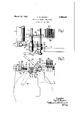
March 22, 1932. c BROWN WHIP ROLL RELEASE FOR LQOMS Filed June 30, 1951 v \nvenTor. Carl D. Brown byWMJ/W ATTys.
Patented Mar. 22,1 1932.
TiES} PATENT oF-F ce CARL D. BROWN, or HQPEDALE, MASSACHUSETTS, ASSIGNOR. To Danna CORPQRATION,
or HorEDALnjMAssAoI-IUsETTs, A CORPORATION OF MAINE wing 'noLLnELnAsE non ooms Application mar June a0,
Looms are universally provided, with an element extendingacross the warp sheet between the warp .beam and'the front of the Y 100m and yieldingly pressed against and de-' fleeting the warp sheet so as to equalize the tension inthe warps during the weaving operation. Such an element is usually embodied in what is known as a whip roll. While such an element is necessaryto the proper weaving of the cloth in a loom ,andfunctions advantageously a'nd efficiently so long as thefloom is running, it frequently produces an inj urious elfect if it remains in pressure-exerting position when theloom it not running. If the loom is left standing even for a short time, as during a pickout orfor a longertime, as when the loom is stopped overnight or over a week-end, the pressure imposed by such an element as the whip roll upon and deflecting the warp sheet, particularly where rayon and such fibres are employed, acts to produce stretching and a more: or less permanent set in the warps and toleavea mark in the finished woven cloth. The stretching of the warps and the'marking of the cloth thus effected is highly undesirable and frequently destroys the commercial value of long pieces of cloth or renders them salable only as seconds. Y y
' In acompanion applicationrof Draper and Kearsley, SerialNo. 547,818, filed'June 30, 1931, manually operated means are provided enabling the operator, whenever theloom is stopped for any reason, to release the pressure exerted by the element, such asthewhip roll,
and. to induce the movement ofthis element away from the warp sheet whereby any such defects in the cloth are avoided. f g
The object of the present invention is to provide manually operated means fora similar purpose acting to secure the desired result by moving the element, itself, such as the whip roll, to a position. where its pressure on the -wa'rpsheet is released. 1 i
V More specifically the invention has-forits 0b ect provide manually operated means for a similar purpose in connectionfwith a whip roll journalled in arms projecting from a whip roll shaftiand also in connection with such a whip roll construction wherein the 1931. Serial No. 547,816.
[whip -roll shaft is loom frame.
The object of the'invention is further to .provide means acting to stop the loom immediately if the loomis started withthe whip roll or other similar element'in pressure released position. I 7
Theseand other obj ectsand features of the 'inventioniwill appear more fully from the accompany in'g description and drawings and will be particularly pointed out in the claims.
Since the, invention relates to but one. feature of a loom and since the general construction and operation of looms are well known and familiar to those skilled in the-art, it is onlyfnecessary here to illustrate and describe thosefeatures with which a preferred embodiment*;,of the inventionv is particularlyconw ed? 1 Inthe drawings:
' Fig. 1 is a top'plan view. of a portion of I the rear end of a loom sufiicient to illustrate a simple and preferred embodiment of the in-, vention;
I Fig. 2 is a side elevation of the construction shown in Fig. 1.
" Only a portionof one of the side frames 1 mounted to slide .on' the and only the construction at one side ofithe loom is shown. It will be understood thatthe construction at the opposite sideisthe same so far as the mounting and ournallin'g of the various shafts and parts are concerned.
In this type of construction the whiproll shaft 2 is journalled at each end in a bean,
ing' in a block 3 mountedto slide forward and rearward of the loom on the slightly inclinedgui'de plate 4 projecting from the side frame of the loom. This whip roll shaft has adjustably secured thereto, at each end, as by a set screw 5, a rearwardly pro ect1ng arm 6. The whip roll '7 has its trunnions 8 journalled in these arms. The whip roll shaft 2 has secured thereto the usual downwardly projecting arm indicated in dotted lines 9 by which-the whip roll shaft'is con- F nected to a suitable let-off mechanism. The 7 action of these let-ofi' mechanisms being well known and familiar, it is unnecessary to ilplustrateor describe them, but it will be 'remembered that, through the usual connec frame.
tions therewith the arm such as 9 holds the whip roll shaft so as to cause the whip roll to press yieldingly against and deflect the warp sheet in its passage from the warp beam to the front of the loom and that in In the preferred embodiment of this in vention an operating shaft 12 is journalled in the loom frame in parallelism with the whip roll shaft and forward thereof. A toggle connection is provided between the whip roll shaft and this operating shaft. This toggle connection is shown as comprising a bifurcated arm 13 journalled on the shaft 2 and an arm 14 secured by the set screw 15 to the-shaft 12'with'its free end projecting between the bifurcations of the arm 13. The free ends of the arms 13 and 14 are pivoted together by the pivotal connection 16..
An operating handle 17 is secured to one endof the shaft 12 by means of which the shaft may be rotated or osoillatedbetween a position in which the whip roll isheld in normal'working position and a position in which the whip-roll is released from tensionapplying position on the warp sheet; A The parts are shown inthe drawings in full lines in the former position, a position which may 7 be determined by engagement of the arm 13 with a lug 18 projecting from the loom The parts are shown in the second position in dotted lines in Fig. 2 and this position is determined by engagement of the bearing block 3 with an adjustable stop shown as "a set screw 19 threaded into and projecting from the loom frame above the guide plate 4. I
lVith the parts in normal position, the whip roll is held yieldingly against the warp sheet and acts in the usual manner to main-- tain'the required tension in the warp sheet.
In this position the toggle connection is straightened out, thus, locking the bearings for the whip roll shaft against movement on the guide plates 4. I
If the loom is stopped and left standing even for short periods as during a pick-out, and particularly for longer periods, as overnight or for a week-end, the pressure of the whip roll against the warp sheetacts to produce a permanent set in the warps and unduly to stretch the warps, particularly inthe case of delicate yarns and yarns of rayon which take a permanent set when stretched. The present invention enables the operator eration moves the whip roll and the springs or otheryielding means forcing the whip roll against the warp sheet bodily in a direction away from the warp sheet and to a position where the pressure of the whip roll on the Warp sheet is removed and thus the tension on the'warps released. Owing to the toggle typeof connection employed, there is no tendency of the whip roll to return to its operative position and it is necessary for the operator to rotate the handle back to its normal position in order for the whip roll again to berendered operative in its pressure-exertingposition.
There isthus presented a very simple and effective means by which the operator may manually and positively shift the whip roll when the 100111 is stopped to a position where it can exert no pressure on the Warp sheet. Thus all danger of injury to the warps or defects in the cloth due to the loom standing with the whip roll pressing against the warp sheet is obviated. Thepresent invention presents a further feature inthat it provides means for preventing the loombeing started and operated with the whip roll in pressure released position whichmight happen through oversight on the part of the operator. For this purpose the invention makes use of one of the loom stopping means with which looms are commonly "provided. The invention provides means which actswhen the whip roll is moved to inoperative pressure-releasing position to renderthis loom stopping means active so that if the 100m is started with the whip roll in pressure releasing position, it will immediately be stopped by the action of the loom stopping means.
7 The particular loom stopping means here illustrated is a warp stop motion of a familiar type indicated generally at 20. In this mechanism the warps support drop wires 21 mounted over relatively endwise reciprocating serrated bars 22. If a warp breaks, its drop wire falls and locks the corresponding serrated bars 22 against relative reciprocation and this event is utilized to stop the loom all in a well known and familiar manner.
In the present invention an element such as a finger 23 is secured to the whip roll shaft 2 and projects rearwardly therefrom. Normally this finger stands in a position such as shown in full lines in the drawings. But when the operator shifts the operating handle 17 and moves the parts to the position I where the tension in .www
ing the handle 17 and consequently the whip roll and the finger 23 to normal position, the loom will immediately be stopped through the action of the warp stop motion because the finger 23 will be functioning in the same manner as the fallen drop wire.
Having thus described the invention, what is claimed asnew, and desired to be secure by Letters Patent, is: t I
1. In a loom a whip roll shaft,arms extending therefrom, a whip roll journalledin said arms, means associated therewith acting yieldingly to press the whip roll against the warp sheet after it leaves thewarp beam, an-
operating shaft, a handle for manually rotating the operating shaft, and a connection between the said shafts acting when the operating shaft is in one rotary position to maintain the whip roll in its operative position to equalize the tension in thewarps during the weavingoperation and, when the operating shaft is in another rotary position to retain the whip roll in a position where the tension in the warps is released; t 2. In a loom having the construction defined in claim 1, a loom stopping means, an
means controlled by the movement of the, op- I erating shaft to its second position to render the loom stopping means active to stop the loom immediately if started with the whip roll in released position; i
3. In a loom having the construction defined in claim 1, a warp stop motion controlled by drop wires, and an element operated by the movement of the operating shaft to its second position to have the same effect on the warp stop motion as a fallen drop wire, thereby to cause the loom to be stopped immediately if started with the whip roll in released position.
4. In a loom, a whip roll, springs assoclated with the whip roll normally acting yieldingly to press the whip roll against the warp sheet after it leaves the warp beam to equalize the tension in the warps during the weaving operation and manually operated means for bodily moving the whip roll to a position the warps is released.
5. In a loom, a whip roll shaft, armsextending therefrom, a whip roll journalled in said arms, bearings for the whip, roll shaft mounted to slide on the loom frame, anoperating shaft journalled'in the 100m frame in I parallelism withthewhip roll shaft, a toggle 6 connection betweensaid shafts normally actalreadystopped. Butv if later on acting means warp sheet andto a position inwhich the from the pressure of hold the bearings and the whiproll ing to means for manually in working position, and rotating the operating the loom frame position where its pressureonthe warp sheet is released. 7 I
6. Ina loom, an element extending across theiwarp sheet between the warp beam and against and deflecting the warp sheet to equalize'the tension in the warps during the weaving operation, manually operated means for moving the said element to aposition ;to release-its pressure on the warp I stoppingmeans, and means controlled by the movement of said element to its releasing position to render the loom stopping means activeto stop the loom, immediately if started with the said element in released position; I
I 7. In a loom, an elementextending across the warp sheet between the warp beam and the front of the 100m, means acting yieldingly to press the saidelement against andito defleet the warp sheet to'equalize the tensionin the weaving operation,
the warps during manually operated means for shifting bodily both the said element and the saidyieldingly in a direction, away from the warp sheet is released the said element, loom 7 stopping means, and means controlled bythe shift of the said element to pressure releasing position to stopthe loom immediately if started with the said element in pressure releasing position. I
8. In a loom, an element extending across the warp sheet between the warp beamand the front of the loom. yieldingly pressed against and deflecting the warp sheet to equalsheet, loom q shaft to break the toggle connection and slide the bearings on to move'the whip rollto a ize the tension in the warps during the weaving operationand manually operated means for movingthe said element to a position to release its pressure on the warp sheet.
9. In a loom, an element extending across the warp sheet between the warp beam and the front of the loom, means acting yieldingto press the said element against and to y deflect the warp sheet to equalize the tension in the warps during the weaving operation, and manually operated means movable to shift the said element bodilyaway from its normal pressure exerting position, thereby to release the tension in the warps. I
10. In a loom, an element extending across the warp sheet between the'warp beam and the front of the loom, means acting yieldingly to press the said element against and to deflect the warp sheet to equalize the tension in'the warps during the weaving operation, and-manually operated means movable in one direction to shift :the said element bodily away from its normal pressure exerting position, thereby to release the tension in the warps, and movable in the opposite direction the front of the loom'yieldingly pressed toshift the said element bodily backto its said normal position. e g
11. In a loom, an element extending across the warp sheet between the warp beam and the front of the loom, means acting yieldingly to press the said element against and to deflect the warp sheet to equalize the tension in the warps during the weaving operation and manually operated means for shifting bodily both the said element and the said yieldingly acting means ina direction away from the warp sheet andv to a position in which the Warp sheet is released fromthe pressure of the said element.
12. In a loom,an element extending across the warp sheet between the warp beam and the front of the loom, means acting'yielding- I 1y to press the said element against and to deflect the warp sheet to equalize the tension in the warps during the weaving operation and manually operated means for shifting bodily vboth the said element and the said yieldingly'acting means in a direction away from the warp sheet and to a position in which thewarp sheet is released from the pressure of the said element and for shifting bodily both the said elementand thesaid means in the opposite direction to restorethem to normal position.
In testimony whereof, I name to this specification.
CARL n; BROWN.
have signed my
Priority Applications (1)
| Application Number | Priority Date | Filing Date | Title |
|---|---|---|---|
| US547816A US1850125A (en) | 1931-06-30 | 1931-06-30 | Whip roll release for looms |
Applications Claiming Priority (1)
| Application Number | Priority Date | Filing Date | Title |
|---|---|---|---|
| US547816A US1850125A (en) | 1931-06-30 | 1931-06-30 | Whip roll release for looms |
Publications (1)
| Publication Number | Publication Date |
|---|---|
| US1850125A true US1850125A (en) | 1932-03-22 |
Family
ID=24186247
Family Applications (1)
| Application Number | Title | Priority Date | Filing Date |
|---|---|---|---|
| US547816A Expired - Lifetime US1850125A (en) | 1931-06-30 | 1931-06-30 | Whip roll release for looms |
Country Status (1)
| Country | Link |
|---|---|
| US (1) | US1850125A (en) |
Cited By (1)
| Publication number | Priority date | Publication date | Assignee | Title |
|---|---|---|---|---|
| US2667773A (en) * | 1951-08-14 | 1954-02-02 | Alfred Hofmann & Co | Warp tensioning bar for knitting machines |
-
1931
- 1931-06-30 US US547816A patent/US1850125A/en not_active Expired - Lifetime
Cited By (1)
| Publication number | Priority date | Publication date | Assignee | Title |
|---|---|---|---|---|
| US2667773A (en) * | 1951-08-14 | 1954-02-02 | Alfred Hofmann & Co | Warp tensioning bar for knitting machines |
Similar Documents
| Publication | Publication Date | Title |
|---|---|---|
| US1850125A (en) | Whip roll release for looms | |
| US3258038A (en) | Weft end cutting devices for shuttleless looms | |
| US4112981A (en) | Device for feeding pile warp yarns for pile fabric looms | |
| US1629849A (en) | Loom | |
| US2095840A (en) | Loom | |
| US2502735A (en) | Loom with stationary weft supply | |
| US650717A (en) | Take-up mechanism for looms. | |
| US1739232A (en) | Let-off for looms | |
| US1715962A (en) | Loom temple | |
| US607377A (en) | hutchins | |
| US789283A (en) | Stopping means for looms. | |
| US2147602A (en) | Loom | |
| US357711A (en) | -hutohins | |
| US1850300A (en) | Whip roll release for looms | |
| US1758738A (en) | Let-off mechanism for looms | |
| US804964A (en) | Crack-preventing means for looms. | |
| US1398532A (en) | Stop mechanism for looms | |
| US1520274A (en) | Double-pile-fabric loom | |
| US1643417A (en) | Let-off mechanism for looms | |
| US1799995A (en) | Thin-place preventer for looms | |
| US1628815A (en) | Balanced let-off for looms | |
| US604632A (en) | Thread-cutting temple for looms | |
| US1500466A (en) | Loose reed for looms | |
| US649242A (en) | Warp stop-motion for looms. | |
| US19073A (en) | Island |