US1850124A - Automatic time and valve controlling apparatus for yarn dyeing and washing machines - Google Patents
Automatic time and valve controlling apparatus for yarn dyeing and washing machines Download PDFInfo
- Publication number
- US1850124A US1850124A US372555A US37255529A US1850124A US 1850124 A US1850124 A US 1850124A US 372555 A US372555 A US 372555A US 37255529 A US37255529 A US 37255529A US 1850124 A US1850124 A US 1850124A
- Authority
- US
- United States
- Prior art keywords
- valve
- motor
- dyeing
- electric
- switch
- Prior art date
- Legal status (The legal status is an assumption and is not a legal conclusion. Google has not performed a legal analysis and makes no representation as to the accuracy of the status listed.)
- Expired - Lifetime
Links
- 238000005406 washing Methods 0.000 title description 19
- 238000009970 yarn dyeing Methods 0.000 title description 6
- 238000004043 dyeing Methods 0.000 description 21
- 239000007788 liquid Substances 0.000 description 16
- 235000010627 Phaseolus vulgaris Nutrition 0.000 description 4
- 244000046052 Phaseolus vulgaris Species 0.000 description 4
- 238000004804 winding Methods 0.000 description 2
- 238000010276 construction Methods 0.000 description 1
- 239000013256 coordination polymer Substances 0.000 description 1
- 238000010586 diagram Methods 0.000 description 1
- 239000012530 fluid Substances 0.000 description 1
- 239000011810 insulating material Substances 0.000 description 1
- 239000000463 material Substances 0.000 description 1
- 230000002441 reversible effect Effects 0.000 description 1
- 238000009991 scouring Methods 0.000 description 1
Images

Classifications
-
- D—TEXTILES; PAPER
- D06—TREATMENT OF TEXTILES OR THE LIKE; LAUNDERING; FLEXIBLE MATERIALS NOT OTHERWISE PROVIDED FOR
- D06B—TREATING TEXTILE MATERIALS USING LIQUIDS, GASES OR VAPOURS
- D06B5/00—Forcing liquids, gases or vapours through textile materials to effect treatment, e.g. washing, dyeing, bleaching, sizing impregnating
- D06B5/12—Forcing liquids, gases or vapours through textile materials to effect treatment, e.g. washing, dyeing, bleaching, sizing impregnating through materials of definite length
- D06B5/16—Forcing liquids, gases or vapours through textile materials to effect treatment, e.g. washing, dyeing, bleaching, sizing impregnating through materials of definite length through yarns, threads or filaments
Definitions
- Patented ar. 22, 19352 CHARLES E. BEAN, F STAFFORD SPRINGS, CONNEGTICUE AUTOMATIC TIME AND VALVE CONTROLLING APPARATUS FOR YARN DYEHTG m WASHING MAC'HINES Application filed Tune 21, 1929. Serial No. 372,555. I
- This invention relates to improvements in an automatic time and valve controlling apparatus for yarn dyeing and washing machines.
- the invention further comprises means for accurately timing the flow in opposite directions of these two liquids through the spools- At the present time it requires the attention and services of at least two persons and a helper for operating each vat.
- the present invention is, therefore, designed to automatically control the dyeing and washing operation of several vats at the same time. This is accomplished by means of electrical circuits and switches which will be fully described.
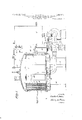
- Fig. 1 is a sideelevation partly in section of one of the dyeing and washing vats, showa ing one of the spools and yarn thereon in section, also the pipe and pump connections;
- Figs. 2 and 3 are detail sectional views of the control valves of the vats;
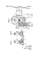
- Fig. his a plan view ofthe mechanism for operating the control valvesand the elec-.
- Fig. 5 is a plan view of the'electrical tim:
- Fig. 6 is a side view of Fig. 5;
- Fig. 7 shows the wiring diagram of the electrical connections.
- 1 designates the vat in which the spools 2 are placed. These spools are formed with a hollow perforated core 3 having the opening 4. -5 is a rod which extends through the core for securing the spools 2 in place in the vat. This rod extends through the opening 6 in the floor "e 7 of the vat. 8 is a compartment between the floor 7 and lower floor or bottom 9. 10 are the supporting legs. A suitable cover 11 is secured to the top of the vat. 12 is the usual expansion tank which is connected to the top of the vat with thepipes 13 and 14. 15 is a pipe leading from the-bottom of the tank 12 to a circulating pump 16 which is connected by means of the pipe 17 to the bottom of the valve casing 18.
- a pipe 19 Extending from the valve casing is a pipe 19 that opens into the compartment 8. nother pipe 2(lshown in Fig. 1 also opens into this compartment. This pipe is directly behind the pipe 19. Located on the top of the valve casing 18 is a plate 21 on 75 which is placed an electric motor 22 which operates the worm 23 that drives the worm gear or, wheel 24 to which the link 25 is connected, at one end and to the valve arm 26,
- This motor drives the two worms 34- and 35 which operate the wormgears 36 and 37.
- 38 and 39 are two sprocket chains which drive the worms 40 and 41 and these, in turn,-rotate the worm gear wheels 42 and 43.
- the gear-.42 as stated above, may be considered as the washing gear and the gear'43 as the dyeing gear.
- the speed of gear 43 may ofcourse, be changed by changing the size of the sprocket wheel 37'.
- the gear 42 has secured thereto the switch operating member 108 44 which engages the arm 45 of the member 46 which slides in the supports 47, and 48. 49 is a coiled spring which is located in the slotted arm 48.
- This spring actuates a ball 50 which bears against the slidable member 46 to force it into locking engagement with the arm 48 when moved downward by 44.
- the slot in the arm 48 is indicated at 48.
- the member 45 is notched at 46.
- a coiled spring 51 normally draws the slidable member 46 upward to close the electric contacts 52 and open the electric contacts 53.
- The' contacts 52 are'electrically connected to the wire 54 and the line wire 33;
- the electric contacts 53 are connected to the wire 56 and line wire 33.
- the worm gear43 operates to control the j current in the wires 63 and 64 in the same manner as the worm gear 42.
- the gear 43 which is termed the dyeing gear is provided with switch operating devices 65 and 66 for operating the slidable member 67 in the same way as the slidable member 46 is operated by switch operating devices 44 and 45 on the gear. 42.
- the switch operating device 66 is adjustable while the device 65 is fixed.
- FIG. 7 3 is a projection that is engaged by switch operating device 65 to move the slidable member 67 upward against the tension of the spring 67
- Contacts 74 are connected to the wire 75 and contacts 76 are connected to the wire 77 which lead to the poles 78' and 79 respectively of the switch 62 which closes the circuit to the wires 63 and 64 when the switch 62 is thrown erating motor 22.
- the switch 62 isvshown thrown to the right. This cuts in worm gear 43 for the dyeing operations. This gear operates the.
- the cam member 66 is formed with a cam face 66 which engages the end of the arm 64 for moving the member 67 outof locking engagement with the arm" 71, in a similar manner as that already described for the member 46, whereby the spring 67 will break the contacts at 74 and close them at 74".
- Curved slots 66'. are provided for adjusting the member 66.and cam face 66' for varying the line of in and outflow of the dyeing liquid.
- a member 90 Slidably mounted in'the extensions 89 bf the bracket 80 is a member 90 having insulating material at its ends, as shown, for separating and insulating the spring contacts 83 and 84 from each other when it is moved .in opposite direction by means of the adjustable steps 91 and 92 on the arms 93 and 94 of the oscillating valve 27.
- the plate 95 is secured to the valve 27 and iskoperated with the valve 27 by the arm 26 from the electric motor 22 by means of which, the adjustable stops 91 and 9-2 engage in turnihe'projection 96 of the slidable member 90 for opening and closing the electric circuits at the contacts 8 and 84., V
- the operation may be described as follows:
- the electric motor 32 may be considered as operating continuously to drive the two worm gears 42 and 43.
- the switch 62 is in the position shown to close the circuits to the line the pipe 19 and return through pipe 20.
- valve 27 closes the circuit the valve operating motor 22, which, through the worm 23, wheel 24, link 25, and arm 26, rotates the valve 27 until the adjustable stop 91 engages the projection 96 and shifts the movable member 90, thereby opening contacts 83, stopping the motor 22 and closing the contacts 84.
- Valve 27 has thus been reversed and the liquid flows in the opposite direction through the yarn for five minutes.
- the constantly rotating wfiorm wheel 42 opens contact 53 and closes contact 52. This is caused by the cam face of member 45 on wheel 42 forcin back arm 64 of the bell crank 64, causing the face 64 thereof to press against 46 and release it from engagement with slot 48', whereupon the spring 51 pulls 46 upward, breaking contact 58 and closing contact 52.
- each one of the vats 1 is controlled by a separate switch 62 tion, or, any one or more may be in use.
- wash-' ing wherever used in the description, that the generally accepted word for such operations is scouring.
- a flow reversing valve in the connections, means for operatlng the valve, and means for timing the operations of the valve operating means.
- a dyeing and washing apparatus having in combination with a vat member, pipe connections for circulating the liquid therethrough, anoscillating valve in the pipe connections for changing the direction of the flow of the liquid through the vat, an electric motor for operating the valve, an electromagnetic switch means for opening the circuit to the motor, switch devices operated by the motor for controlling the current to connections for changing the direction of flow of the liquid, an electric motor, aworm and worm gear driven by the motor, crank and link connection between the valve and the worm gear, switch operated means connected to the valve for stopping the motor, a line wire, and timing means between the line wire and the electric motor switch operated means for starting the motor and for predetermining the length of time the said valve is in its different positions for changing the direction of flow either into or from the vat. 6.
- a dyeing and washing apparatus having in combination with a plurality of vats, pipe connections for each vat for directing the liquid into and from the vat, valves for changing the direction of flow of the liquid in the vats, a separate timing device for the dyeing and washing, means for operating each.timing device, a power line, electric switches operable from each timing device, electric motors for operating the valves electrical connections between the electric switches and the electric motors, and switch means operable by the electric motors for breaking the electrical connections and preparing for other connections to be made.
- said automatic means comprising a driven member, a pair of switches operated by and from the driven member, means on the driven member for determining the period of time at which the pair of switches are operated, andelectrical connections between the pair of switches and the circuit to the electric motor which operates the reversing valve.
Landscapes
- Engineering & Computer Science (AREA)
- Chemical & Material Sciences (AREA)
- Materials Engineering (AREA)
- Textile Engineering (AREA)
- Treatment Of Fiber Materials (AREA)
Description
932, c. E. BEAN AUTOMATIC TIME AND VALVE CONTROLLING APPARATUS FOR YARN DYEING AND WASHING MACHINES File'd June 21, 1929 4 Sheets-Sheet l g? aw/ail: 221? A TTORNE Y.
March 22, 1932. c. E. BEAN 1,350,124
AUTOMATIC TIME AND VALVE CONTROLLING APPARATUS FOR YARN DYEING AND WASHING MACHINES Filed June 21, 1929 4 Sheets-Sheet 2 INVENTOR,
' with,
ATTORNEY.
March 22, 1932. c. E. BEAN 1,850,124
AUTOMATIC TIME! AND VALVE CONTROLLING APPARATUS FOR YARN DYEING AND WASHING MACHINES Filed June 21, 1929 4 Sheets-Sheet 3 I, i N I 63-' I M 52 64 i 5 6% D O v 4/ O T 453 CP a c 0r 7 '6 0': )yezky 1 a 3 v c 0 7g" 5 v if 6' :1] w
a'z 5 %z%= 13; 6/ 4% ,49 44 a; H? m 4/ I a; p w x -66 I j M w 1 3 a: 51 G ii I H v INVENTOR, Czarlesfifimn,
BY 4U A TTORNEY.
March 22, 1932. I BEAN 1,850,124
AUTOMATIC TIME AND VALVE CONTROLLING APPARATUS FOR YARN DYEING AND WASHING MACHINES Filed June 21, 1929 4 Sheets-Sheet 4 VA W 32 INVENTOR, flalkslffiswa.
w waww A TTORNEY.
Patented ar. 22, 19352 CHARLES E. BEAN, F STAFFORD SPRINGS, CONNEGTICUE AUTOMATIC TIME AND VALVE CONTROLLING APPARATUS FOR YARN DYEHTG m WASHING MAC'HINES Application filed Tune 21, 1929. Serial No. 372,555. I
This invention relates to improvements in an automatic time and valve controlling apparatus for yarn dyeing and washing machines.
At the present time it is the common practice to cause the dyeing solution, or liquid, to be forced through the yarn in one direction and then, after a definite interval of time, to cause the dyeing and washing liquids to be m forced through the yarn in the opposite direction. This is accomplished by winding the yarn on a spool formed with a hollow core having perforations therethrough. These spools with the wound yarn thereon are mounted in a vat, or container, the bottom of which is formed with openings over which the open lower ends of the hollow cores of the yarn wound spools are placed. Below this bottom is a compartment which is termed a false bottom that is in communication with pipe and pump connections for forcing the dyeing and washing fluid in opposite directions through the hollow cores and through the windings or layers" of yarn in pppdsite directions.
The invention further comprises means for accurately timing the flow in opposite directions of these two liquids through the spools- At the present time it requires the attention and services of at least two persons and a helper for operating each vat. The present invention is, therefore, designed to automatically control the dyeing and washing operation of several vats at the same time. This is accomplished by means of electrical circuits and switches which will be fully described.
Referring to the drawings: Fig. 1 is a sideelevation partly in section of one of the dyeing and washing vats, showa ing one of the spools and yarn thereon in section, also the pipe and pump connections; Figs. 2 and 3 are detail sectional views of the control valves of the vats;
.Fig. his a plan view ofthe mechanism for operating the control valvesand the elec-.
trical switch connections;
, Fig. 5 is a plan view of the'electrical tim:
ing mechanism for the dyeing and washing 50 operations;
. at its other end, as shown in plan view in Fig.
Fig. 6 is a side view of Fig. 5; and
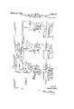
Fig. 7 shows the wiring diagram of the electrical connections.
Referring to the drawings in detail: 1 designates the vat in which the spools 2 are placed. These spools are formed with a hollow perforated core 3 having the opening 4. -5 is a rod which extends through the core for securing the spools 2 in place in the vat. This rod extends through the opening 6 in the floor "e 7 of the vat. 8 is a compartment between the floor 7 and lower floor or bottom 9. 10 are the supporting legs. A suitable cover 11 is secured to the top of the vat. 12 is the usual expansion tank which is connected to the top of the vat with thepipes 13 and 14. 15 is a pipe leading from the-bottom of the tank 12 to a circulating pump 16 which is connected by means of the pipe 17 to the bottom of the valve casing 18. Extending from the valve casing is a pipe 19 that opens into the compartment 8. nother pipe 2(lshown in Fig. 1 also opens into this compartment. This pipe is directly behind the pipe 19. Located on the top of the valve casing 18 is a plate 21 on 75 which is placed an electric motor 22 which operates the worm 23 that drives the worm gear or, wheel 24 to which the link 25 is connected, at one end and to the valve arm 26,
8-0 4. This construction oscillates the two-way valve 27, as shown in Figs. 2 and 3. Attached. to the liquid reversing valve 27 is an indicator rod 28 carrying a pointer 29 which indicates the position of the valve 27. 63 and 64 designate the wires from the main line to the motor 22 in which is located the switch 62 for each vat. 32 designates an electric motor which is electrically connected to the line wires 33.
This motor drives the two worms 34- and 35 which operate the wormgears 36 and 37. 38 and 39 are two sprocket chains which drive the worms 40 and 41 and these, in turn,-rotate the worm gear wheels 42 and 43. The gear-.42, as stated above, may be considered as the washing gear and the gear'43 as the dyeing gear. The speed of gear 43, may ofcourse, be changed by changing the size of the sprocket wheel 37'. The gear 42 has secured thereto the switch operating member 108 44 which engages the arm 45 of the member 46 which slides in the supports 47, and 48. 49 is a coiled spring which is located in the slotted arm 48. This spring actuates a ball 50 which bears against the slidable member 46 to force it into locking engagement with the arm 48 when moved downward by 44. The slot in the arm 48 is indicated at 48. The member 45 is notched at 46. A coiled spring 51 normally draws the slidable member 46 upward to close the electric contacts 52 and open the electric contacts 53. The' contacts 52 are'electrically connected to the wire 54 and the line wire 33; The electric contacts 53 are connected to the wire 56 and line wire 33. Contacts 52 are electrically connected to the wire 58 and the pole 59 of the switch 62-and contacts 53 are connected to wire 60 and switch pole 61 of the double throw switch 62 which poles are electrically The worm gear43 operates to control the j current in the wires 63 and 64 in the same manner as the worm gear 42. The gear 43 which is termed the dyeing gear is provided with switch operating devices 65 and 66 for operating the slidable member 67 in the same way as the slidable member 46 is operated by switch operating devices 44 and 45 on the gear. 42. The switch operating device 66 is adjustable while the device 65 is fixed. They are so spaced on the worm 43 so as to time the dyeing operations for four minutes in flow, indicated as In 4 and out seven minutes a indicated at Out 7 and the radial lines 68 and 69 for example. The member 67 slides in the arms 70 and 71. A notch 72 and spring and ball 73 is employed to move the notch 72 into locking engagement with the slotted arm 71 in the same manner as described for the worm gear 42. 7 3 is a projection that is engaged by switch operating device 65 to move the slidable member 67 upward against the tension of the spring 67 Contacts 74 are connected to the wire 75 and contacts 76 are connected to the wire 77 which lead to the poles 78' and 79 respectively of the switch 62 which closes the circuit to the wires 63 and 64 when the switch 62 is thrown erating motor 22. In, Fig. 7 at the right hand end, the switch 62 isvshown thrown to the right. This cuts in worm gear 43 for the dyeing operations. This gear operates the.
In Fig; 5 the cam member 66 is formed with a cam face 66 which engages the end of the arm 64 for moving the member 67 outof locking engagement with the arm" 71, in a similar manner as that already described for the member 46, whereby the spring 67 will break the contacts at 74 and close them at 74". Curved slots 66'. are provided for adjusting the member 66.and cam face 66' for varying the line of in and outflow of the dyeing liquid.
Located on the valve casing 18 see Fig.
4) is a contact supporting member 80 and secured to the. valve casing by means of the bracket arms 81 and 82. 83 and 84 are pairs of spring contact arms which normally close together. Wire 63 isconnected to one of the contact arms of 84 and 64 is connected to one of the contact arms 83.
Slidably mounted in'the extensions 89 bf the bracket 80 is a member 90 having insulating material at its ends, as shown, for separating and insulating the spring contacts 83 and 84 from each other when it is moved .in opposite direction by means of the adjustable steps 91 and 92 on the arms 93 and 94 of the oscillating valve 27. The plate 95 is secured to the valve 27 and iskoperated with the valve 27 by the arm 26 from the electric motor 22 by means of which, the adjustable stops 91 and 9-2 engage in turnihe'projection 96 of the slidable member 90 for opening and closing the electric circuits at the contacts 8 and 84., V
The operation may be described as follows: The electric motor 32 may be considered as operating continuously to drive the two worm gears 42 and 43. The switch 62 is in the position shown to close the circuits to the line the pipe 19 and return through pipe 20. At
the termination of the out flow period of five minutes the member 44 moves the slidable member 46 downward, or towards the observer as shown in Fig. 5. This operation opens the electric contacts 52 and closes the electric contacts 53. The slidable member 46 is now locked in this position by means of the notch 46' in the slotted arm 48 by action of the spring 49 and ball50. Current now, flows by thewire 56, contacts 53, wire 60, switch 62, wire 63, contacts 84, wire 97 to the solenoid operated or magneti switch 98 wire 99 to the. line wires 33. Th'
closes the circuit the valve operating motor 22, which, through the worm 23, wheel 24, link 25, and arm 26, rotates the valve 27 until the adjustable stop 91 engages the projection 96 and shifts the movable member 90, thereby opening contacts 83, stopping the motor 22 and closing the contacts 84. Valve 27 has thus been reversed and the liquid flows in the opposite direction through the yarn for five minutes. At the end of that period the constantly rotating wfiorm wheel 42 opens contact 53 and closes contact 52. This is caused by the cam face of member 45 on wheel 42 forcin back arm 64 of the bell crank 64, causing the face 64 thereof to press against 46 and release it from engagement with slot 48', whereupon the spring 51 pulls 46 upward, breaking contact 58 and closing contact 52. This closes the circuit to motor 22, through wires 58 and 64, contact 84, wire 97, and electro-magnetic switch 98, and the motor proceeds to revolve switch 62 is opened. 101 is a brake device for the motor 22. The magnetic brake 101 acts on the motor 22 to stop its revolutions immediately upon the breaking of the circuit to-the motor, thereby preventing the gear'24 from overrunning, and thus maintaining the link 25 and link 27 in proper position to hold the valve 26 in either of its operative positions.
When the switch 62 is thrown towards the J right hand the dyeing worm wheel 43 is put into operation in the same manner as the ivorm wheel 42 but with the adjustable timing members 65 and 66 so arranged as to cause the in flow for a period of, say four minutes and the out flow for seven minutes as indicated by the radial lines'68 and 69.
It is to be understood that each one of the vats 1 is controlled by a separate switch 62 tion, or, any one or more may be in use.
The full anddotted arrows 100 and 101 in Fig. 1 indicate the How and return of the washing and dyeing liquids.
It is to be understood by the term wash-' ing, wherever used in the description, that the generally accepted word for such operations is scouring.
What I claim is:
1-. In an apparatus of the kind described, in combination with a driven member, means operated by the driven member for alternately opening and closing a pair of electric switches, a pump, a vat, pipe connections between the vat and the pump, a valve in the pipe connections, an electric motor for operating the valve, electric connections between the electric switches and the electric motor, and means operated by the motor for breaking the electric connections to the motor,
2. In an apparatus of the kind described, in combination with a driven member, means operated by the driven member for alternately opening and closing a pair of electric switches, a pump, a vat, pipe connections v between the vat and the pump, a valve in the pipe connections, an electric motor for operating the valve, electric connections between the electric switches and the electric motor, and means operated by the motor for breaking the electric connections to the motor, and comprising a part secured to the valve, a movable member reciprocally operated by said part, and contacts for the purpose of stopping the motor by the movable member for operating the contacts.
3. In a dyeing and washing apparatus in combination with a vat member having inlet and outlet pipe connections, a flow reversing valve in the connections, means for operatlng the valve, and means for timing the operations of the valve operating means.
4. A dyeing and washing apparatus having in combination with a vat member, pipe connections for circulating the liquid therethrough, anoscillating valve in the pipe connections for changing the direction of the flow of the liquid through the vat, an electric motor for operating the valve, an electromagnetic switch means for opening the circuit to the motor, switch devices operated by the motor for controlling the current to connections for changing the direction of flow of the liquid, an electric motor, aworm and worm gear driven by the motor, crank and link connection between the valve and the worm gear, switch operated means connected to the valve for stopping the motor, a line wire, and timing means between the line wire and the electric motor switch operated means for starting the motor and for predetermining the length of time the said valve is in its different positions for changing the direction of flow either into or from the vat. 6. A dyeing and washing apparatus having in combination with a plurality of vats, pipe connections for each vat for directing the liquid into and from the vat, valves for changing the direction of flow of the liquid in the vats, a separate timing device for the dyeing and washing, means for operating each.timing device, a power line, electric switches operable from each timing device, electric motors for operating the valves electrical connections between the electric switches and the electric motors, and switch means operable by the electric motors for breaking the electrical connections and preparing for other connections to be made.
7. In combination, in a dyeing and washing machine, two timing devices, electric switches operated by the devices, an electric motor, a valve operated by the electric motor for controlling the fiow of the dyeing and washing I liquid to the vat in which the material to be dyed and washed is placed, switch operating means connected to the valve and operated from the same for automatically controlling the circuit to the motor, electrical connections between the timing devices and the motor and means in the connections for putting either the dyeing or washing timing gear into operation. p
, 8. In a dyeing and washing apparatus, the combination with a vat and pipe connections therefor, a reversible valve in the pipe con- Y nections, an electric motor for operating the valve, electrical connections to the motor, a
separate timing device for determining the time of the in or out flow of the two liquids through the vat, a switch in the connections for cutting in or out each timing device, and switch operated means in the connections which are controlled by the electric motor for breaking the currentbetween the timing 'device and the motor. 1 I 9. In combination with a'v'at having pipe connections theretoand a reversing valve in the pipe connections, an electric motor for 5 operating the valve, an electric circuit to the motor, means operated by motor and simultaneously with the valve for opening the electric circuit to the motor, and automatic means for timing the duration of flow of the liquid in the vat in one direction, and .for timing it in an opposite direction.
10. In combination with a vat having pipe connections thereto and a reversing valve in the pipe connections,'an electric motor for' operating the valve, an electric circuit to the motor, means operated by motor and simultaneously with the valve for opening the duration of the flow of the liquid in the vat in onedirection, and for timing it in an opposite direction, said automatic means comprising a driven member, a pair of switches operated by and from the driven member, means on the driven member for determining the period of time at which the pair of switches are operated, andelectrical connections between the pair of switches and the circuit to the electric motor which operates the reversing valve.
CHARLES E. BEAN.
electric circuit to the motor and assuming a position for the closing of another circuit to the motor, an automatic means'for timing the
Priority Applications (1)
| Application Number | Priority Date | Filing Date | Title |
|---|---|---|---|
| US372555A US1850124A (en) | 1929-06-21 | 1929-06-21 | Automatic time and valve controlling apparatus for yarn dyeing and washing machines |
Applications Claiming Priority (1)
| Application Number | Priority Date | Filing Date | Title |
|---|---|---|---|
| US372555A US1850124A (en) | 1929-06-21 | 1929-06-21 | Automatic time and valve controlling apparatus for yarn dyeing and washing machines |
Publications (1)
| Publication Number | Publication Date |
|---|---|
| US1850124A true US1850124A (en) | 1932-03-22 |
Family
ID=23468642
Family Applications (1)
| Application Number | Title | Priority Date | Filing Date |
|---|---|---|---|
| US372555A Expired - Lifetime US1850124A (en) | 1929-06-21 | 1929-06-21 | Automatic time and valve controlling apparatus for yarn dyeing and washing machines |
Country Status (1)
| Country | Link |
|---|---|
| US (1) | US1850124A (en) |
Cited By (5)
| Publication number | Priority date | Publication date | Assignee | Title |
|---|---|---|---|---|
| US2582601A (en) * | 1947-04-18 | 1952-01-15 | Palik Frank | Multiple liquid processing container |
| US2586244A (en) * | 1948-01-16 | 1952-02-19 | William E J Mcmann | Apparatus for controlling the flow of dye liquor through kiers |
| US2957332A (en) * | 1957-12-24 | 1960-10-25 | Coop Norman Dennis | Washing, mixing and like machinery |
| WO2001048296A1 (en) * | 1999-12-24 | 2001-07-05 | Stone Neal C | Low pressure steam jet fabric finisher |
| US20030000022A1 (en) * | 2000-12-22 | 2003-01-02 | Stone Neal C. | Low pressure steam jet fabric finisher |
-
1929
- 1929-06-21 US US372555A patent/US1850124A/en not_active Expired - Lifetime
Cited By (6)
| Publication number | Priority date | Publication date | Assignee | Title |
|---|---|---|---|---|
| US2582601A (en) * | 1947-04-18 | 1952-01-15 | Palik Frank | Multiple liquid processing container |
| US2586244A (en) * | 1948-01-16 | 1952-02-19 | William E J Mcmann | Apparatus for controlling the flow of dye liquor through kiers |
| US2957332A (en) * | 1957-12-24 | 1960-10-25 | Coop Norman Dennis | Washing, mixing and like machinery |
| WO2001048296A1 (en) * | 1999-12-24 | 2001-07-05 | Stone Neal C | Low pressure steam jet fabric finisher |
| US20030000022A1 (en) * | 2000-12-22 | 2003-01-02 | Stone Neal C. | Low pressure steam jet fabric finisher |
| US6895621B2 (en) * | 2000-12-22 | 2005-05-24 | Neal C. Stone | Low pressure steam jet fabric finisher |
Similar Documents
| Publication | Publication Date | Title |
|---|---|---|
| US2265225A (en) | Means and method for purifying liquids | |
| US3464437A (en) | Overflow protection device | |
| US1850124A (en) | Automatic time and valve controlling apparatus for yarn dyeing and washing machines | |
| US2254795A (en) | Valve control mechanism | |
| US2662384A (en) | Washing machine control mechanism | |
| US2608252A (en) | Domestic appliance | |
| GB455438A (en) | Improvements in and relating to dishwashing machines | |
| US1939181A (en) | Reel control device | |
| US1965840A (en) | Centrifugal machine | |
| US2227926A (en) | Circulating system for material treating | |
| US2355455A (en) | Washing machine | |
| US3872694A (en) | Washing machine | |
| US1940549A (en) | Laundering apparatus | |
| US3122009A (en) | Laundry machine | |
| US2612034A (en) | Automatic washing machine with detergent injector | |
| US3648487A (en) | Washer load sensor control | |
| US2946212A (en) | Control system for wash water storage and re-use system | |
| US1780380A (en) | Automatic control system for electric motors | |
| US3140595A (en) | Control circuit for clothes washing machine | |
| GB590899A (en) | Improvements in apparatus for the automatic control of the various stages of the washing process in a washing machine | |
| US3087319A (en) | Clothes washing machine with water level control circuit | |
| US1639368A (en) | Automatic washing machine | |
| US1828822A (en) | Coil winding machine | |
| US2619284A (en) | Thermostatic mixer for washing machines | |
| US2615455A (en) | Apparatus for cleaning watches and watch parts |