US1850117A - Combined check valve and unloader - Google Patents
Combined check valve and unloader Download PDFInfo
- Publication number
- US1850117A US1850117A US222801A US22280127A US1850117A US 1850117 A US1850117 A US 1850117A US 222801 A US222801 A US 222801A US 22280127 A US22280127 A US 22280127A US 1850117 A US1850117 A US 1850117A
- Authority
- US
- United States
- Prior art keywords
- check valve
- valve
- piston
- stem
- port
- Prior art date
- Legal status (The legal status is an assumption and is not a legal conclusion. Google has not performed a legal analysis and makes no representation as to the accuracy of the status listed.)
- Expired - Lifetime
Links
Images
Classifications
-
- F—MECHANICAL ENGINEERING; LIGHTING; HEATING; WEAPONS; BLASTING
- F16—ENGINEERING ELEMENTS AND UNITS; GENERAL MEASURES FOR PRODUCING AND MAINTAINING EFFECTIVE FUNCTIONING OF MACHINES OR INSTALLATIONS; THERMAL INSULATION IN GENERAL
- F16K—VALVES; TAPS; COCKS; ACTUATING-FLOATS; DEVICES FOR VENTING OR AERATING
- F16K15/00—Check valves
- F16K15/02—Check valves with guided rigid valve members
- F16K15/06—Check valves with guided rigid valve members with guided stems
- F16K15/063—Check valves with guided rigid valve members with guided stems the valve being loaded by a spring
-
- Y—GENERAL TAGGING OF NEW TECHNOLOGICAL DEVELOPMENTS; GENERAL TAGGING OF CROSS-SECTIONAL TECHNOLOGIES SPANNING OVER SEVERAL SECTIONS OF THE IPC; TECHNICAL SUBJECTS COVERED BY FORMER USPC CROSS-REFERENCE ART COLLECTIONS [XRACs] AND DIGESTS
- Y10—TECHNICAL SUBJECTS COVERED BY FORMER USPC
- Y10T—TECHNICAL SUBJECTS COVERED BY FORMER US CLASSIFICATION
- Y10T137/00—Fluid handling
- Y10T137/2496—Self-proportioning or correlating systems
- Y10T137/2544—Supply and exhaust type
- Y10T137/2557—Waste responsive to flow stoppage
-
- Y—GENERAL TAGGING OF NEW TECHNOLOGICAL DEVELOPMENTS; GENERAL TAGGING OF CROSS-SECTIONAL TECHNOLOGIES SPANNING OVER SEVERAL SECTIONS OF THE IPC; TECHNICAL SUBJECTS COVERED BY FORMER USPC CROSS-REFERENCE ART COLLECTIONS [XRACs] AND DIGESTS
- Y10—TECHNICAL SUBJECTS COVERED BY FORMER USPC
- Y10T—TECHNICAL SUBJECTS COVERED BY FORMER US CLASSIFICATION
- Y10T137/00—Fluid handling
- Y10T137/2496—Self-proportioning or correlating systems
- Y10T137/2559—Self-controlled branched flow systems
- Y10T137/2574—Bypass or relief controlled by main line fluid condition
- Y10T137/2579—Flow rate responsive
- Y10T137/2582—Including controlling main line flow
- Y10T137/2584—Relief or bypass closes as main opens
-
- Y—GENERAL TAGGING OF NEW TECHNOLOGICAL DEVELOPMENTS; GENERAL TAGGING OF CROSS-SECTIONAL TECHNOLOGIES SPANNING OVER SEVERAL SECTIONS OF THE IPC; TECHNICAL SUBJECTS COVERED BY FORMER USPC CROSS-REFERENCE ART COLLECTIONS [XRACs] AND DIGESTS
- Y10—TECHNICAL SUBJECTS COVERED BY FORMER USPC
- Y10T—TECHNICAL SUBJECTS COVERED BY FORMER US CLASSIFICATION
- Y10T137/00—Fluid handling
- Y10T137/2496—Self-proportioning or correlating systems
- Y10T137/2559—Self-controlled branched flow systems
- Y10T137/2574—Bypass or relief controlled by main line fluid condition
- Y10T137/2579—Flow rate responsive
- Y10T137/2587—Bypass or relief valve biased open
-
- Y—GENERAL TAGGING OF NEW TECHNOLOGICAL DEVELOPMENTS; GENERAL TAGGING OF CROSS-SECTIONAL TECHNOLOGIES SPANNING OVER SEVERAL SECTIONS OF THE IPC; TECHNICAL SUBJECTS COVERED BY FORMER USPC CROSS-REFERENCE ART COLLECTIONS [XRACs] AND DIGESTS
- Y10—TECHNICAL SUBJECTS COVERED BY FORMER USPC
- Y10T—TECHNICAL SUBJECTS COVERED BY FORMER US CLASSIFICATION
- Y10T137/00—Fluid handling
- Y10T137/2496—Self-proportioning or correlating systems
- Y10T137/2559—Self-controlled branched flow systems
- Y10T137/2574—Bypass or relief controlled by main line fluid condition
- Y10T137/2605—Pressure responsive
- Y10T137/2612—Common sensor for both bypass or relief valve and other branch valve
- Y10T137/2615—Bypass or relief valve opens as other branch valve closes
-
- Y—GENERAL TAGGING OF NEW TECHNOLOGICAL DEVELOPMENTS; GENERAL TAGGING OF CROSS-SECTIONAL TECHNOLOGIES SPANNING OVER SEVERAL SECTIONS OF THE IPC; TECHNICAL SUBJECTS COVERED BY FORMER USPC CROSS-REFERENCE ART COLLECTIONS [XRACs] AND DIGESTS
- Y10—TECHNICAL SUBJECTS COVERED BY FORMER USPC
- Y10T—TECHNICAL SUBJECTS COVERED BY FORMER US CLASSIFICATION
- Y10T137/00—Fluid handling
- Y10T137/8593—Systems
- Y10T137/86919—Sequentially closing and opening alternately seating flow controllers
Definitions
- This invention relates to an improved check valve or automatic unloaderto be used with air or other gascompressors, and particularly to a' combined check valve and bleed valve designed to be arranged in a pipe line between an air compressor and receiver for unloading the compressor when thelatter stops running, or operates below a; predeterminedminimum speed;
- the device forming the subject matter of the invention includes a non-pulsating leakproof check valve, operating in the discharge pipe of a compressor, and designed to cooperate with the bleed valve for automatically unloading a portion of the discharge pipe adacent to the compressor, whenever'the, com.- pressor ceases 1ts compressive action or reducesthe same to a predetermined minimum, thereby facilitating the starting of the compressor against pressure in the mains or tanks which the compressor is supplying,fand which are loaded beyond my improved loading device.
- the invention is especially applicable-to a compressor in which the starting and stopping of the motoror engine driving the compressor, is controlledtby electrical or other suitable and usual means.
- the function of the unloader is primarily to provide for unloading during the starting period, and the check valve 3 prevents leakage from the; receiver after the compressor hasceased itsjcompresminimum speed.
- One of the objects ofthe invention is to sive action or is operating below acertain provide an unloader for this purpose, including an oil dash pot of anon-leaking character, andeadapted to cause the check valve to operate without pulsating,;so that the device will be silent in operationand' capable. of-long.
- a further object of the invention is to. prothat apart may be replaced whenever necessary, without discardingthe entire device..
- a still further object is to provide an un-" scribed in detail, illustrated in the accompanyin'gI drawings, and, more particularly pointed out in the appended claims;
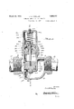
- Fig. 1 is a vertical longitudinal sectional view of my improved device.
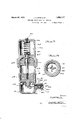
- Fig. 2 is'a transverse vertical sectional view
- Fig.3 is a bottom plan view of the dash pot piston.
- l designates the body or V mainI casing which is provided at one -:side with athreaded connection 2" to be attached to a pipe3 leading from acompressor (not shown).
- the oppositeside of the casing has a similar-threaded connection-4 to be attached to a pipe 5 leading to a compressed air re- CQIlYGT-fIlOli shown).
- I j I Y 7 A7? tubular extension; 6, having external threads projects upwardly from thecasing and is aligned with a cylindrical partition :7, located within the casing, which forms a chamber for the cheick'valve 8.
- the check'valve 8 controls an air inlet port 11 and an outlet port 12, one arranged in the bottom and the other in the side of the chamber 7 and the inlet port being surrounded by a valve seat 13, forming an abutment for ayielding-packing washer 14:, arranged on thelower surface of the check valve 8.
- This packing is secured in positionby meansof a a ,7 l y sis
- the bottom of the cas ng provides ashallow basin 9 into which any sediment coming from washer and a nut 16, both mounted on a threaded. extension 17 at the lower end of the valve.
- the check valve has a threaded connection with the lower end of a valve stem 18 which slides through a cover or partition 19 that fits in the tubular extension 6 of the valve casing, and has a circular flange 20-resting on the upper edge of said tubular-extension.
- the rod slides through a packing 21 inthe partition whichcooperate's with an adjustable gland 22.
- the upper portion of the valve stem has a fixed abutment 23, engag e'able with .the un'der side of a dashpot piston 24.
- This piston has a port 25 at its center, through which the valve stem passes, and this port is of larger diameter than the valve stem to allow oil or the like in a dash *pot chamber 26 to flow through the piston 24 when the latter moves downw ardlyi
- the abutment 23 is .of larger diameter than the port 25, so in order tn allowthe fluid to flow past the abutnient andthrough the port, radial notches 27 are provided the lower face of the dash pot piston.
- the latter is provided at its upper end with an adjustable nut 28 which can only be screwed down to a point where it will.
- l pot chamber 26 is formed within a cap or auxiliary which has its lower .end threaded to the tubular extension 6 .and is provided with an annular shoulder abutting against the fiange' 2O for. sealing purposes.
- the cap 31 has a threaded uppe end, cl ed by a re d P s 5 a d an annular 34 extends into the cap tr omits upper end and surrounds said aper ture.
- the damping liquid is fed into the sap h o h th a ertu a its; l pp ien and the flange 34 forms an indicator which li e'r re erma u e i fi a e 1 4 1 to the lower end of the flange, butnot above this point.
- asmall cushion of air provided to take care of the oil displaced"whenthe piston 24 is first noved upwardly under the iofceof si dm' 'li'w nrr i
- the flange 34 alsoformsaprojectiori, functioning as "an anchoring means for one end of the coil spring theother end of the spring g n i i 3am end-i s tea y force the piston and check valve downwardly.
- the bleed valve casing is provided at one .end an adjustable or rotatable valve seat 39, having a bleed port, 40 extending therethrough, and. provided at its outer end with a cross notch 41 to receive a screwdriver, which may be used to rotate this seat.
- the opposite end" surface of'the valve seat is arranged at: a slight angle to the vertical, as shown at 42, and this surface engages the head 43 of the bleed valve; the latter being forced against the inclined face by a coiled spring 44 which abuts at one end against the flange 38, and at its other end'against the headof the valve.
- the periphery of the valve head is notched as shown at 35, to permit air and sediment to pass by.
- the bleed valve has a stem 46 which eX- tends through the coil spring 44 and the tubular casing 47, and projects beneath the end 17 of the check valve, whereby, as the latter approaches its seat, the valve stem 46 will be rocked and the bleed valve will be opened. It is obvious that by turning the bleed valve seat 39, the annular face 42 will be adjusted, and in this way, the time of opening the bleed valve may also be hurried.
- the bleed valve seat has an annular flange 47 "which slides on the outer end'of the tubular member 47, and is rotatably held in place by a screw cap 48.
- check valve 8 will be held in its upper position by the compressed air travelling through the unloader, but immediately upon the speed falling below said predetermined minimum,
- the present device is of simple and inexpensive construction, and may be easily repaired when the same is necessary. Furthermore, it is apparent that the oil inthe dash pot will be retained in place indefinitely, and need only be renewed or added to, after long periods of operation; and that the device will operate noiselessly and with a minimum of wear.
- a combined check valve and unloader for use with air compressors including a valve casing having an inlet and an outlet, a partition in the casing dividing the interior of the same, into anintake chamber and an outlet chamber, a port in the partition for placing the chambers in communication, a
- check valve in the casing adapted to control theport and ,opening'under fluid pressure admitted through said inlet, a cap on the casing, a second partition separating the interior of the cap from the outlet chamber, a
Landscapes
- Engineering & Computer Science (AREA)
- General Engineering & Computer Science (AREA)
- Mechanical Engineering (AREA)
- Compressor (AREA)
Description
March 22, 1932. J. o. McMlLLAN 1,850,117
COMBINED CHECK VALVE AND UNLOADER Filed-Sept. 29. 1927 2 Sheets-Sheet 1 J0. M /VI'LLAN,
March 22, 1932. 1Q, MCWLLAN 1,850,117
COMBINED CHECK VALVE AND UNLOADER Filed Sept. 29. 1927 2 Sheets-Sheet 2 v P, 62 W ll Q4 9 56 as Zlwuantot JW/Lm/v,
Patented Mar. 22, 1932 PATENT} orsics:
; JAMES O.MCMILLAN,OF1ELDORADO, KANSAS,IASSIGNOR 'ro STANDARD rumr'a sUrrLY comreny; or wrcnrrA, Kansas; jAi CORPORATION or mixes comnrnnnfl'cnncx v-ALvE AND .UNLOADER Application filed September 29,1927, Serial No. 222,801;
V This invention relates to an improved check valve or automatic unloaderto be used with air or other gascompressors, and particularly to a' combined check valve and bleed valve designed to be arranged in a pipe line between an air compressor and receiver for unloading the compressor when thelatter stops running, or operates below a; predeterminedminimum speed;
The device forming the subject matter of the invention includes a non-pulsating leakproof check valve, operating in the discharge pipe of a compressor, and designed to cooperate with the bleed valve for automatically unloading a portion of the discharge pipe adacent to the compressor, whenever'the, com.- pressor ceases 1ts compressive action or reducesthe same to a predetermined minimum, thereby facilitating the starting of the compressor against pressure in the mains or tanks which the compressor is supplying,fand which are loaded beyond my improved loading device.
The inventionis especially applicable-to a compressor in which the starting and stopping of the motoror engine driving the compressor, is controlledtby electrical or other suitable and usual means. The function of the unloader is primarily to provide for unloading during the starting period, and the check valve 3 prevents leakage from the; receiver after the compressor hasceased itsjcompresminimum speed. p 7
- One of the objects ofthe invention is to sive action or is operating below acertain provide an unloader for this purpose, including an oil dash pot of anon-leaking character, andeadapted to cause the check valve to operate without pulsating,;so that the device will be silent in operationand' capable. of-long.
V wear.
vide the unloader with a relatively shallow sediment chamber, which will be. automatically evacuated when the check valve operates to open the bleed valve. I V
'A still further object is to furnisha device of this character,-formed of a'number' of parts detachably connectedtogether, .so
A further object of the invention is to. prothat apart may be replaced whenever necessary, without discardingthe entire device..
A still further object is to provide an un-" scribed in detail, illustrated in the accompanyin'gI drawings, and, more particularly pointed out in the appended claims;
Referring tothe drawings,
Fig. 1 is a vertical longitudinal sectional view of my improved device. i
Fig. 2 is'a transverse vertical sectional view,
taken on line 2--2 of Fig, 1.
Fig.3 is a bottom plan view of the dash pot piston. In the drawings, ldesignates the body or V mainI casing which is provided at one -:side with athreaded connection 2" to be attached to a pipe3 leading from acompressor (not shown). The oppositeside of the casinghas a similar-threaded connection-4 to be attached to a pipe 5 leading to a compressed air re- CQIlYGT-fIlOli shown). I j I Y 7 A7? tubular extension; 6, having external threads projects upwardly from thecasing and is aligned with a cylindrical partition :7, located within the casing, which forms a chamber for the cheick'valve 8.
surface lOof the partition 7,: and this sediment will be blown out of the casing through the bleed valve opening hereinafter described.- v
The check'valve 8 controls an air inlet port 11 and an outlet port 12, one arranged in the bottom and the other in the side of the chamber 7 and the inlet port being surrounded by a valve seat 13, forming an abutment for ayielding-packing washer 14:, arranged on thelower surface of the check valve 8. This packing is secured in positionby meansof a a ,7 l y sis The bottom of the cas ng provides ashallow basin 9 into which any sediment coming from washer and a nut 16, both mounted on a threaded. extension 17 at the lower end of the valve.
The check valve has a threaded connection with the lower end of a valve stem 18 which slides through a cover or partition 19 that fits in the tubular extension 6 of the valve casing, and has a circular flange 20-resting on the upper edge of said tubular-extension. The rod slides through a packing 21 inthe partition whichcooperate's with an adjustable gland 22. I g
The upper portion of the valve stem has a fixed abutment 23, engag e'able with .the un'der side of a dashpot piston 24. This piston has a port 25 at its center, through which the valve stem passes, and this port is of larger diameter than the valve stem to allow oil or the like in a dash *pot chamber 26 to flow through the piston 24 when the latter moves downw ardlyi It will be noted that the abutment 23 is .of larger diameter than the port 25, so in order tn allowthe fluid to flow past the abutnient andthrough the port, radial notches 27 are provided the lower face of the dash pot piston. Toloosely hold the piston on thevalve stem, the latter is provided at its upper end with an adjustable nut 28 which can only be screwed down to a point where it will.
allow a clearance 29 between the nut and piston as the piston moves upwardly. A relatively small hole 30 extends through the pistonto permit the liquid in the dash pot to slowly feed through the piston, as the piston moves downwardly, for at this time, the nut 28 will have closed the, port 25.
The cap 31 has a threaded uppe end, cl ed by a re d P s 5 a d an annular 34 extends into the cap tr omits upper end and surrounds said aper ture. The damping liquid is fed into the sap h o h th a ertu a its; l pp ien and the flange 34 forms an indicator which li e'r re erma u e i fi a e 1 4 1 to the lower end of the flange, butnot above this point. When the cap has been filled to this extent, asmall cushion of air provided to take care of the oil displaced"whenthe piston 24 is first noved upwardly under the iofceof si dm' 'li'w nrr i The flange 34 alsoformsaprojectiori, functioning as "an anchoring means for one end of the coil spring theother end of the spring g n i i 3am end-i s tea y force the piston and check valve downwardly.
It l l v b s s as th Be sel h s dual function, the most important one of aperture at its vided with. internal annular flange 38.
The bleed valve casing is provided at one .end an adjustable or rotatable valve seat 39, having a bleed port, 40 extending therethrough, and. provided at its outer end with a cross notch 41 to receive a screwdriver, which may be used to rotate this seat. The opposite end" surface of'the valve seat is arranged at: a slight angle to the vertical, as shown at 42, and this surface engages the head 43 of the bleed valve; the latter being forced against the inclined face by a coiled spring 44 which abuts at one end against the flange 38, and at its other end'against the headof the valve. The periphery of the valve head is notched as shown at 35, to permit air and sediment to pass by. the bleed valve head, and to discharge through the port 40 The bleed valve has a stem 46 which eX- tends through the coil spring 44 and the tubular casing 47, and projects beneath the end 17 of the check valve, whereby, as the latter approaches its seat, the valve stem 46 will be rocked and the bleed valve will be opened. It is obvious that by turning the bleed valve seat 39, the annular face 42 will be adjusted, and in this way, the time of opening the bleed valve may also be hurried.
The bleed valve seat has an annular flange 47 "which slides on the outer end'of the tubular member 47, and is rotatably held in place by a screw cap 48.
In operation, air from the compressor will enter the end 2 of the unloader casing, and when a sufficient pressure has been built up in the casing, the check valve 8 will be lifted 011 its seat. As it rises, its movement will be. cushioned by the dash pot, for at this time, the quick upward movement of the piston 24 will force the oil aboveth e piston upwardly, and will be compensated'for by the air cushion at the upper end of the cap 81. At the same time, and continuing thereafter, oil will flow through the port 25 and notches 27 and through the hole 30, into the lower portion of the upper portion of the chamber 26 is of larger diameter than the lower portion of the same, and consequently, provides a larger space for oil and eliminates a certain amount of machine work. 7
As the check valve rises, the spring 44 of the bleed valve will seat the latter, and close the bleed port 40, so that air will only leak 7 through the latter for a relatively short time during the raising of the' ch'eckvalve 8.
As long as the compressor'is operating above a. predetermined minimum speed, the
check valve 8 will be held in its upper position by the compressed air travelling through the unloader, but immediately upon the speed falling below said predetermined minimum,
or upon the stopping of the compressor, the,
spring will begin to seat the check valve 8. This operation will be slower, however,
than the opening of the check valve, for as the piston moves downwardly, the nut 28 will close the port 25, and then the only passage for the oil is by way of the small hole 30. As the check valve moves downwardly, its lowerend 17 will rock the bleed valve stem 46, and thus open the port i0, so that any air in the pipe 3, connection 2 or basin 9, may readily escape through said port, At the same time, the force of the air will blow any sediment past the bleed valve, and out through the port.
It will be obvious to those skilled in the art, without further description, that the present device is of simple and inexpensive construction, and may be easily repaired when the same is necessary. Furthermore, it is apparent that the oil inthe dash pot will be retained in place indefinitely, and need only be renewed or added to, after long periods of operation; and that the device will operate noiselessly and with a minimum of wear.
I am aware that changes may be made in the details disclosed, without departing from the spirit of the invention as expressed in the claims. I
What I'claim and desire to secure by Let and an oil dash pot structure for cushioning the movement of the check valve in'either direction, said oil dash pot structure in eluding a stem having spaced abutments thereon, a piston movable axially on the stem between said abutments and havinga port through which the stem passes,.one of said abutments functioning to close the port when the stem is moved in one direction, said pis ton having a relatively: small hole spaced from the axis of the stem a greater distance than the periphery ofeitherofsaid abutments to permit the oil to flow through the piston and detachably connected to said check valve,
a cap detachably connected to the valve casing, holding the second partition in position and with the latter, forming a dash pot cham= her, abutments on the stem and arranged I within the dash pot chamber, a piston axial- 1y movable on the stem and engageable with the abutments, ports in the, piston through which oil may pass, one ofsaid ports being controlled by one of said abutments, a spring exerting its force against the stem for clos-V ing the check valve, and a bleed valve controlled by the check valve and functioning to evacuate one of the chambers of the valve casing.
3. A combined check valve and unloader for use with air compressors, including a valve casing having an inlet and an outlet, a partition in the casing dividing the interior of the same, into anintake chamber and an outlet chamber, a port in the partition for placing the chambers in communication, a
check valve in the casing adapted to control theport and ,opening'under fluid pressure admitted through said inlet, a cap on the casing, a second partition separating the interior of the cap from the outlet chamber, a
stem secured to said valve and sliding.
through the second partition, spaced abutments arranged on the stem within the cap, a piston loosely mounted on the stem between said abutments and having centrally disposed openings to permit oil to flow along the stem through the piston when the latter is moving upwardly, notches in the piston .extendingfrom the openings to thelower' surface of the piston to permit oil to flow through the openings even though the lower one of said abutments is pressing against the under surface of the piston, a small port extendingthrough the piston at a distance from the stem greater than the periphery of either of said abutments, a spring in the ca'p bearing on one of said abutments, Vfor closing the check valve, and a bleed valve for the intake chamber controlled by .the
check valve. JAS. OLMQMILLAN.
CERTIFICATE. OF CORRECTION.
Patent No. 1,850,117. Granted March 22, 1932, to
JAMES 0. McMILLAN.
It is hereby certified that the name of the assignee in the above numbered patent was erroneously described and specified as "Standard Pump 81 Supply Company", whereas saidname should have been described and specified as Air-O-Matic Manufacturing Company, as shown by the records of assignments in this office; and that the said Letters Patent should be read with this correction therein that the same may conform to the record of the case in the Patent Office.
Signed and sealed this 7th day of June, A. D. 1932.
M. J. Moore, (Seal) Acting Commissioner of Patents.
Priority Applications (1)
| Application Number | Priority Date | Filing Date | Title |
|---|---|---|---|
| US222801A US1850117A (en) | 1927-09-29 | 1927-09-29 | Combined check valve and unloader |
Applications Claiming Priority (1)
| Application Number | Priority Date | Filing Date | Title |
|---|---|---|---|
| US222801A US1850117A (en) | 1927-09-29 | 1927-09-29 | Combined check valve and unloader |
Publications (1)
| Publication Number | Publication Date |
|---|---|
| US1850117A true US1850117A (en) | 1932-03-22 |
Family
ID=22833735
Family Applications (1)
| Application Number | Title | Priority Date | Filing Date |
|---|---|---|---|
| US222801A Expired - Lifetime US1850117A (en) | 1927-09-29 | 1927-09-29 | Combined check valve and unloader |
Country Status (1)
| Country | Link |
|---|---|
| US (1) | US1850117A (en) |
Cited By (13)
| Publication number | Priority date | Publication date | Assignee | Title |
|---|---|---|---|---|
| US2500806A (en) * | 1946-07-19 | 1950-03-14 | American Brake Shoe Co | Valve |
| US2634947A (en) * | 1948-01-06 | 1953-04-14 | Lawrence H Gardner | Flow control valve |
| US2667894A (en) * | 1944-02-17 | 1954-02-02 | Electraulic Presses Ltd | Pressure relief valve with damping piston |
| US2695627A (en) * | 1951-10-19 | 1954-11-30 | Gen Electric | Weight loaded pressure reducer |
| US2735643A (en) * | 1956-02-21 | Throttle return check | ||
| US2805681A (en) * | 1952-03-18 | 1957-09-10 | Ingersoll Rand Co | Pressure relief valve |
| US2993505A (en) * | 1953-06-06 | 1961-07-25 | Electraulic Presses Ltd | Relief valve |
| US3064675A (en) * | 1960-02-08 | 1962-11-20 | Fisher Governor Co | High pressure regulator |
| DE2608791A1 (en) * | 1975-03-03 | 1976-10-14 | Yarway Corp | MODULATING FLOW CONTROL VALVE ARRANGEMENT |
| US4535967A (en) * | 1984-01-05 | 1985-08-20 | Joy Manufacturing Company | Expanding gate valve with fluid-powered actuator |
| US5234482A (en) * | 1990-12-27 | 1993-08-10 | Haldex Ab | Retarding valve at a single-tower air drier |
| US6564877B1 (en) | 2000-12-01 | 2003-05-20 | Class 1, Inc. | Automatic valve with manual override for fire engine high pressure water system |
| US20040007261A1 (en) * | 2002-07-12 | 2004-01-15 | Cornwell James P. | Check valve |
-
1927
- 1927-09-29 US US222801A patent/US1850117A/en not_active Expired - Lifetime
Cited By (15)
| Publication number | Priority date | Publication date | Assignee | Title |
|---|---|---|---|---|
| US2735643A (en) * | 1956-02-21 | Throttle return check | ||
| US2667894A (en) * | 1944-02-17 | 1954-02-02 | Electraulic Presses Ltd | Pressure relief valve with damping piston |
| US2500806A (en) * | 1946-07-19 | 1950-03-14 | American Brake Shoe Co | Valve |
| US2634947A (en) * | 1948-01-06 | 1953-04-14 | Lawrence H Gardner | Flow control valve |
| US2695627A (en) * | 1951-10-19 | 1954-11-30 | Gen Electric | Weight loaded pressure reducer |
| US2805681A (en) * | 1952-03-18 | 1957-09-10 | Ingersoll Rand Co | Pressure relief valve |
| US2993505A (en) * | 1953-06-06 | 1961-07-25 | Electraulic Presses Ltd | Relief valve |
| US3064675A (en) * | 1960-02-08 | 1962-11-20 | Fisher Governor Co | High pressure regulator |
| DE2608791A1 (en) * | 1975-03-03 | 1976-10-14 | Yarway Corp | MODULATING FLOW CONTROL VALVE ARRANGEMENT |
| US4535967A (en) * | 1984-01-05 | 1985-08-20 | Joy Manufacturing Company | Expanding gate valve with fluid-powered actuator |
| US5234482A (en) * | 1990-12-27 | 1993-08-10 | Haldex Ab | Retarding valve at a single-tower air drier |
| US6564877B1 (en) | 2000-12-01 | 2003-05-20 | Class 1, Inc. | Automatic valve with manual override for fire engine high pressure water system |
| US20040007261A1 (en) * | 2002-07-12 | 2004-01-15 | Cornwell James P. | Check valve |
| WO2004008011A1 (en) * | 2002-07-12 | 2004-01-22 | R. Conrader Company | Check valve |
| US6698446B2 (en) * | 2002-07-12 | 2004-03-02 | R. Conrader Company | Check valve |
Similar Documents
| Publication | Publication Date | Title |
|---|---|---|
| US1850117A (en) | Combined check valve and unloader | |
| US2223699A (en) | Check valve | |
| US1710635A (en) | Valve | |
| US1655729A (en) | Flush valve | |
| US1961599A (en) | Valve | |
| US2604905A (en) | Flush valve | |
| US2620741A (en) | Pressure responsive valve and valve system | |
| US1789388A (en) | Combined check valve and unloader | |
| US420155A (en) | Self-closing cock or faucet | |
| US1171085A (en) | Flushometer. | |
| US2275132A (en) | Discharge valve | |
| US3754567A (en) | Ball lock control valve | |
| US2624362A (en) | Flow valve for fluid lift pumps | |
| US3530874A (en) | Valves | |
| US959397A (en) | Gas-controlling device. | |
| US1717022A (en) | Combination stop and check valve | |
| US2271274A (en) | Valve | |
| US1809419A (en) | Valve | |
| US2061938A (en) | Method and apparatus for compressing gas | |
| US3405647A (en) | Flow valves | |
| US1990194A (en) | Metering faucet | |
| US1517594A (en) | Pneumatic pump | |
| US1443690A (en) | Flushing valve | |
| US671717A (en) | Self-closing valve. | |
| US193800A (en) | Improvement in valves for water-closets |