US1850116A - Hoisting mechanism - Google Patents
Hoisting mechanism Download PDFInfo
- Publication number
- US1850116A US1850116A US408482A US40848229A US1850116A US 1850116 A US1850116 A US 1850116A US 408482 A US408482 A US 408482A US 40848229 A US40848229 A US 40848229A US 1850116 A US1850116 A US 1850116A
- Authority
- US
- United States
- Prior art keywords
- spool
- brake
- driving
- applying
- shaft
- Prior art date
- Legal status (The legal status is an assumption and is not a legal conclusion. Google has not performed a legal analysis and makes no representation as to the accuracy of the status listed.)
- Expired - Lifetime
Links
- 230000007246 mechanism Effects 0.000 title description 15
- 230000003578 releasing effect Effects 0.000 description 12
- 238000004804 winding Methods 0.000 description 9
- 241000239290 Araneae Species 0.000 description 2
- 150000001768 cations Chemical class 0.000 description 2
- 238000010276 construction Methods 0.000 description 2
- 241000896693 Disa Species 0.000 description 1
- ATJFFYVFTNAWJD-UHFFFAOYSA-N Tin Chemical compound [Sn] ATJFFYVFTNAWJD-UHFFFAOYSA-N 0.000 description 1
- 230000000295 complement effect Effects 0.000 description 1
- 229920000136 polysorbate Polymers 0.000 description 1
- 239000007858 starting material Substances 0.000 description 1
Images
Classifications
-
- B—PERFORMING OPERATIONS; TRANSPORTING
- B66—HOISTING; LIFTING; HAULING
- B66D—CAPSTANS; WINCHES; TACKLES, e.g. PULLEY BLOCKS; HOISTS
- B66D1/00—Rope, cable, or chain winding mechanisms; Capstans
- B66D1/26—Rope, cable, or chain winding mechanisms; Capstans having several drums or barrels
-
- B—PERFORMING OPERATIONS; TRANSPORTING
- B66—HOISTING; LIFTING; HAULING
- B66D—CAPSTANS; WINCHES; TACKLES, e.g. PULLEY BLOCKS; HOISTS
- B66D2700/00—Capstans, winches or hoists
- B66D2700/01—Winches, capstans or pivots
- B66D2700/0125—Motor operated winches
- B66D2700/0166—Winches with multiple drums or with drums with multiple parts of different diameter
Definitions
- the winding spool 2 which is considered as the rear spool, and its associated parts and the operating mechanism therefor, willonly be described.
- the operating mechanism and associatedpartso f the forward winding spool 3 is identical with that of the rear spool 2 and therefore the ordinals employed to desig-V. nate the various parts of the mechanism associated with spool 2 will be given prime marks and applied to the corresponding elements of themechanism associated with spool 3.
- the spool 2 has one terminal portion thereof formed into a brake drum 23, upon which is mounted the brake band 24, and this brake band with its associated drum will through out the description be referred to as the service brake.
- Theother terminal port1on of the spool 2 is provided with a brake drum which has suitably mounted thereon a brake.
- one end 27 of the service brake band 24 is secured by the pin 28 rigidly mounted in the base 1 and the other e-nd29 thereof is supported by the pin 30 rigidly mounted in the member 31 which is secured to the revoluble shaft '32, which is journaled in the side of the base 1.
- Rigidly secured to the shaft 32 is a member 33 which has rigidly united therewith the end 34 of the foot lever35, which carries the foot pad 36.
- the safety brake band 26 is rigidly secured at one end 37 thereof, and the other end 38.0f the band 26 is secured by means of the pin 39 to the member 40 which is secured to the shaft thereby effecting a greater contact area be-f tween the band 26 and the drum 25.
- a crank arm 42 Rigidly mounted on the shaft 41 is a crank arm 42 which, at its lower end, is adapted to receive the pin 43 by which the rod 44 is attached thereto.
- the rod 44 shown more clearly in Fig. 9, passes through a sleeve 46, which in turn projects through the aperture 47 formed therefor'in the sill 48 on thebase 1 and which is secured to the sill 48 more or less loosely by means of the bolts 49.
- CoaXially mounted with the rod 44 is a thimble 50 which Positioned adjacent one end of the base.
- a thimble 52 secured to the shaft 44 by means of the nut 45.
- a spring bushing 53 is provided between the thimbles 50 and 52 and coaxially mounted on therod 44.
- the rod 44 is provided with a toothed segment 58 which is adapted to en gage the gear 59, which is more clearly shown
- the shaft 60 has frictionally mounted thereon a gear 61 by means of a spring 62, which gear 61 intermeshes with the pinion 63 which is mounted on .the motor shaft 64.
- the shaft 32 has rigidly mounted thereon the arm 65 which carries a pin 66 engaged by the slotted end 67 of the rod 68.
- the rod 68 "The other end of the rod 68 is pivotally mounted on the cam element 72.
- the cam element 72 is pivotally supported at 73 and has ri idly secured thereto the actuating lever 7 4 ,gecured to the rigidly mounted plate 75 is a'switch 76 of the common type, by means of which the current to the torque motor 64.
- the switch 76 has a control lever 77 extending therefrom which carries a frictionless roller 78, which roller is held in contactiwith the surface of the cam 72 by means of a spring switch 7 6.
- Thespool 2, as shownin Fig. 1 is revolubly mounted on the shaft 5 by means of the journal boxes 80 which carry the friction reducing bearings 81 which run on the hardened sleeves 82, which sleeves are spaced apart by means ofthe sleeve'83 carried by the medial portion of the shaft 5.
- CoaXially mounted on the shaft 5 is a gear wheel 84 which is positioned adj acent the collar 85 formed integrally with the shaft 5.
- the gear Wheel 84 has secured thereto a member 86 by means of the bolts 87, which loosely pass througliapert-ures formedtherefor in the web of the gear wheel 84 and which carry locked nuts 88.
- a spring 90 Positionedintermediately of the member 86 and the hub 89 of the gear wheel 84 is a spring 90. l
- the right-hand journal box 80 is provided with a thrust plate 91 secured thereto by means of the bolts 92, and which is adapted to contact with the member 86.
- gear wheel84 carries friction blocks 93 which are adapted to'engage with the complementary beveled faces .94 formed on the spool 2.
- Frictional driving communication between receives its rotation from the pinion 95 (not shown) in the the safety brake must, for the proper func-. tioning, of the hoisting device, be in no way dependable upon the actuation of the service brake.
- the release of the safety brake upon the establishment of driving communication with the spool 2 is eflected by the mechanism clearly illustrated in Figs. 7 .and 8.
- VVhenthe thrust pin 100 is moved axially of the shaft 5 in the hole 101 provided therefor, the end of'the thrust pin forces the cross key 102 againstthe thrust collar 104, which bears against the disk 105, which in turn bears against the surface 106 of the spool 2.
- the disk 105 is free to move relatively, both to'the thrust collar 10 1 and the spool 2, except when" frictionally engaged by these members as a result of pressure on thrust pin 100.
- the friction thrust mechanism is operated, as is the case when a load is being raised by the spool 2, disk l05will turn with the spool 2.
- the disk 105 is stationary upon the shaft 5.
- the tension of the springs 120 will be so adjustedthat the brake shoes 111 and 112 will have sufiicient frictional engagement with the surface of the flange 107 to cause the lever arm to rotate the' shaft 21 ag'ainst the resistance of the spring 51.
- the slot in the rear end of the rod 44 permits the mechanism just described to release the safety brake without having to move the torque motor and also permits the spring 51 to reset the safety brake when the friction mechanism is released without the drag of the torque motor. This con struction reduces the necessary friction between the brakeshoes 111 and 112-and the V at all times and is absolutely independent in its effectiveness from the current by which the hoisting mechanism is actuated.
- the construction as described permits a flexibility of operation of the various parts which has not been possible with mechanisms of like character previously employed.
- erable means for effecting driving communication between said spool and said driving means, a brake associated with said spool and operable means for applying said brake, the combination of a second brake associated with said spool, resilient means for normally applying said second named brake, and means functionally responsive to manipulation of said'first named brake for releasing such last named brake,
- a hoisting machine having a winding spool, means for driving said spool, operable means for effecting driving communication between said spoolan'd said driving means, a brake associated with said spool 1 and. operable'means for applying said brake, the combination of a second brake associated with said-spool, resilient means for normally applying said second named brake, and electrically actuated means functionally ,responsive to manipulation of saidfirst named brake for releasing such last named brake.
- a hoisting machine havinga winding spool, means for driving said spool, operable means for efi'ectingdriving;communication between said spool and said driving means, a brake associated with'said spool and operable means for applying said brake, the combination of a second brake associated applying said second named brake, and
- able means for effecting driving com niin ca inwa sa a bra a oc ted w j'ase sp aan qnemb e means i 11 p-Fly n a dibsak
- a Wi hasaid 19601 nes i s t me n ft nnq m 1y pply ngam d-ascen seem brak an means itriction l y dr v n-tram sa d sp l.
- said spool in a single direction for releasing said second namedrbrakev the mb nati niq' M -9 d,bi ke'a s ciat o wi h said spqolw iesili ntgm ans i 17 eermal y 5.
- brakaand means ing spool, means for driving said spool, op'-.
- a brake associated with said spool and operable means for applying said brake the SPQOl QDIQQIlIS, f combination :of a second brake associated] with said spool, resilient means for normally, applying said second named brake, means functionally responsive to rotation of said spool in a single direction for releasing said I second named brake,and means functionally ,ibrakeaas ooiated; saidspoohloresilient responsive to manipulation of said first named brake for releasing said second named 6,
- a hoisting machine having: a winding spool, means for driving said spool,oper+ able means for effecting driving communication between-said spool and said driving means, a brake associated with said spool and operable meansfor applying said brake,
- a hoisting machine having a winding spool, means fordriving said spool, operable means for. efiecting driving communication between said spool and said driving means, a service brake associated with said spool, and operable means for applying said service brake, the combination of a safety brake associated with said spool, resilient means" for normally applying said safety brake, means frictionally driven by said spool,
- a hoisting machine having a winding spool, means for driving said spool, opera- 'ble'means for effecting driving communication between said spool and said driving means, a servlce brake associated with'said spool, and operable means for applying said service brake, the combination of a, safety brake associated with said spool, resilient means for normally applying said safety brake, means frictionally driven by said spool,
- a hoisting machine having a winding spool, means for driving said spool,
Landscapes
- Engineering & Computer Science (AREA)
- Mechanical Engineering (AREA)
- Braking Arrangements (AREA)
Description
HOISTING MECHANISM Filed Nov. 20. 1929 4 s ets-sh t 1 1NVENTOR .7571 F. 777 Gi/ferf 4w) By 02d JiBerZZ (gay. 6% 1 cfw A TTORNEY March 22, 1932. R, McGlFFERT ET AL 1,850,116
HOISTING MECHANISM Filed Nov. 20. 92 '4 Sheets-Sheet 2 I N VEN TORJ .707: 72,. 772" 62' ife/i 4d BY dla 05.36113? A TTORNEY5.
March 22, 1932. J. RYMCGIFFERT ET AL I 1,850,116
HOISTING MECHANISM Filed NOV. 20, 1929 4 Sheets-Sheet 5 INVENTORD .755 7?. 77 (WY/(ff By 024 of. .2367 52/ ATTORN Y6 March 22, 1932.
J. R. M GIFFERT ET AL 1,850,116
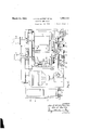
HOISITING MEChANISM Filed Nov. 20. 1929 45heets-Sheet 4 m \x 25 I09 94 84 H5 I08 96 INVENTOR6 Jbizn IT. 777- 627/02 fw ATTORNEYS 13 and 14 and has secured to its terminal portion a crank handle 15 by which the shaft 10 is rotated and the controller 9 properly actuated. frame 1 and rigidly secured thereto is a motor housing frame structure 16, upon which is mounted the resistor units 17 and 18,.and to the sides of which are secured the starter boxes 19 and 20, which are here shown'provided with three-phase A. C. binding postsQl and 22, respectively. 7 i
For the purpose of the-following description the winding spool 2, which is considered as the rear spool, and its associated parts and the operating mechanism therefor, willonly be described. The operating mechanism and associatedpartso f the forward winding spool 3 is identical with that of the rear spool 2 and therefore the ordinals employed to desig-V. nate the various parts of the mechanism associated with spool 2 will be given prime marks and applied to the corresponding elements of themechanism associated with spool 3. The spool 2 has one terminal portion thereof formed into a brake drum 23, upon which is mounted the brake band 24, and this brake band with its associated drum will through out the description be referred to as the service brake. Theother terminal port1on of the spool 2 is provided with a brake drum which has suitably mounted thereon a brake.
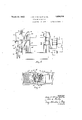
Referring now to Fig. 3, one end 27 of the service brake band 24 is secured by the pin 28 rigidly mounted in the base 1 and the other e-nd29 thereof is supported by the pin 30 rigidly mounted in the member 31 which is secured to the revoluble shaft '32, which is journaled in the side of the base 1. Rigidly secured to the shaft 32 is a member 33 which has rigidly united therewith the end 34 of the foot lever35, which carries the foot pad 36.
V The safety brake band 26 is rigidly secured at one end 37 thereof, and the other end 38.0f the band 26 is secured by means of the pin 39 to the member 40 which is secured to the shaft thereby effecting a greater contact area be-f tween the band 26 and the drum 25.
Rigidly mounted on the shaft 41 is a crank arm 42 which, at its lower end, is adapted to receive the pin 43 by which the rod 44 is attached thereto. The rod 44, shown more clearly in Fig. 9, passes through a sleeve 46, which in turn projects through the aperture 47 formed therefor'in the sill 48 on thebase 1 and which is secured to the sill 48 more or less loosely by means of the bolts 49. CoaXially mounted with the rod 44 is a thimble 50 which Positioned adjacent one end of the base.
1 in Fig; 4 mounted on the'shaft- 60.
is held against the end of the sleeve 46 by means of the spring 51, which at its other end is axially restrained by a thimble 52 secured to the shaft 44 by means of the nut 45. Intermediately of the thimbles 50 and 52 and coaxially mounted on therod 44 is a spring bushing 53. The rod 44 isprovided with a toothed segment 58 which is adapted to en gage the gear 59, which is more clearly shown The shaft 60 has frictionally mounted thereon a gear 61 by means of a spring 62, which gear 61 intermeshes with the pinion 63 which is mounted on .the motor shaft 64.
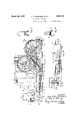
The shaft 32 has rigidly mounted thereon the arm 65 which carries a pin 66 engaged by the slotted end 67 of the rod 68. The rod 68 "The other end of the rod 68 is pivotally mounted on the cam element 72. The cam element 72 is pivotally supported at 73 and has ri idly secured thereto the actuating lever 7 4 ,gecured to the rigidly mounted plate 75 is a'switch 76 of the common type, by means of which the current to the torque motor 64.
is controlled. The switch 76 has a control lever 77 extending therefrom which carries a frictionless roller 78, which roller is held in contactiwith the surface of the cam 72 by means of a spring switch 7 6.
Thespool 2, as shownin Fig. 1 is revolubly mounted on the shaft 5 by means of the journal boxes 80 which carry the friction reducing bearings 81 which run on the hardened sleeves 82, which sleeves are spaced apart by means ofthe sleeve'83 carried by the medial portion of the shaft 5. CoaXially mounted on the shaft 5 is a gear wheel 84 which is positioned adj acent the collar 85 formed integrally with the shaft 5. The gear Wheel 84 has secured thereto a member 86 by means of the bolts 87, which loosely pass througliapert-ures formedtherefor in the web of the gear wheel 84 and which carry locked nuts 88. Positionedintermediately of the member 86 and the hub 89 of the gear wheel 84 is a spring 90. l The right-hand journal box 80 is provided with a thrust plate 91 secured thereto by means of the bolts 92, and which is adapted to contact with the member 86. The
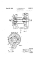
gear wheel84 carries friction blocks 93 which are adapted to'engage with the complementary beveled faces .94 formed on the spool 2. Frictional driving communication between receives its rotation from the pinion 95 (not shown) in the the safety brake must, for the proper func-. tioning, of the hoisting device, be in no way dependable upon the actuation of the service brake. The release of the safety brake upon the establishment of driving communication with the spool 2 is eflected by the mechanism clearly illustrated in Figs. 7 .and 8. VVhenthe thrust pin 100 is moved axially of the shaft 5 in the hole 101 provided therefor, the end of'the thrust pin forces the cross key 102 againstthe thrust collar 104, which bears against the disk 105, which in turn bears against the surface 106 of the spool 2. The disk 105 is free to move relatively, both to'the thrust collar 10 1 and the spool 2, except when" frictionally engaged by these members as a result of pressure on thrust pin 100. When, therefore, the friction thrust mechanism is operated, as is the case when a load is being raised by the spool 2, disk l05will turn with the spool 2. At any time other than when the spool 2 is driven for hoisting the load the disk 105 is stationary upon the shaft 5. 'On the disk 105 an axially extending circumferential flange 107 is provided and on this flange are mounted the brake shoes 111 and 112, to which are secured the brake lining 115 and 116. The proper adjustment of-the brake shoes 111 and 112 is obtained bymeans of the lock nuts 121 and the springs 120 which are coaxially mounted on the bolts-119. The spider 108,
which engages the brakeshoes 111 and 112 in the apertures 118 and 114:, respectively, by means ofthe arm '109 and 110, is loosely mounted with respectto theshaft 5' and rotates' with the disk 105 through the frictional engagement of the brake shoes ylllarid 112 with the flange107.- y
When driving communication has been established between the driving wheel 84: and spool2 in the manner just described the spider 108 will be rotated and will carry therewith the associated links 12 1 and 126, and which in turn cause'a rotation of the shaft ll. The counter-clockwise rotation of the" spool 2, as indicated by the arrow in Fig. 8, and which is the rotation necessary to wind the hoisting cable on the drum as the load suspended thereby is being elevated, will cause the links 124 and 126 V to assume the position shown in dotted lines in Fig. 8'. In moving from, the full'line position to the dotted line position in this figure the shaft 41 will be rotated ,in counter-clockwise direction and the rod 4 1, which is associated with the shaft 41 by means of the lever arm i2, will be moved to the right and the safetybrake thereby released in the manner hereinbefore described. 7
The tension of the springs 120 will be so adjustedthat the brake shoes 111 and 112 will have sufiicient frictional engagement with the surface of the flange 107 to cause the lever arm to rotate the' shaft 21 ag'ainst the resistance of the spring 51. The slot in the rear end of the rod 44:, that is, the slotted end which has heretofore been designated by the ordinal 5 1,, permits the mechanism just described to release the safety brake without having to move the torque motor and also permits the spring 51 to reset the safety brake when the friction mechanism is released without the drag of the torque motor. This con struction reduces the necessary friction between the brakeshoes 111 and 112-and the V at all times and is absolutely independent in its effectiveness from the current by which the hoisting mechanism is actuated. The construction as described permits a flexibility of operation of the various parts which has not been possible with mechanisms of like character previously employed.
Other modes of applying the principle of our invention maybe employed instead of the one explained, change being made as regards the mechanism herein disclosed, provided the means stated by any of the following claims or the equivalent of such stated means be employed.
We therefore particularly point out and distinctly claim as our invention:-
1. In a holstmg machine having a wind- .ing spool, means for driving said spool, 0p-
erable means for effecting driving communication between said spool and said driving means, a brake associated with said spool and operable means for applying said brake, the combination of a second brake associated with said spool, resilient means for normally applying said second named brake, and means functionally responsive to manipulation of said'first named brake for releasing such last named brake,
2. In a hoisting machine having a winding spool, means for driving said spool, operable means for effecting driving communication between said spoolan'd said driving means, a brake associated with said spool 1 and. operable'means for applying said brake, the combination of a second brake associated with said-spool, resilient means for normally applying said second named brake, and electrically actuated means functionally ,responsive to manipulation of saidfirst named brake for releasing such last named brake. 8'.-In a'hoisting machine having a windingispoohn eans for driving said spool, operable means for efiecting driving communibrake. 7
cation between said spool and said driving means, a brake associated with said spool and operable means for applying said brake,*, second namedbrake the combinationof a second brake associated;
an atunctioeall iesne ve to, zmaeiznelet otsa d. firstanam tbaa afa e le 's aaa d gin-- r 5; In? "aa ist ng ,rmachil e i l mina,
0 i n 1. km, wlth said spool, resilient means for normally;,-; ,ng;spool meansntor driv ng sa dspool,.operapplying said secondnamed brake, and an nti bet een -Sa' d,, SP dz sa dd l electric motor intergeared with said last named brake andfunctionally responsive to manipulation of said first named brake for releasing such last named brake.
4. In a hoisting machine havinga winding spool, means for driving said spool, operable means for efi'ectingdriving;communication between said spool and said driving means, a brake associated with'said spool and operable means for applying said brake, the combination of a second brake associated applying said second named brake, and
able means for effecting driving com niin ca inwa sa a bra a oc ted w j'ase sp aan qnemb e means i 11 p-Fly n a dibsak A the mmbinationeof, aseeendibaakeafisq a Wi hasaid 19601, nes i s t me n ft nnq m 1y pply ngam d-ascen seem brak an means itriction l y dr v n-tram sa d sp l. "t-forare easin s di e ee l am dabmk n a hoi tinei athi ath tii a in wine mo wei a t idr r erg sa dg a e eb e. m a s t rnfe tin d ii' aeJQ m nicatienebetwe asaid speetandsa d dr ing means, a brake associated w ithsaid spool I means functionally responsive to rotation ofgland operable naeansfor,applying'saidahrake,
said spool in a single direction for releasing said second namedrbrakev the mb nati niq' M -9 d,bi ke'a s ciat o wi h said spqolw iesili ntgm ans i 17 eermal y 5. In a hoisting, machine having a wind-, applying'saidsejcondnamed brakaand means ing spool, means for driving said spool, op'-. erable means for effecting driving communia fr ctibnaHy di iYee Q k a dsPQoliQn gtsa d secon named bra e gupea jni s ilfw cation between said spool and said drivinglitioxial. rotation of s t d $1199 means, a brake associated with said spool and operable means for applying said brake, the SPQOl QDIQQIlIS, f combination :of a second brake associated] with said spool, resilient means for normally, applying said second named brake, means functionally responsive to rotation of said spool in a single direction for releasing said I second named brake,and means functionally ,ibrakeaas ooiated; saidspoohloresilient responsive to manipulation of said first named brake for releasing said second named 6, In a hoisting machine having: a winding spool, means for driving said spool,oper+ able means for effecting driving communication between-said spool and said driving means, a brake associated with said spool and operable meansfor applying said brake,
the combination of a second brake associated with said spool, resilient means for normally applying said second named brake, means able means for effectingdriving communication between said spool and said driving means, a brake associated with said spool and operable means for. applying said brake, the
combination of a second brake associated with said spool, resilient means fornormally applying said second named brake, means functionally responsive to rotation of said spool in a single direction for releasing said second named brake, and an electric motor intergeared with said second named brake g 510. In hoistip ma ine .l aai e a W io pe s dasne i i re /(l ans i. fi-i i rma yaa pl ine sa sa e y imeen f f rir leasineisa disa e y ra e s ee'idi sp rotates in'a single direction, and n1ean s,fre-
spQl iiYfiito the manipulation of said'service brake"fo-1;: nel;easing safety brake.
11. In a hoisting machine having a winding spool, means fordriving said spool, operable means for. efiecting driving communication between said spool and said driving means, a service brake associated with said spool, and operable means for applying said service brake, the combination of a safety brake associated with said spool, resilient means" for normally applying said safety brake, means frictionally driven by said spool,
for releasingsaid safety brake as said spool rotates in a single direction, and electrically munication between,saids ool andsaiqlitjlr ivi b a a ssaci t i w I actuated means functionally responsive upon application for said service brake for releas ing said safety brake. 12. In a hoisting machine having a winding spool, means for driving said spool, opera- 'ble'means for effecting driving communication between said spool and said driving means, a servlce brake associated with'said spool, and operable means for applying said service brake, the combination of a, safety brake associated with said spool, resilient means for normally applying said safety brake, means frictionally driven by said spool,
p for releasing said safety brake as said spool rotates in a single direction, and an electric motor intergeared with said safety brake and 7 functionally responsive to the application of- 7 said service brake for releasing said safety brake.
13. In a hoisting machine having a winding spool, means for driving said spool,
operable means for efi'ecting driving communication between sald'spool and said drivmg means, a servlce brake aSSOClatGdWIth said spool, and operable means for applying said service brake, the combination of a safety brake associated with said spool, resilient means for normally applying said safety brake, power means for releasing said safety brake, and control means for said power means responsive to the application of said service brake 14. In a hoisting machine having a winding spool, means for driving said spool,
operable means for effecting driving communication between sald spool and sa d dr1v ing means, a service brake associated with said spool, and operable means for applying said service brake, the combination of a safety brake associated with said spool, resilient means for normally applying said safety brake, power means for releasing said [safety brake, and control means for said power means functionally responsive to the application of said service brake for effecting release of said safety brake and manually operable during the application of said service brake for permitting application of said safety brake by said resilient means.
1 Signed by us, this 15th day of November,
JOHN R. MCGIFFERT.
- OLA L. BERBY.
Priority Applications (1)
| Application Number | Priority Date | Filing Date | Title |
|---|---|---|---|
| US408482A US1850116A (en) | 1929-11-20 | 1929-11-20 | Hoisting mechanism |
Applications Claiming Priority (1)
| Application Number | Priority Date | Filing Date | Title |
|---|---|---|---|
| US408482A US1850116A (en) | 1929-11-20 | 1929-11-20 | Hoisting mechanism |
Publications (1)
| Publication Number | Publication Date |
|---|---|
| US1850116A true US1850116A (en) | 1932-03-22 |
Family
ID=23616467
Family Applications (1)
| Application Number | Title | Priority Date | Filing Date |
|---|---|---|---|
| US408482A Expired - Lifetime US1850116A (en) | 1929-11-20 | 1929-11-20 | Hoisting mechanism |
Country Status (1)
| Country | Link |
|---|---|
| US (1) | US1850116A (en) |
Cited By (2)
| Publication number | Priority date | Publication date | Assignee | Title |
|---|---|---|---|---|
| US2596208A (en) * | 1950-01-06 | 1952-05-13 | Cameron Machine Co | Winding machine |
| US6241054B1 (en) * | 1998-08-17 | 2001-06-05 | Dr. Ing. H.C.F. Porsche Ag | Disk brake for vehicles |
-
1929
- 1929-11-20 US US408482A patent/US1850116A/en not_active Expired - Lifetime
Cited By (2)
| Publication number | Priority date | Publication date | Assignee | Title |
|---|---|---|---|---|
| US2596208A (en) * | 1950-01-06 | 1952-05-13 | Cameron Machine Co | Winding machine |
| US6241054B1 (en) * | 1998-08-17 | 2001-06-05 | Dr. Ing. H.C.F. Porsche Ag | Disk brake for vehicles |
Similar Documents
| Publication | Publication Date | Title |
|---|---|---|
| US2746583A (en) | Crane hoist mechanism | |
| US1850116A (en) | Hoisting mechanism | |
| US1994910A (en) | Ironing machine | |
| US1731879A (en) | Control system | |
| US2188766A (en) | Brake mechanism | |
| US2596318A (en) | Control for cable winding drums | |
| US1285663A (en) | Controlling device. | |
| US1744228A (en) | Control system | |
| US1506341A (en) | Motor brake for electric hoists | |
| US2271247A (en) | Oil field hoisting brake system | |
| US1212981A (en) | Hoisting mechanism. | |
| US1136246A (en) | Electric locomotive with cable-reeling mechanism. | |
| US1182240A (en) | Safety device for elevators. | |
| US2693341A (en) | Man hoist | |
| US2042762A (en) | Pawl release | |
| US1537624A (en) | Hoist | |
| US1922635A (en) | Hoisting machine | |
| US2631266A (en) | Delayed-action control for industrial brakes | |
| US1769849A (en) | Operating means for brakes | |
| US3025938A (en) | Motor brake | |
| US1609421A (en) | Clutch and brake mechanism | |
| US945794A (en) | Dumb-waiter or lift. | |
| US1725968A (en) | Operating mechanism and control means therefor | |
| US2246127A (en) | Vehicle braking system | |
| US1677108A (en) | Hoist controller |