US1850110A - Radiocircuit - Google Patents
Radiocircuit Download PDFInfo
- Publication number
- US1850110A US1850110A US172999A US17299927A US1850110A US 1850110 A US1850110 A US 1850110A US 172999 A US172999 A US 172999A US 17299927 A US17299927 A US 17299927A US 1850110 A US1850110 A US 1850110A
- Authority
- US
- United States
- Prior art keywords
- grid
- detector
- audion
- radio
- audions
- Prior art date
- Legal status (The legal status is an assumption and is not a legal conclusion. Google has not performed a legal analysis and makes no representation as to the accuracy of the status listed.)
- Expired - Lifetime
Links
Images
Classifications
-
- H—ELECTRICITY
- H03—ELECTRONIC CIRCUITRY
- H03F—AMPLIFIERS
- H03F1/00—Details of amplifiers with only discharge tubes, only semiconductor devices or only unspecified devices as amplifying elements
- H03F1/08—Modifications of amplifiers to reduce detrimental influences of internal impedances of amplifying elements
Definitions
- the ls*eco/ndary-o-the tothegroundlead andltolthefilament .8 ogtlie first audionf -A variable condenser y.5 isV shunted across the inductanc x4 ifOI ,the lpurpcw se oftuning .the .grid-filamentcircuitof the first u audion :to .the 'frequency of the ⁇ iinconning Water-A high resistance sfoonnootodfbol 'loA tween Vthe vgid and .lomont .and provdooiia leakagopoth therebetween Lhowe 'found thata leak ⁇ of three megohms issuitable fior thisggpurpose.
- a high resistance grid yleak 13 is kconnected lbetween the ygrid and filament andmay ⁇ have a value vof 1the order )of two megohrns.
- a grid condenser y21- and'ygrid leakf22 to transformerfs ShoWnatA-:nd has .onolterm-f naliconnected to the.
- a high variable '.,resistance 20 a resistance 3l of the order of five megohms,
- variable resistance 34 to a suitable sourceV What I seek to secure by United States Letters Patent is:
- a radio receiving system the combination with a plurality of three electrode audions each including a grid, a plate and filament, an input circuit for each audion including grid and filament and an output circuit for each audion including plate and lament, of a series connection between each grid iii- 2'.
- a multi-stage Vaudion receiving circuit comprising a plurality of radio frequency amplifiers and a detector of a resistance connection between the grid and filament of each ⁇ audion and a resistance connection between the grids of all the amplifiers and between the grid of the last radio'frequency amplifier and the gridof the detector.
- a radio circuit the combination with an audion amplifier stage and an audion detector, said audions having three electrodes, and circuits associating said audions into an operative circuit of a connection including a resistance between the grids of said audions, and a variable resistance connected between the grid and filament ofsaid' detector.
- a radio receiving circuit comprising a radio receiving circuitthe combination with a plurality of audions each having a plate, grid and filament, said audions being connected to form a multi-stage amplifier lil() nd a detector of an impedance connection between the rids of the amplifiers and the grid of the eteotor, and an adjustable resistance connected between the grid and filament of the detector audion.
Description
March 22, 1932. w KAUFMAN 1,850,110
RADIOCIRCUIT Filed March 5. 1927 Patented 1 Mar. i' 272, v1,932` l y tvoLrn'-kAUFMAN,Jor griiRsoN,]NEwJEnsn,.Assignee-iro 1;. immer; or i s rms e me Y i fflhiiplication ltiled 'Starch' 5,
zV provision of afseriesyoff :three Aelectrode audionsrandtheir,associated circuits connected in Vcascade v:to (form a radio-'frequency `am.;- pliieranda detector. A still .-furthenobjeet of `this invention 'is :2c tofprovidefresistance connections between .the
input, .circuits .of each Vaudion rof a. radio yfrequencyamplier .and a resistance connection` between-.fthe input or outputcirouit of .the detector tube and the. finput, circuit vof .the preceding ampliiiertube.
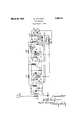
fully-sought by l,means oithe arrangement disclosedzhereinafter. .I I -f This invention resides substantiallyiin-:the combination, arrangement', location and circuitarlvconnections` ofthe yvarious elements as `Willtbe;completely vdescribed below. v The single :ligure :in ithe 'drawing ,isy a diagrammatic illustrationwof the relative .are rangement ,of-the parts ftoigprovide -:my invention. y t
Since the advent of radio frequency ampli fiers employing ithe "well :known three gelectrode 4*audionfit `hasbeen'fthe-laim ,of those skilled inkthe art `to provideay simple tandf ef-V cient means :for preventing fintercircuit .reaction which 'isk productive ofdisturbing .oscillations. In practical operation a multi-` stage ptuned -radio lfrequen cyf amplifier :isy sub ject fto .the iproduction" of yundesirable voscillations'because ofthe/capacity coupling between the rinput :and joutput :circuitsj of each stageV :through the vinherent 1 'capacity ibetweenzthej opiate. andigrid' :ofth'e audion tubes generally employedin su'chfcircuits. :Lhave These -and man 'A other obj ect-s are success-ff devised. la relatively simple ,circuit :Eor
vontngor supprossngthe proluoton ofimr. desirablecurrents in tthe inputzcircuitof each Stage of the radio frequency amplifier. by voor son .ofthe reactionoftbe outputcurrentgupon Referring to the drawing,l the antenna groundsystem is shown oomprisingtheeverhoadnotwork l, tholplmory ofotransformor 2, andthe groundgat 3. The ls*eco/ndary-o-the tothegroundlead andltolthefilament .8 ogtlie first audionf -A variable condenser y.5 isV shunted across the inductanc x4 ifOI ,the lpurpcw se oftuning .the .grid-filamentcircuitof the first u audion :to .the 'frequency of the `iinconning Water-A high resistance sfoonnootodfbol 'loA tween Vthe vgid and .lomont .and provdooiia leakagopoth therebetween Lhowe 'found thata leak `of three megohms issuitable fior thisggpurpose. jflhe plate;` Q/fris connected through tho primary of :a .iredozffroquenoy :transformer l0 .whiehhas vone terminal connected vtoxtheV positive 'side of the "B battery source.-297 the secondary l1 .being shuntedby the @condenser y l2 .and comprising gthe tuned input circuit of the -second iaudion. -One -terf minal ofthisftunedinput circuit isv connected to ,the grid 14 ,and its other terminal is econ-f. nected to vtheilamen't 15. A high resistance grid yleak 13 is kconnected lbetween the ygrid and filament andmay` have a value vof 1the order )of two megohrns. Theplate L6 in nthe second audionfs connected through the `prmary 1'7 'of Va radio Lfrequency `trarisjioltmer Vwhich has its other terminal connectedto the tector tubo ondono termino-'1 ofthe llairlorit 24. A grid condenser y21- and'ygrid leakf22 to transformerfs ShoWnatA-:nd has .onolterm-f naliconnected to the. grid .Tof thev first audion; and Iits other lterminal connected bothy 'we y ofthe usual construction. is 4shown in Vthe grid lead. A high variable '.,resistance 20 a resistance 3l of the order of five megohms,
denser of a value of .O02l micro-farads isv shunted across the sound reproducing device 27j. HThe terminals of lall the cathodes or filaments are connectedV in parallel through of supply 33. The grids of the first and second audions are connected together through and the grid of the second audion or radio frequency amplifier is connected to the grid ofthe detector tube through a resistance 324 It is at once apparent to thoseskilled in the i art that many changes in the details of arrangement of the parts` will readily occur without departing from the scope of this invention. For example, while I have disclosed the invention as applied to a 2-stage radio frequency amplier-and a detector it is, of course, true that the principles of the invention may be applied to amplifiers of anynumber of stages. kWhile I have shown no audio-A frequency stages connected to the radio-frequency amplifiers and detector it is clearly evident that instead of connecting a sound reproducing device in the output circuit of the detector tube that the output terminals could be connected to the input of a multistage audio-frequency amplifier. It will be further evident that the various values of resistance and capacity which I have disclosed as desirable can be varied to suit particular conditions without departing from the spirit and scope of this invention. I also contemplate within the scope of `this disclosure to include a connection between the grid of the last radio frequency amplifier and the plate of the detector rather than the grid of the detector if this is found desirable since Iliave discovered that fairly satisfactory operation is secured thereby.
I do not, therefore, desire to be particularly restricted to the disclosure in the drawing and specification which have been given for the purposes of illustration, but rather to the ieldof my invention as I define it in the appended claims.
g cluding resistances only. the variable resistance 34 to a suitable sourceV What I seek to secure by United States Letters Patent is:
1. In a radio receiving system the combination with a plurality of three electrode audions each including a grid, a plate and filament, an input circuit for each audion including grid and filament and an output circuit for each audion including plate and lament, of a series connection between each grid iii- 2'. In a radio signalling system the com- .bination with a plurality of three electrode audions each having a grid, plate and lament` and-.their associated circuits arranged to provide a cascade yamplifier of aconnection between each set of electrically adjacent grids including a high resistance only whereby all the grids are in series. Y
3. In a radio signalling system the combination with a plurality of three electrode audions each having a grid, plate and filament and their associated circuits arranged to provide a cascade connected multi-stage amplifier and a detector, of a resistance connection between each electrically adjacent grid and a Vresistance connected between the grid of the last amplifier and the grid of the detector tube all of said gridsbeing electrically in series. Y
4. In a multi-stage Vaudion receiving circuit comprising a plurality of radio frequency amplifiers and a detector of a resistance connection between the grid and filament of each `audion and a resistance connection between the grids of all the amplifiers and between the grid of the last radio'frequency amplifier and the gridof the detector.
5. In a radio circuit the combination with an audion amplier stage and an audion detector, said audions having three electrodes, and circuits associating said audions into an operative circuit of a series connection including resistances onlyfbetween the grids of said audions. Y
6. In a radio circuit the combination with an audion amplifier stage and an audion detector, said audions having three electrodes, and circuits associating said audions into an operative circuit of an impedance connection between the grid of the amplifier audion and the grid of the detector audion, and" a variable resistance connected between the grid and filament of said detector. f
7. In a radio circuit the combination with an audion amplifier stage and an audion detector, said audions having three electrodes, and circuits associating said audions into an operative circuit of a connection including a resistance between the grids of said audions, and a variable resistance connected between the grid and filament ofsaid' detector.
8. In a radio receiving circuitthe combination with a plurality of audions each having a plate, grid and filament, said audions being connected to form a multi-stage amplifier lil() nd a detector of an impedance connection between the rids of the amplifiers and the grid of the eteotor, and an adjustable resistance connected between the grid and filament of the detector audion.
In testimony Whereoflv have hereunto set my hand on this 28th day of lebruai'y,v A. D.
" WOLFF 'KAUFMAN
Priority Applications (1)
| Application Number | Priority Date | Filing Date | Title |
|---|---|---|---|
| US172999A US1850110A (en) | 1927-03-05 | 1927-03-05 | Radiocircuit |
Applications Claiming Priority (1)
| Application Number | Priority Date | Filing Date | Title |
|---|---|---|---|
| US172999A US1850110A (en) | 1927-03-05 | 1927-03-05 | Radiocircuit |
Publications (1)
| Publication Number | Publication Date |
|---|---|
| US1850110A true US1850110A (en) | 1932-03-22 |
Family
ID=22630078
Family Applications (1)
| Application Number | Title | Priority Date | Filing Date |
|---|---|---|---|
| US172999A Expired - Lifetime US1850110A (en) | 1927-03-05 | 1927-03-05 | Radiocircuit |
Country Status (1)
| Country | Link |
|---|---|
| US (1) | US1850110A (en) |
-
1927
- 1927-03-05 US US172999A patent/US1850110A/en not_active Expired - Lifetime
Similar Documents
| Publication | Publication Date | Title |
|---|---|---|
| US2293414A (en) | High frequency amplifier circuit | |
| US2324279A (en) | Amplifier | |
| US1850110A (en) | Radiocircuit | |
| US2243141A (en) | Radio receiver circuits | |
| US2018982A (en) | Delayed automatic volume control circuit | |
| US2069809A (en) | Automatic volume control circuit | |
| US2455711A (en) | Bidirectional high gain amplifier | |
| US1930339A (en) | Amplifier | |
| US2310455A (en) | Ultra short wave amplifier circuit | |
| US2172160A (en) | Delayed automatic volume control | |
| US2229674A (en) | Rectifying and amplifying circuits | |
| US2533020A (en) | Circuit arrangement for amplifying ultra high frequency electrical oscillations | |
| US2137265A (en) | Circuit for suppressing disturbance waves and upper harmonics | |
| US1799169A (en) | Radio circuit | |
| US2794865A (en) | Amplifiers having mismatched interstage networks | |
| US2597629A (en) | Electron discharge amplifier | |
| US1517057A (en) | Vacuum-tube amplifier | |
| US2483315A (en) | Superheterodyne receiver | |
| US1861587A (en) | Audion amplifier circuit | |
| US2508416A (en) | Stabilized high-frequency amplifier | |
| US2062691A (en) | Automatic overload control in radio sets | |
| US2247155A (en) | Selectivity control circuits | |
| US2006803A (en) | Short wave receiver | |
| US2020363A (en) | Automatic volume control arrangement | |
| US1841383A (en) | Thermionic amplifier and circuit arrangement therefor |