US1850108A - Method of and apparatus for feeding sheets - Google Patents
Method of and apparatus for feeding sheets Download PDFInfo
- Publication number
- US1850108A US1850108A US409051A US40905129A US1850108A US 1850108 A US1850108 A US 1850108A US 409051 A US409051 A US 409051A US 40905129 A US40905129 A US 40905129A US 1850108 A US1850108 A US 1850108A
- Authority
- US
- United States
- Prior art keywords
- sheets
- pack
- rollers
- feeding
- relay
- Prior art date
- Legal status (The legal status is an assumption and is not a legal conclusion. Google has not performed a legal analysis and makes no representation as to the accuracy of the status listed.)
- Expired - Lifetime
Links
Images

Classifications
-
- B—PERFORMING OPERATIONS; TRANSPORTING
- B65—CONVEYING; PACKING; STORING; HANDLING THIN OR FILAMENTARY MATERIAL
- B65H—HANDLING THIN OR FILAMENTARY MATERIAL, e.g. SHEETS, WEBS, CABLES
- B65H1/00—Supports or magazines for piles from which articles are to be separated
- B65H1/02—Supports or magazines for piles from which articles are to be separated adapted to support articles on edge
- B65H1/025—Supports or magazines for piles from which articles are to be separated adapted to support articles on edge with controlled positively-acting mechanical devices for advancing the pile to present the articles to the separating device
-
- B—PERFORMING OPERATIONS; TRANSPORTING
- B65—CONVEYING; PACKING; STORING; HANDLING THIN OR FILAMENTARY MATERIAL
- B65H—HANDLING THIN OR FILAMENTARY MATERIAL, e.g. SHEETS, WEBS, CABLES
- B65H3/00—Separating articles from piles
- B65H3/02—Separating articles from piles using friction forces between articles and separator
-
- B—PERFORMING OPERATIONS; TRANSPORTING
- B65—CONVEYING; PACKING; STORING; HANDLING THIN OR FILAMENTARY MATERIAL
- B65H—HANDLING THIN OR FILAMENTARY MATERIAL, e.g. SHEETS, WEBS, CABLES
- B65H5/00—Feeding articles separated from piles; Feeding articles to machines
- B65H5/06—Feeding articles separated from piles; Feeding articles to machines by rollers or balls, e.g. between rollers
- B65H5/062—Feeding articles separated from piles; Feeding articles to machines by rollers or balls, e.g. between rollers between rollers or balls
-
- B—PERFORMING OPERATIONS; TRANSPORTING
- B65—CONVEYING; PACKING; STORING; HANDLING THIN OR FILAMENTARY MATERIAL
- B65H—HANDLING THIN OR FILAMENTARY MATERIAL, e.g. SHEETS, WEBS, CABLES
- B65H2701/00—Handled material; Storage means
- B65H2701/10—Handled articles or webs
- B65H2701/17—Nature of material
- B65H2701/173—Metal
Definitions
- Our invention relates to a method of and apparatus for feeding sheet material, and more particularly to the feeding of metal sheets such as the sheets contained in the piles or packs of steel sheets in connection with tin plate mill operations, etc., but may be employed in connection with various other opcrations.
- One object of our invention is to provide a means and a method whereby a pack may be so arranged as to facilitate the feeding of sheets therefrom.
- Another object of our invention is to provide a method of feeding sheet material whereby-single sheets can be easily and positively separated from the remainder of the nick.
- a further object is to provide a sheet feeding apparatus to advance single sheets and to prevent the advancement of double sheets or one which is not suitably formed.
- Still another object of our invention is to simplify and improve generally the structure and operation of sheet-feeding apparatus.
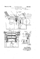
- Figure 1 is a sectional elevational view of a machine for feeding single sheets of a pack
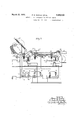
- Fig. 2 is a sectional view taken on the line II.II thereof
- Fig. 3 is a fragmentary end view looking from the left hand side of Fig. 1
- Fig. 4 is' a view, on an enlarged scale, showing a portion of the sheet-guiding mechanism of Fig. 1
- Fig. 5 is an end view thereof
- Fig. 6 is a diagrammatic View showing the manner in which the guiding mechanism of Fig. 4 is controlled
- Fig. 7 is a modification of the apparatus of Fig. 1.
- a base 7 serves as a support for a tilting table or rack 8.
- the rack 8 is supported by links 9, l0 and 11. These links are connected at their upper ends to the table 8 by means of a pin or shaft 12 and at their lower ends they are connected to the base by means of a shaft or pin 13.
- the table is supported entirely by the links 9, 10 and 11, when in upright position as'shown in full lines in Fig. 1.
- a pair of idle rollers 15 which primarily so function to hold a packof sheets 16 against the table, also function in conjunction with a stationary table 17, to prevent the table swinging forward or falling from the position shown in Fig. 1.
- a hand lever 18 which is pivotally connected at 19 to the'link 10 and which has a crank-like extension 20 that is connected 0 through a link 21 to the rear side of the table 8.
- the rib-like extensions 23 of the stationary table 17 are spaced apart such distance as will permit the fingers 26 to pass between'them, when the table 8 is being swung to upright position.
- the extensions 23 are shaped at their upper extremities as indicated at 27, to provide inclined surfaces for guiding the lower edges of the sheets 16 when they are being moved to the full line position of Fig. 1, so that the lower portions of the sheets are deflected on curved lines.
- the sheets at approximately their midortions are broug into position against t e rollers 15 which serve tomaintain them in position against the table.
- Feeding fingers or presser members 28 are mounted upon a shaft 29 that is driven from a shaft 30 through a sprocket chain 31 the shaft 30 being in turn driven from a shaft 32.
- the shaft 32 is provided with a sprocket wheel which may be driven in any suitable manner.
- Each of the fingers 28 has a nose portion 33 that has a sheet-contactin surface preferabl of rubber, leather, or ot er relatively so t material.
- the shank of the nose EOItlOIl has telescopic engagement with the 0d portion of the finger and is yieldably held in expanded relation thereto by means of a compression spring 34, it being understood that the fingers are secured to and rotate with the shaft 29, so that their nose portions will en age the faces of the ex osed sheets and sllde them downwardly o the pack and along the stationary table 17 and between feeding or advancing rolls 35 and 36.
- the roll 35 is carried by the shaft 30 and has frictional contact with the roll 36, either directly or through the medium of a sheet being a vanced by the roll.
- the roll 36 is mounted on a shaft 41 which is springpressed upwardly by springs 37, to allow yieldable vertical movements thereof.
- the feeding fingers 28 of course have a greater radius than the radius of the roll 35 and for this reason, we provide proper gear reduction so that the peripheral speed of the nose portions 33 of the fingers will approximately equal the peripheral rate of travel of the roll 35, and the rolls will therefore advance the sheets at the same rate as that at which the sheets are fed down by the fingers.
- the axis of rotation of the fingers 28 is at such height that the fingers will engage the sheets at points above the rollers 15, where the sheets are held tightly against one another, rather than at points below such rollers 15 where the sheets are spaced apart somewhat as above-explained and the fingers could not engage the sheets with as great pressure.
- the purpose of the apparatus is to feed the sheets from the pack one-by-one. At times, two sheets may be stuck together and therefore be simultaneously moved between the rollers 35 and 36.
- rollers 38 In order to automatically effect this separation or deflection, we mount guide rollers 38 beyond the rollers 35 and 36. These rollers ordinarily direct the sheets to a conveyer 39 which leads to sheetflattening rolls (not shown) or to any other desired destination, the rollers 38 being journaled on a rack 40 which is pivoted at one end to the shaft 41 that carries the roller 36. The outer end of the rack 40 carries a pair of links 42 that depend therefrom and at their lower ends are pivotally connected to links 43.
- the rear ends of the links 43 are connected to a rockshaft 44 that is journaled in the sides of the base 7.
- a weighted arm 45 is secured to the shaft 44. It will be seen that asthe shaft 44 is oscillated, the links 42 will be moved up and down to raise and lower the guide rollers 38.
- the rollers 38 are normally ILnaintained in the position shown in Fig. 1,
- An operating lever 48 for the switch 47 is pivotally mounted at 49 and has its one end bifurcated, with the arms of the bifurcations engaged by the shaft 41, so that as such shaft is moved up and down, the switch lever 48 will be rocked to open and close the switch 47.
- the throw of the switch lever 48 as shown more clearly by the broken lines ar -a, Fig. 4, is such that if two sheets pass between the rolls 35 and 36, the lever will be moved such distance that the switch 47 is opened, thus breaking the control circuit for the solenoid 46 and permitting springs 57 to swing the rack 40 and the rollers 38 carried thereby upwardly such distance that the two sheets will be directed between rollers 50 and 51 to a receiving table or rack 52.
- This breaking of the circuit opens the circuit of an auxiliary relay 53 which, through switch contacts 54, controls the circuit of the solenoid 46 that has connection to a suitable power supply line 60, such circuit being broken by the switches 54 so long as thecoil of the relay 53 is de-energized.
- the solenoid 46 will remain de-energized for a slight period of time after the sheets actually pass between the rolls 3536 to give. such sheets close, thus completing the energizing circuit of a slow-to-energize relay 55, this circuit extending through the now closedcontacts 58 of the relay 53.
- the roll 50 is driven from the shaft 32 by a sprocket chain 58 and suitable sprocket wheels.
- FIG. 7 we show a modified form of the apparatus of Fig. 1. wherein provision has been made for deflecting sheets from the normal path of travel of the separated sheets, in case either the leading edge or the rear edgeof a separated sheet is bent back or bulged.
- apparatus that is actuated by the bent portion of the sheet, such apparatus being in duplicate and each being substantially similar to the deflecting apparatus of Fig. 1.
- the sheets are fed from a pack, one-by-one, by feeding members 2805 and between feeding rolls 35a and 36a.
- a sheet is of abnormal thickness, or the leading edge of the The break the control circuit for a hold-down solenoid 46a, and permitting springs 57a to swing a rack 40a and guide rollers 38a carried thereby upwardly so that such sheets will be directed between rollers 50a and 51a to a receiving table 52a.
- the actuation of the switch 47a does not result in the immediate de-energization of the hold-down solenoid 46a and the swinging up of the deflecting rollers 38a, but the solenoid is maintained ener ized for a short time interval thereafter, or a purpose hereinafter .1 described.
- rollers 38a do not exert a damaging force on a sheet, which would be the case if the rollers were permitted to swing upwardly immediately after the operationofthe switch 47a, since the sheet by its dis-engagement with the rolls 35a and 36a is merely flexed upwardly by the rollers 38.
- a switch 85 is associated with the roll81 and is actuated by the bent. portion ofthesheet in its passage between therolls 80 and 81.
- the actuation of the switch 85 results in the de-energization of a hold-down solenoid 86 through the operation of relays 74 and 75, that operate in the same manneras the relays 53 and 55.
- the solenoid 86 releases the rollers 87 which move upwardly to deflect the sheet between rollers 88 and 89 to a receivin table 90.
- the 'rolls 80 and 81 are space apart such distance from the rollers 88 and 89 that the leading edge of the sheet will be directed between the rollers.
- the rolls 36a, 81 and 84 are spring pressed upwardly to allow yieldable vertical movements thereof.
- the rolls 35a, 80 and 83 and the rollers 50a and 88 are drivenat the same speed in any suitable manner.
- the method of feeding sheets which comprises bending a pack of sheets adjacent to one edge thereof while said edge is in engagement with a supporting surface, and applying a force to the sheets in succession, at points. in advance of the zone of bending and in a direction generally parallel to the plane of the pack.
- Apparatus for feeding sheets comprising a table occupying a generally horiaontal position, a tiltably-mounted table adjacent to one edge of the first-named table, and movable into vertical position to carry a pack of sheets to vertical position, means on the horizontal table for engaging the lower edge of said pack as it is tilted toward vertical position by movement of the second-named table, a stop member positioned to engage the exposed side of the pack when the tilting table reaches approximately a vertical position, and means above the horizontal table movable into position against the exposed side of the pack in a direction generally parallel to said side, 'for feeding sheets therefrom.
- The-method which comprises placing one end of a pack of loosely-assembled sheets against an approximately horizontal supporting surface, bending the pack ad acent to said end at such angle as to permit sheets to he slid from'the pack along said surface, maintaining that part of the pack above the bent portion in approximately an upright position above said surface, the weight of the sheets being imposed on the said surface and applying a feeding force to the sheets in suc-' cession. at the concave side of the pack and in a direction generally parallel to the plane of the pack.
- Apparatus for feeding sheets comprising a table, a rack for receiving a pack of sheets and tiltably-mounted for movement from a plane inclined with respect to the table to -a plane perpendicular thereto, the rack being positioned to deposit the pack endwise upon the table when being tilted to upright position, a stop member for holding the upper portion of the pack against the rack, and a feeder device movable downwardly at the inner side of the pack, for sliding sheets therefrom.
- Apparatus for feeding sheets comprising a table, a pack-holding device movable to bring one edge portion of a pack of sheets into engagement with the table and cause further movement of another ortion of the pack, to effect bendin thereof: and a feeder device operating at he concave side of the pack to slide sheets therefrom.
Landscapes
- Engineering & Computer Science (AREA)
- Mechanical Engineering (AREA)
- Sheets, Magazines, And Separation Thereof (AREA)
Description
March 22, 1932. P. E. HUNTERET AL 1,850,108
I METH OD OF AND APPARATUS FOR FEEDING SHEETS Filed Nov. 22, 1929 s Sheds-Sheet 1 Fig. 1.
| l I I I I I I l l I I l I 1 l March 22, 1932. P. E. HUNTER ET AL METHOD OF AND APPARATUS FOR FEEDING SHEETS Filed Nov. 22, 1929 w 5 Sheets-Sheet INVENTORS ll .ll|||||| Mal -ch- 22, 1932.
P. E. HUNTER ET AL METHOD OF AND APPARATUS FOR FEEDING SHEETS Filed Nov. 22, 1929 2' Sheets-Sheet INVENTORS Patented 'Mar. 22, 1932 PATENT. OFFICE PERCY E. HUNTER AND LOUIS E. ENDSLEY, OF PITTSBURGH, PENNSYEVANIA; SAID ENDSLEY ASSIGNOR TO SAID HUNTER METHOD OF AND APPARATUS FOR FEEDING SHEETS Application filed November 22, 1929. Serial No. 409,051.
Our invention relates to a method of and apparatus for feeding sheet material, and more particularly to the feeding of metal sheets such as the sheets contained in the piles or packs of steel sheets in connection with tin plate mill operations, etc., but may be employed in connection with various other opcrations.
In tin plate mill operations, it is desirable in that the metal sheets of a pack, after having been loosened or separated in any well-known manner, be arranged to be automatically fed, one-by-one to various of the machines used in the making of tin plate.
One object of our invention is to provide a means and a method whereby a pack may be so arranged as to facilitate the feeding of sheets therefrom.
Another object of our invention is to provide a method of feeding sheet material whereby-single sheets can be easily and positively separated from the remainder of the nick.
I A further object is to provide a sheet feeding apparatus to advance single sheets and to prevent the advancement of double sheets or one which is not suitably formed.
Still another object of our invention is to simplify and improve generally the structure and operation of sheet-feeding apparatus.
One form of apparatus by which our invention may be practised is illustrated in the accompanying drawings wherein Figure 1 is a sectional elevational view of a machine for feeding single sheets of a pack; Fig. 2 is a sectional view taken on the line II.II thereof; Fig. 3 is a fragmentary end view looking from the left hand side of Fig. 1; Fig. 4 is' a view, on an enlarged scale, showing a portion of the sheet-guiding mechanism of Fig. 1 Fig. 5 is an end view thereof; Fig. 6 is a diagrammatic View showing the manner in which the guiding mechanism of Fig. 4 is controlled, and Fig. 7 is a modification of the apparatus of Fig. 1.
lVhilethe apparatusis hereinafterdescribed as employed in, connection with the handling and feeding of metal sheets, it will be understood that it is capable of use in connection with various other materials.
A base 7 serves as a support for a tilting table or rack 8. The rack 8 is supported by links 9, l0 and 11. These links are connected at their upper ends to the table 8 by means of a pin or shaft 12 and at their lower ends they are connected to the base by means of a shaft or pin 13. The table is supported entirely by the links 9, 10 and 11, when in upright position as'shown in full lines in Fig. 1.
A pair of idle rollers 15 which primarily so function to hold a packof sheets 16 against the table, also function in conjunction with a stationary table 17, to prevent the table swinging forward or falling from the position shown in Fig. 1. I
In order to swing the table 8 to the dotted line position for receiving a pack of sheets, we provide a hand lever 18 which is pivotally connected at 19 to the'link 10 and which has a crank-like extension 20 that is connected 0 through a link 21 to the rear side of the table 8.
With the parts in full line position as shown in Fig. 1, forward movement of the lever 18 will result in the link 21 being shifted to the right, thus swinging the table on its pivot 12 to the dotted line position. When the table reaches the position shown in dotted lines, stop members 22 will engage against the undersides of rib-like portions or extensions 23 of the stationary table 17 to limit further tilting movement of the table 8. With the parts in dotted line position, the links will rest against a bar or web 24 that projects upwardly from the base and serves as a stop.
When the table 8 is in the position shown in Fig. 1 there is necessarily considerable pressure against the front or upper side thereof tending to return theparts to dotted y line position. The connection at 20a between the handle 18 and the link 20 is below or over dead center with respect to the pivot point 19, the handle bearing against a stop member 25 on the linklO. The parts are thuslocked in the. position shown in Fig. 1, until the handle 18 is elevated toward dotted line position.
With the table in the dotted line position of Fig. 1, a pack of sheets 16 is placed thereon, the lower edges of the sheets bearing against upwardly projecting fingers 26 at the lower edge of the table.
The rib-like extensions 23 of the stationary table 17 are spaced apart such distance as will permit the fingers 26 to pass between'them, when the table 8 is being swung to upright position. The extensions 23 are shaped at their upper extremities as indicated at 27, to provide inclined surfaces for guiding the lower edges of the sheets 16 when they are being moved to the full line position of Fig. 1, so that the lower portions of the sheets are deflected on curved lines. The sheets at approximately their midortions are broug into position against t e rollers 15 which serve tomaintain them in position against the table. It will be seen that the flexing of the lower portions of the sheets will have the effect of spacin them somewhat so that when sheets are to e slid therefrom one-b one as hereinafter explained, there will e no vacuum or suction effect tending to resist sliding of the sheets, but rather an air film which will facilitate the sliding thereof oneby-one off the pack.
- Feeding fingers or presser members 28 are mounted upon a shaft 29 that is driven from a shaft 30 through a sprocket chain 31 the shaft 30 being in turn driven from a shaft 32. The shaft 32 is provided with a sprocket wheel which may be driven in any suitable manner. Each of the fingers 28 has a nose portion 33 that has a sheet-contactin surface preferabl of rubber, leather, or ot er relatively so t material. The shank of the nose EOItlOIl has telescopic engagement with the 0d portion of the finger and is yieldably held in expanded relation thereto by means of a compression spring 34, it being understood that the fingers are secured to and rotate with the shaft 29, so that their nose portions will en age the faces of the ex osed sheets and sllde them downwardly o the pack and along the stationary table 17 and between feeding or advancing rolls 35 and 36.
The roll 35 is carried by the shaft 30 and has frictional contact with the roll 36, either directly or through the medium of a sheet being a vanced by the roll. The roll 36 is mounted on a shaft 41 which is springpressed upwardly by springs 37, to allow yieldable vertical movements thereof.
The feeding fingers 28 of course have a greater radius than the radius of the roll 35 and for this reason, we provide proper gear reduction so that the peripheral speed of the nose portions 33 of the fingers will approximately equal the peripheral rate of travel of the roll 35, and the rolls will therefore advance the sheets at the same rate as that at which the sheets are fed down by the fingers. The axis of rotation of the fingers 28 is at such height that the fingers will engage the sheets at points above the rollers 15, where the sheets are held tightly against one another, rather than at points below such rollers 15 where the sheets are spaced apart somewhat as above-explained and the fingers could not engage the sheets with as great pressure.
As heretofore stated, the purpose of the apparatus is to feed the sheets from the pack one-by-one. At times, two sheets may be stuck together and therefore be simultaneously moved between the rollers 35 and 36.
In such case it is desired to deflect the adher ing sheets from the normal path of travel of the separated sheets. In order to automatically effect this separation or deflection, we mount guide rollers 38 beyond the rollers 35 and 36. These rollers ordinarily direct the sheets to a conveyer 39 which leads to sheetflattening rolls (not shown) or to any other desired destination, the rollers 38 being journaled on a rack 40 which is pivoted at one end to the shaft 41 that carries the roller 36. The outer end of the rack 40 carries a pair of links 42 that depend therefrom and at their lower ends are pivotally connected to links 43.
The rear ends of the links 43 are connected to a rockshaft 44 that is journaled in the sides of the base 7. A weighted arm 45 is secured to the shaft 44. It will be seen that asthe shaft 44 is oscillated, the links 42 will be moved up and down to raise and lower the guide rollers 38. The rollers 38 are normally ILnaintained in the position shown in Fig. 1,
3 controlled by a switch 47. An operating lever 48 for the switch 47 is pivotally mounted at 49 and has its one end bifurcated, with the arms of the bifurcations engaged by the shaft 41, so that as such shaft is moved up and down, the switch lever 48 will be rocked to open and close the switch 47. The throw of the switch lever 48 as shown more clearly by the broken lines ar -a, Fig. 4, is such that if two sheets pass between the rolls 35 and 36, the lever will be moved such distance that the switch 47 is opened, thus breaking the control circuit for the solenoid 46 and permitting springs 57 to swing the rack 40 and the rollers 38 carried thereby upwardly such distance that the two sheets will be directed between rollers 50 and 51 to a receiving table or rack 52.
This breaking of the circuit opens the circuit of an auxiliary relay 53 which, through switch contacts 54, controls the circuit of the solenoid 46 that has connection to a suitable power supply line 60, such circuit being broken by the switches 54 so long as thecoil of the relay 53 is de-energized. The solenoid 46 will remain de-energized for a slight period of time after the sheets actually pass between the rolls 3536 to give. such sheets close, thus completing the energizing circuit of a slow-to-energize relay 55, this circuit extending through the now closedcontacts 58 of the relay 53.
After a short interval of time this relay,
55, through its associated switch 56 completes a circuit through the coil of the relay 53 which results in closing of the switch contacts 54 to cause the energization of the solenoid 46 from the power line60, thus causing the solenoid 46 to return the rack 40 to its lower position, as shown in Fig. 1, against the tension of the springs 57. The energization of the relay 53 also completes a holding circuit for itself at the contacts 59, and opens the circuit of the relay 55 at the contacts 58 and this relay restores to normal. springs 57 are depended upon to swing the rack 40 and therolls 38 to upper position when the coil 46 is de-energized and the weighted lever 45 serves as a counter-balance for such rack and rolls.
It will therefore be seen that at a predetermined time after two adhering sheets have passed from between the rolls 35 and 36 and are passing through the rolls and 51 to the table 52, the guide rolls 38 will be returned to their lower position to direct succeeding sheets to the conveyer 39.
When a sheet of abnormal thickness passes between the rolls 3536 the above-described operation takes place and delivers such sheet to the table 52. Also, if the leading or forward edge of a sheet is bent back or bulged to such an extent that it might cause damage to the sheet-flattening rolls, the solenoid 46 will be de-energized as above described and such sheet will be directed through the rollers 5051 to the table 52. The time element of the relay is suflicient to permit the guide rollers 38 to remain in elevated position un-. til the deformed sheet enters the rollers 50 51. In this manner, only the desired sheets are permitted to advance one-by-one to the conveyer 39.
The roll 50 is driven from the shaft 32 by a sprocket chain 58 and suitable sprocket wheels.
Referring to Fig. 7, we show a modified form of the apparatus of Fig. 1. wherein provision has been made for deflecting sheets from the normal path of travel of the separated sheets, in case either the leading edge or the rear edgeof a separated sheet is bent back or bulged. In order to automatically effect this deflection of damaged sheets, we provide apparatus that is actuated by the bent portion of the sheet, such apparatus being in duplicate and each being substantially similar to the deflecting apparatus of Fig. 1.
The sheets are fed from a pack, one-by-one, by feeding members 2805 and between feeding rolls 35a and 36a. In case a sheet is of abnormal thickness, or the leading edge of the The break the control circuit for a hold-down solenoid 46a, and permitting springs 57a to swing a rack 40a and guide rollers 38a carried thereby upwardly so that such sheets will be directed between rollers 50a and 51a to a receiving table 52a.
The actuation of the switch 47a does not result in the immediate de-energization of the hold-down solenoid 46a and the swinging up of the deflecting rollers 38a, but the solenoid is maintained ener ized for a short time interval thereafter, or a purpose hereinafter .1 described.
The actuation of the'switch- 47 a results in the de-energization of a relay or switch 70, and at contacts 76 of this relay open the circuit of a slow-to-deenergize relay 71. After a short interval of time, relay 71 de-energizes and at contacts 7 7 opens the circuit of a relay 72 which de-energizes.
At contacts 78 of the relay 71 an energizing circuit is completed for the relay which extends through the switch 47a and this relay energizes to complete a locking circuit for itself at contacts 79 and to complete the energizing circuit for the relay 71., Relay 71' energizes and at contacts 78 opens the original energizing circuit for the relay 70, and at contacts 77 completes a point in the battery circuit for the relays 72 and 73. The operation of the relay 72 which is now de-energized, and the slow-to-energize relay 73 is the same as the operation of the relays 53 and 55, as heretofore described.
Thus, sheets of abnormal thickness or sheets having their forward edge bent back ciated with'the roll 36a, but due to the retard- I ed action of'the control circuit, the solenoid 46a remains energized for a short time interval, permitting the sheet to completely pass from between the rolls 35a and 36a before the rollers 38a swing up in their deflecting movement.
The rollers 38a do not exert a damaging force on a sheet, which would be the case if the rollers were permitted to swing upwardly immediately after the operationofthe switch 47a, since the sheet by its dis-engagement with the rolls 35a and 36a is merely flexed upwardly by the rollers 38. r
A switch 85 is associated with the roll81 and is actuated by the bent. portion ofthesheet in its passage between therolls 80 and 81. The actuation of the switch 85 results in the de-energization of a hold-down solenoid 86 through the operation of relays 74 and 75, that operate in the same manneras the relays 53 and 55. The solenoid 86 releases the rollers 87 which move upwardly to deflect the sheet between rollers 88 and 89 to a receivin table 90. The 'rolls 80 and 81 are space apart such distance from the rollers 88 and 89 that the leading edge of the sheet will be directed between the rollers.
The rolls 36a, 81 and 84 are spring pressed upwardly to allow yieldable vertical movements thereof. The rolls 35a, 80 and 83 and the rollers 50a and 88 are drivenat the same speed in any suitable manner.
We claim as our invention 1. The method of feeding sheets which comprises bending a pack of sheets adjacent to one edge thereof while said edge is in engagement with a supporting surface, and applying a force to the sheets in succession, at points. in advance of the zone of bending and in a direction generally parallel to the plane of the pack.
2. Apparatus for feeding sheets comprising a table occupying a generally horiaontal position, a tiltably-mounted table adjacent to one edge of the first-named table, and movable into vertical position to carry a pack of sheets to vertical position, means on the horizontal table for engaging the lower edge of said pack as it is tilted toward vertical position by movement of the second-named table, a stop member positioned to engage the exposed side of the pack when the tilting table reaches approximately a vertical position, and means above the horizontal table movable into position against the exposed side of the pack in a direction generally parallel to said side, 'for feeding sheets therefrom. V
3. The-method which comprises placing one end of a pack of loosely-assembled sheets against an approximately horizontal supporting surface, bending the pack ad acent to said end at such angle as to permit sheets to he slid from'the pack along said surface, maintaining that part of the pack above the bent portion in approximately an upright position above said surface, the weight of the sheets being imposed on the said surface and applying a feeding force to the sheets in suc-' cession. at the concave side of the pack and in a direction generally parallel to the plane of the pack.
4. The method which comprises placing one end of a pack of loosely-assembled sheets against a supporting surface, bending the pack adjacent to said end at such angle as to permit sheets to be slid from the pack along said surface, with approximately all of the sheets in engagement with the said surface,
supporting the unbent portion of the pack in a plane substantially perpendicular to the plane of the said surface, and applying a feedlngforce to the sheets in succession, at the concave side of the pack, at points in advance of the bend, and in a direction generally parallel to the plane of the pack.
5. The method which comprises placin one end of a pack of loosely-assembled s eets against a supporting surface, bending the pack adjacent to said end at such angle as to permit sheets to he slid from the pack along said surface, with approximately all of the sheets in engagement with the said surface,
supporting the unbent portion of the pack,
in a plane substantially perpendicular to the plane of the said surface, and applying a feeding force to the sheets in succession, at the concave side of the pack and in a direction generally parallel to the plane of the pack, the feeding force being in the nature of a wiping action initiated at a point in advance of the. bend.
6. Apparatus for feeding sheets, comprising a table, a rack for receiving a pack of sheets and tiltably-mounted for movement from a plane inclined with respect to the table to -a plane perpendicular thereto, the rack being positioned to deposit the pack endwise upon the table when being tilted to upright position, a stop member for holding the upper portion of the pack against the rack, and a feeder device movable downwardly at the inner side of the pack, for sliding sheets therefrom.
7. Apparatus for feeding sheets,comprising a table, a pack-holding device movable to bring one edge portion of a pack of sheets into engagement with the table and cause further movement of another ortion of the pack, to effect bendin thereof: and a feeder device operating at he concave side of the pack to slide sheets therefrom.
Intestimony whereof we, the said PERCY E. HUNTER and Lows E. ENDsLEY have hereunto set our hands.
- PERCY E. HUNTER.
LOUIS E. ENDSLEY.-
Priority Applications (2)
| Application Number | Priority Date | Filing Date | Title |
|---|---|---|---|
| US409051A US1850108A (en) | 1929-11-22 | 1929-11-22 | Method of and apparatus for feeding sheets |
| US584652A US1966504A (en) | 1929-11-22 | 1932-01-04 | Apparatus for sorting sheets |
Applications Claiming Priority (1)
| Application Number | Priority Date | Filing Date | Title |
|---|---|---|---|
| US409051A US1850108A (en) | 1929-11-22 | 1929-11-22 | Method of and apparatus for feeding sheets |
Publications (1)
| Publication Number | Publication Date |
|---|---|
| US1850108A true US1850108A (en) | 1932-03-22 |
Family
ID=23618854
Family Applications (1)
| Application Number | Title | Priority Date | Filing Date |
|---|---|---|---|
| US409051A Expired - Lifetime US1850108A (en) | 1929-11-22 | 1929-11-22 | Method of and apparatus for feeding sheets |
Country Status (1)
| Country | Link |
|---|---|
| US (1) | US1850108A (en) |
Cited By (11)
| Publication number | Priority date | Publication date | Assignee | Title |
|---|---|---|---|---|
| US2793032A (en) * | 1953-12-14 | 1957-05-21 | Harold W Van Dusen | Sheet collating machine |
| US3137497A (en) * | 1961-01-23 | 1964-06-16 | Paul F Good | Sheet loosening method and apparatus |
| US3599968A (en) * | 1969-12-24 | 1971-08-17 | Fmc Corp | Veneer-sheet-feeding apparatus |
| US3614093A (en) * | 1968-12-07 | 1971-10-19 | Mabeg Maschinenbau Gmbh Nachl | Supervisory device for a sheet feeder |
| US4491312A (en) * | 1982-05-14 | 1985-01-01 | Burroughs Corporation | Automatic feeder-loader for cut sheet paper |
| US5137174A (en) * | 1991-01-30 | 1992-08-11 | Xerox Corporation | Pivoting paper tray |
| US5154408A (en) * | 1990-12-28 | 1992-10-13 | Pitney Bowes Inc. | High capacity sheet feeder with adjustable deck |
| EP1256448A3 (en) * | 2001-05-07 | 2004-03-31 | LTG Mailänder GmbH | Sheet guide for a sheet processing machine and method for guiding a sheet |
| US20040135866A1 (en) * | 2002-12-23 | 2004-07-15 | Samsung Electronics Co., Ltd. | Paper feeding apparatus of printer |
| US20050195259A1 (en) * | 2004-03-05 | 2005-09-08 | Brother Kogyo Kabushiki Kaisha | Discharge roller, conveyance apparatus, and recording apparatus |
| CN108423455A (en) * | 2017-09-20 | 2018-08-21 | 汝州市中鼎科技有限公司 | A kind of meeting papery data material sending machine |
-
1929
- 1929-11-22 US US409051A patent/US1850108A/en not_active Expired - Lifetime
Cited By (12)
| Publication number | Priority date | Publication date | Assignee | Title |
|---|---|---|---|---|
| US2793032A (en) * | 1953-12-14 | 1957-05-21 | Harold W Van Dusen | Sheet collating machine |
| US3137497A (en) * | 1961-01-23 | 1964-06-16 | Paul F Good | Sheet loosening method and apparatus |
| US3614093A (en) * | 1968-12-07 | 1971-10-19 | Mabeg Maschinenbau Gmbh Nachl | Supervisory device for a sheet feeder |
| US3599968A (en) * | 1969-12-24 | 1971-08-17 | Fmc Corp | Veneer-sheet-feeding apparatus |
| US4491312A (en) * | 1982-05-14 | 1985-01-01 | Burroughs Corporation | Automatic feeder-loader for cut sheet paper |
| US5154408A (en) * | 1990-12-28 | 1992-10-13 | Pitney Bowes Inc. | High capacity sheet feeder with adjustable deck |
| US5137174A (en) * | 1991-01-30 | 1992-08-11 | Xerox Corporation | Pivoting paper tray |
| EP1256448A3 (en) * | 2001-05-07 | 2004-03-31 | LTG Mailänder GmbH | Sheet guide for a sheet processing machine and method for guiding a sheet |
| US20040135866A1 (en) * | 2002-12-23 | 2004-07-15 | Samsung Electronics Co., Ltd. | Paper feeding apparatus of printer |
| US7481424B2 (en) * | 2002-12-23 | 2009-01-27 | Samsung Electronics Co., Ltd. | Paper feeding apparatus of printer |
| US20050195259A1 (en) * | 2004-03-05 | 2005-09-08 | Brother Kogyo Kabushiki Kaisha | Discharge roller, conveyance apparatus, and recording apparatus |
| CN108423455A (en) * | 2017-09-20 | 2018-08-21 | 汝州市中鼎科技有限公司 | A kind of meeting papery data material sending machine |
Similar Documents
| Publication | Publication Date | Title |
|---|---|---|
| US1850108A (en) | Method of and apparatus for feeding sheets | |
| US2177460A (en) | Sheet feeding and overlapping mechanism | |
| US3486749A (en) | Card feeding mechanism | |
| US2733064A (en) | martin | |
| US3034784A (en) | Feeding equipment | |
| US3570842A (en) | Delivery apparatus for sheets or plates | |
| US2298368A (en) | Calipering mechanism | |
| US2208978A (en) | Sheet delivery mechanism | |
| US2545798A (en) | Sheet folding machine | |
| US2794534A (en) | Carton spacing device for conveyers | |
| US3419261A (en) | Folder for optional quarter fold or french fold | |
| US2145520A (en) | Gathering machine | |
| US2890884A (en) | Multiple sheet electing mechanism | |
| US3100110A (en) | Apparatus for removing blanks or sheets from the top of a supply stack | |
| US3089693A (en) | Signature handling apparatus | |
| US2950914A (en) | Sheet feeding apparatus | |
| US1292641A (en) | Mechanism for feeding sheets, pamphlets, or analogous articles. | |
| US824755A (en) | Front register for sheet-folding and other machines. | |
| US2886314A (en) | Sheet stack aligning mechanism | |
| US3029979A (en) | Machines for dispensing adhesive labels and the like | |
| US1225740A (en) | Buckling device. | |
| US3019012A (en) | Collator | |
| GB1312680A (en) | Vacuum operated sheet feeding mechanism for newspaper inserter | |
| US2154022A (en) | Device for automatically stopping sheet conveyers for printing or like machines | |
| US2289501A (en) | Friction stream feeder |