US1850103A - Combined spot and flood light - Google Patents
Combined spot and flood light Download PDFInfo
- Publication number
- US1850103A US1850103A US344701A US34470129A US1850103A US 1850103 A US1850103 A US 1850103A US 344701 A US344701 A US 344701A US 34470129 A US34470129 A US 34470129A US 1850103 A US1850103 A US 1850103A
- Authority
- US
- United States
- Prior art keywords
- lens
- spread
- light
- source
- spot
- Prior art date
- Legal status (The legal status is an assumption and is not a legal conclusion. Google has not performed a legal analysis and makes no representation as to the accuracy of the status listed.)
- Expired - Lifetime
Links
- 239000006185 dispersion Substances 0.000 description 2
- 101100379080 Emericella variicolor andB gene Proteins 0.000 description 1
- 230000003247 decreasing effect Effects 0.000 description 1
Images

Classifications
-
- F—MECHANICAL ENGINEERING; LIGHTING; HEATING; WEAPONS; BLASTING
- F21—LIGHTING
- F21S—NON-PORTABLE LIGHTING DEVICES; SYSTEMS THEREOF; VEHICLE LIGHTING DEVICES SPECIALLY ADAPTED FOR VEHICLE EXTERIORS
- F21S10/00—Lighting devices or systems producing a varying lighting effect
-
- F—MECHANICAL ENGINEERING; LIGHTING; HEATING; WEAPONS; BLASTING
- F21—LIGHTING
- F21V—FUNCTIONAL FEATURES OR DETAILS OF LIGHTING DEVICES OR SYSTEMS THEREOF; STRUCTURAL COMBINATIONS OF LIGHTING DEVICES WITH OTHER ARTICLES, NOT OTHERWISE PROVIDED FOR
- F21V14/00—Controlling the distribution of the light emitted by adjustment of elements
-
- F—MECHANICAL ENGINEERING; LIGHTING; HEATING; WEAPONS; BLASTING
- F21—LIGHTING
- F21W—INDEXING SCHEME ASSOCIATED WITH SUBCLASSES F21K, F21L, F21S and F21V, RELATING TO USES OR APPLICATIONS OF LIGHTING DEVICES OR SYSTEMS
- F21W2131/00—Use or application of lighting devices or systems not provided for in codes F21W2102/00-F21W2121/00
- F21W2131/40—Lighting for industrial, commercial, recreational or military use
- F21W2131/406—Lighting for industrial, commercial, recreational or military use for theatres, stages or film studios
Definitions
- This invention relates to projector or spotlights particularly adapted for illuminating the stage in theaters, public halls andthe like.
- it is frequently desirable to vary the spread of the beam so as to change the light from a spot-light into a flood-light with a variable angle of spread/T0 such end,it is usual to provide means for relatively'adjus'ting the source of light andfthe obj ective' lens.
- thisjinvention relates to means for providing an additional range of .variation without causing transitory flashing or dispersion. of "the beam which is objectionable. Tothis.
- I i provide an auxiliary lens which I introduce preferably between the objeotive'and the source of light.xSaidlensis'preferably introduced in such a manner as'to causefa' change in the spread .ofthe beam to take place smoothly and withia minimum amount of flashing as the lenscomes'in.
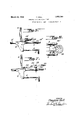
- Fig. 11 s a side elevation showingthelamp housing, obj ective'lens, and myf'improved re- 7 parts separated movable spread lens between the same.
- Fig. 2 is a plan view of the objective and auxiliary lense's, the parts being positioned differently than in Fig. 1. p 1 v, 1
- Fig; 3 is a side view of the. same with the.
- I I Fig. t' is a side elevation showing a modified; form of auxiliary lens.
- FIG. 5 is aside elevation of stillanother form of auxiliary lens mounting.
- Fig. 6 is a fication.
- Fig. 7 is aside elevation of theformf of lenses'shown inFig. 6.
- the housing for the source of plan view of still another modianysuitable form, but is pr'ef'erablya high intensity are light.
- the housing is shown as'm'ounted on suitable supporting rodsQ, the light emerging through the usual lens system 3, Adjustabl'y mounted on said support. 2 is" 1929. serial n5. 344,791.
- the objective lens 4 which isshown connected to the adjusting'handlefi by rod 6.
- a suitable stop 7 isshown' for limiting the outward movementof thelens, inwhich position the.
- the lenses are pivoted on a hollow frame work 40 which in turn is adjustablymount ed on the guide rods 52.. .
- the pivot rods 11' and 12 are shown as providedatthe lower ends with cam rollers 16. Said rollers-normallypro ject in the path of plate 'f 10s0 that as'said ally the edge 10 pushes past therollers and 'the'rollers engage the side edges of the plate as shown in Fig. 2.
- This construction -causes the lenses to close quickly as the plate reaches the rollers and to remain closed during the subsequent adjustment of ithexlens 4 for. further variations of the beam spread. Since. the cam plate 10 has straight side edges the lens 4 can be focused withoutdrawing the lens 8- out of position. Vvhenyhoweverflhe lens'4 is againreturned to the position ',in
- auxiliary lens 18 is shown as mounted on an arm 19 secured to the base 9 of lens a so that the distance betweenthe two lenses remains fixed. In this case the auxiliary lens is thrown into and out of position by rotating the shaft 20.
- Said shaft is shown as provided with a pinion 21 in connection with rack teeth 22 on a link 23.
- Said link is shown as connected to a lever 23 pivoted at 24: and connected through link25 to an car 26 on said lens 18. Itwill readily .be seen that as the shaft 20 is rotated the lens 18 may be revolved counter-clockwise in Fig. a to a pos1tion without the beam or thrown quickly into position in the beam, as desired.
- a stop pin 34 may be provided. to limit the throw of the links and lens.
- auxiliary lens is operated by a cam plate 30, secured to the main lens i.
- the auxiliary lens 28 is made in one piece and is pivoted at 29 on bracket 30 adjustably secured to support 2. Said lens is normally maintained in the position shown in Figs. 6
- Fig. 5 still another form is shown.
- the lens is pivotally secured to the base 9 oflens l: as by being pivoted on an arm 34. extending therefrom.
- Said lens is normally maintained in the position shown in Fig. 5 by a coil spring, not shown, and is revolved to and maintained in an upright position when the downwardly projecting car 32 thereon strikes the adjustable sto-p34 on the rod 2.v
- auxiliary lens in all forms of the invention is entirely out of beam when the beam is in the form of a spotlight or moderately spread. As, however, the spread of the beam is in;
- the auxiliary lens is automatically brought into the beam at the proper point and without causing flashing of the beam, the auxiliary lens being maintained in this position during subsequent focu'singvand adjustments of the beam as long as awide angle spread is desired.
- the auxiliary lens is automatically thrown out ofthe beam as explained.
- a spot-light projector the combination with the source of light and objective lens, of means for relatively adjusting said source and lens to vary the spread of the beam, an auxiliary lens normally without the beam, and means brought into action when said adjustment has reached a predetermined point for moving it into the beam to increase the spread V V I 3.
- the combination with the source of light and objective .Iens,lof means for relatively adjusting said source and lens to vary the spread of the beam, a split auxiliary-lens, means for pivoting each half thereof on a pivot lying without and to either side of the beam andextending substantially parallel to the plane of the lens, and means for opening and closing said lens to vary the beam spread.
- a spot-light projector the combination with the source of light and objective lens, of means for relatively adjusting said source and lens to vary the spread of. the beam, a split auxiliary lens, means for pivotingeach half thereof to either side of the beam, and means brought into action when said adjustment has reached apredetermined point for opening and closing said lens to lens in the beam during subsequent further adjustment of the beam spread.
- the combination with the source 'of' light and objective lens of means for relatively adjusting said source and lens to vary the spread of the beani, an auxiliary lens normally without-the beam, and a cam jCiLIIlBd by said objective lensforrotat ng said aux liary lens to and maintaining it in a position within the beam.
- a spot-light projector the combination, with the source of light and objective lens, of means for .relatively'adjusting said source and lens to vary the spread of the beam, a split auxiliary lens, means for pivoting each half thereof to either side of the beam, a cam plate having straight sides carried by said objective lens, and arms on said 10 split lens extending in the path of" saidzplate whereby both halves of said split lens are 7 simultaneously closed and maintained closed as the objective lens moves toward said split lens, 7
Description
March 22, 1932." HALL 1,850,103
COMBINED SPOT AND FLOOD LIGHT Filed March 6, 1929 2 Sheets-Sheet 1 i|lllllfllllllllllllllllllll INVENTOR Teaaore I/QZZ March 22, 1932. T. HALL 1,850,103
COMBINED SPOT AND FLOOD LIGHT Filed March 6; 19,29 2 Sheets-Sheet 2 INVENTOR Patented Mar. 22, 19321.1"
; UNITED: STATES THEODOREHALL, OF NEW YORK, N.*Y.', ASSIGNOR. T &..CONNOLLY, INC OF N i YORK,:N. Y., A. CORPOR-ATIONLOF NEW YORK COMBINED sro'r gm rnoop LIGHT H lA p'plieation filed ma a's;
This inventionrelates to projector or spotlights particularly adapted for illuminating the stage in theaters, public halls andthe like. In such apparatusit is frequently desirable to vary the spread of the beam so as to change the light from a spot-light into a flood-light with a variable angle of spread/T0 such end,it is usual to provide means for relatively'adjus'ting the source of light andfthe obj ective' lens. 'Bysuch means, however, only a limited amount of variation in the spread of the beam can be obtainedand thisjinventionrelates to means for providing an additional range of .variation without causing transitory flashing or dispersion. of "the beam which is objectionable. Tothis. end, I i provide an auxiliary lens which I introduce preferably between the objeotive'and the source of light.xSaidlensis'preferably introduced in such a manner as'to causefa' change in the spread .ofthe beam to take place smoothly and withia minimum amount of flashing as the lenscomes'in.
Referring to the drawings in which several preferred embodiments of the invention are shown,
.Fig. 11s a side elevation showingthelamp housing, obj ective'lens, and myf'improved re- 7 parts separated movable spread lens between the same.
' *Fig. 2 is a plan view of the objective and auxiliary lense's, the parts being positioned differently than in Fig. 1. p 1 v, 1
Fig; 3 is a side view of the. same with the.
j and the auxiliaryflens out of position. I I Fig. t'is a side elevation showing a modified; form of auxiliary lens. I
'Fig. 5 is aside elevation of stillanother form of auxiliary lens mounting.
Fig. 6 is a fication. j I, Fig. 7 is aside elevation of theformf of lenses'shown inFig. 6. I 3 a In Fig. 1 the housing for the source of plan view of still another modianysuitable form, but is pr'ef'erablya high intensity are light. The housing "is shown as'm'ounted on suitable supporting rodsQ, the light emerging through the usual lens system 3, Adjustabl'y mounted on said support. 2 is" 1929. serial n5. 344,791. j
the objective lens 4:, which isshown connected to the adjusting'handlefi by rod 6. A suitable stop 7 isshown' for limiting the outward movementof thelens, inwhich position the.
beam is in ,the'form of a spot-light; To
spread the beam the operator moves the handle 5 to the right in Fig.1. As the lens moves slightly beyondthe. position shown in Fig. 1,
it nears the range of 1 spread possible. with 12 on opposite sides of the beam. As shown,
the lenses are pivoted on a hollow frame work 40 which in turn is adjustablymount ed on the guide rods 52.. .The two'halves 'are normally maintained opened, that is; in the position shown in Figs. 1 and 3,; by'fcoil springs 15., The pivot rods 11' and 12 are shown as providedatthe lower ends with cam rollers 16. Said rollers-normallypro ject in the path of plate 'f 10s0 that as'said ally the edge 10 pushes past therollers and 'the'rollers engage the side edges of the plate as shown in Fig. 2. This construction-causes the lenses to close quickly as the plate reaches the rollers and to remain closed during the subsequent adjustment of ithexlens 4 for. further variations of the beam spread. Since. the cam plate 10 has straight side edges the lens 4 can be focused withoutdrawing the lens 8- out of position. Vvhenyhoweverflhe lens'4 is againreturned to the position ',in
Figs. '1 andB, theftwo halves of the len'sS- are thrownout of the beam quickly by ,the'
, plate ismoved to the right in Fig'sQ 1 and 3 the front edge 10 thereof first engagesithe V rollers and rotatesthein inwardlyuntil fin! coil springs -1 5 zwithoutfcausing flashing off the beamif' v j In the modificationaecording to Fig. 4 the auxiliary lens 18 is shown as mounted on an arm 19 secured to the base 9 of lens a so that the distance betweenthe two lenses remains fixed. In this case the auxiliary lens is thrown into and out of position by rotating the shaft 20. Said shaft is shown as provided with a pinion 21 in connection with rack teeth 22 on a link 23. Said link is shown as connected to a lever 23 pivoted at 24: and connected through link25 to an car 26 on said lens 18. Itwill readily .be seen that as the shaft 20 is rotated the lens 18 may be revolved counter-clockwise in Fig. a to a pos1tion without the beam or thrown quickly into position in the beam, as desired.
A stop pin 34 may be provided. to limit the throw of the links and lens.
In Figs. 6 and 7 the auxiliary lens is operated by a cam plate 30, secured to the main lens i. In this instance, however, the auxiliary lens 28 is made in one piece and is pivoted at 29 on bracket 30 adjustably secured to support 2. Said lens is normally maintained in the position shown in Figs. 6
' and 7 by coil spring 31, but is revolved to an upright position when the plate 30 strikes the downwardly projecting ear 32 on said lens, as will be readily apparent and is maintained in this position as long as plate 30 lies under the flat surface 83 on said ear 32.
In Fig. 5 still another form is shown. In this form, as in Fig. 4, the lens is pivotally secured to the base 9 oflens l: as by being pivoted on an arm 34. extending therefrom.
Said lens is normally maintained in the position shown in Fig. 5 by a coil spring, not shown, and is revolved to and maintained in an upright position when the downwardly projecting car 32 thereon strikes the adjustable sto-p34 on the rod 2.v
From the foregoing, the operation of my invention will be readily apparent. The auxiliary lens in all forms of the invention is entirely out of beam when the beam is in the form of a spotlight or moderately spread. As, however, the spread of the beam is in;
creased by the adjustment of the. objective lens, the auxiliary lens is automatically brought into the beam at the proper point and without causing flashing of the beam, the auxiliary lens being maintained in this position during subsequent focu'singvand adjustments of the beam as long as awide angle spread is desired. On the other hand, as the spread of the beamis decreased, the auxiliary lens is automatically thrown out ofthe beam as explained. t
In accordance with the provisions of" the patent statutes, I.have herein described the principle and operation of my invention, to-
gether with the apparatus which I now con sider to represent the best embodiment there:
of, but I desire to have it'understood that the I apparatus shown is only illustrative that F the invention can be carried out other Having described my invention, what I claim and desire to secure by Letters Patent is:
1. In a spot-light projector, the combination .with thessource of light and objective lens, of means for relatively adjusting said source and lens to vary the spread of the beam, an auxiliary lens normally without the beam, and automatic means for moving it into the beam during the adjustment of said source j 'alidlens to increase the spread without transiagain 1 tory dispersion. v
2. In a spot-light projector, the combination with the source of light and objective lens, of means for relatively adjusting said source and lens to vary the spread of the beam, an auxiliary lens normally without the beam, and means brought into action when said adjustment has reached a predetermined point for moving it into the beam to increase the spread V V I 3. In a spot-light projector, the combination with the source of light and objective .Iens,lof means for relatively adjusting said source and lens to vary the spread of the beam, a split auxiliary-lens, means for pivoting each half thereof on a pivot lying without and to either side of the beam andextending substantially parallel to the plane of the lens, and means for opening and closing said lens to vary the beam spread. v
4. In a spot-light projector, the combination with the source of light and objective lens, of means for relatively adjusting said source and lens to vary the spread of. the beam, a split auxiliary lens, means for pivotingeach half thereof to either side of the beam, and means brought into action when said adjustment has reached apredetermined point for opening and closing said lens to lens in the beam during subsequent further adjustment of the beam spread.
16. Ina spot-light projector, the combination with the source 'of' light and objective lens, of means for relatively adjusting said source and lens to vary the spread of the beani, an auxiliary lens normally without-the beam, and a cam jCiLIIlBd by said objective lensforrotat ng said aux liary lens to and maintaining it in a position within the beam.
7 In a spot-light projector, the combination, with the source of light and objective lens, of means for .relatively'adjusting said source and lens to vary the spread of the beam, a split auxiliary lens, means for pivoting each half thereof to either side of the beam, a cam plate having straight sides carried by said objective lens, and arms on said 10 split lens extending in the path of" saidzplate whereby both halves of said split lens are 7 simultaneously closed and maintained closed as the objective lens moves toward said split lens, 7
15 In testimony whereof Ihave aflixed my signature.
THEODORE HALL.
Priority Applications (1)
| Application Number | Priority Date | Filing Date | Title |
|---|---|---|---|
| US344701A US1850103A (en) | 1929-03-06 | 1929-03-06 | Combined spot and flood light |
Applications Claiming Priority (1)
| Application Number | Priority Date | Filing Date | Title |
|---|---|---|---|
| US344701A US1850103A (en) | 1929-03-06 | 1929-03-06 | Combined spot and flood light |
Publications (1)
| Publication Number | Publication Date |
|---|---|
| US1850103A true US1850103A (en) | 1932-03-22 |
Family
ID=23351631
Family Applications (1)
| Application Number | Title | Priority Date | Filing Date |
|---|---|---|---|
| US344701A Expired - Lifetime US1850103A (en) | 1929-03-06 | 1929-03-06 | Combined spot and flood light |
Country Status (1)
| Country | Link |
|---|---|
| US (1) | US1850103A (en) |
Cited By (2)
| Publication number | Priority date | Publication date | Assignee | Title |
|---|---|---|---|---|
| US2510374A (en) * | 1946-11-29 | 1950-06-06 | Rca Corp | Optical assembly for projecting an image of luminous characteristics upon light responsive element |
| US4926299A (en) * | 1989-05-30 | 1990-05-15 | Gilson Warren E | Portable flashlight |
-
1929
- 1929-03-06 US US344701A patent/US1850103A/en not_active Expired - Lifetime
Cited By (2)
| Publication number | Priority date | Publication date | Assignee | Title |
|---|---|---|---|---|
| US2510374A (en) * | 1946-11-29 | 1950-06-06 | Rca Corp | Optical assembly for projecting an image of luminous characteristics upon light responsive element |
| US4926299A (en) * | 1989-05-30 | 1990-05-15 | Gilson Warren E | Portable flashlight |
Similar Documents
| Publication | Publication Date | Title |
|---|---|---|
| US3594566A (en) | Light projector | |
| US1850103A (en) | Combined spot and flood light | |
| US3069536A (en) | Light projector | |
| US1686525A (en) | Searchlight shutter | |
| US2109056A (en) | Studio lamp | |
| US1744369A (en) | Photographic lamp | |
| US2425863A (en) | Light projection apparatus | |
| US1476149A (en) | Projection lamp | |
| US1623538A (en) | Automatically-focusing camera | |
| US1849151A (en) | Projection apparatus | |
| US1709017A (en) | Auxiliary focusing device and projection apparatus | |
| US2347771A (en) | Light projector | |
| US2181696A (en) | Projection device | |
| US3244069A (en) | Projector with movable light source | |
| US1721425A (en) | Glass picture-projecting device for cinematographic apparatus | |
| US2414977A (en) | Optical projection apparatus | |
| US1339304A (en) | Light-projecting apparatus | |
| US1742811A (en) | Photographic-printer vignetting apparatus | |
| US1983337A (en) | Searchlight | |
| US1928757A (en) | View camera | |
| US1738944A (en) | Projection apparatus | |
| US1891473A (en) | Picture projection machine | |
| US1686822A (en) | Signal lamp | |
| US1946139A (en) | Projector for double dissolving effects | |
| US1465123A (en) | Photographic enlarging apparatus |