US1850102A - Winding machine - Google Patents
Winding machine Download PDFInfo
- Publication number
- US1850102A US1850102A US214992A US21499227A US1850102A US 1850102 A US1850102 A US 1850102A US 214992 A US214992 A US 214992A US 21499227 A US21499227 A US 21499227A US 1850102 A US1850102 A US 1850102A
- Authority
- US
- United States
- Prior art keywords
- arm
- disk
- secured
- winding
- spindle
- Prior art date
- Legal status (The legal status is an assumption and is not a legal conclusion. Google has not performed a legal analysis and makes no representation as to the accuracy of the status listed.)
- Expired - Lifetime
Links
- 238000004804 winding Methods 0.000 title description 139
- 239000000463 material Substances 0.000 description 44
- 230000007246 mechanism Effects 0.000 description 36
- 230000002093 peripheral effect Effects 0.000 description 22
- 239000011888 foil Substances 0.000 description 9
- 230000006835 compression Effects 0.000 description 7
- 238000007906 compression Methods 0.000 description 7
- ATJFFYVFTNAWJD-UHFFFAOYSA-N Tin Chemical compound [Sn] ATJFFYVFTNAWJD-UHFFFAOYSA-N 0.000 description 6
- 210000005069 ears Anatomy 0.000 description 4
- 230000007775 late Effects 0.000 description 4
- 239000011440 grout Substances 0.000 description 3
- 238000003780 insertion Methods 0.000 description 3
- 230000037431 insertion Effects 0.000 description 3
- 239000010985 leather Substances 0.000 description 3
- NJPPVKZQTLUDBO-UHFFFAOYSA-N novaluron Chemical compound C1=C(Cl)C(OC(F)(F)C(OC(F)(F)F)F)=CC=C1NC(=O)NC(=O)C1=C(F)C=CC=C1F NJPPVKZQTLUDBO-UHFFFAOYSA-N 0.000 description 3
- 230000000284 resting effect Effects 0.000 description 3
- 230000032683 aging Effects 0.000 description 2
- 238000000034 method Methods 0.000 description 2
- 230000001105 regulatory effect Effects 0.000 description 2
- HCUOEKSZWPGJIM-YBRHCDHNSA-N (e,2e)-2-hydroxyimino-6-methoxy-4-methyl-5-nitrohex-3-enamide Chemical compound COCC([N+]([O-])=O)\C(C)=C\C(=N/O)\C(N)=O HCUOEKSZWPGJIM-YBRHCDHNSA-N 0.000 description 1
- 101100162200 Aspergillus parasiticus (strain ATCC 56775 / NRRL 5862 / SRRC 143 / SU-1) aflD gene Proteins 0.000 description 1
- XUKUURHRXDUEBC-KAYWLYCHSA-N Atorvastatin Chemical compound C=1C=CC=CC=1C1=C(C=2C=CC(F)=CC=2)N(CC[C@@H](O)C[C@@H](O)CC(O)=O)C(C(C)C)=C1C(=O)NC1=CC=CC=C1 XUKUURHRXDUEBC-KAYWLYCHSA-N 0.000 description 1
- JOCBASBOOFNAJA-UHFFFAOYSA-N N-tris(hydroxymethyl)methyl-2-aminoethanesulfonic acid Chemical compound OCC(CO)(CO)NCCS(O)(=O)=O JOCBASBOOFNAJA-UHFFFAOYSA-N 0.000 description 1
- 241001387976 Pera Species 0.000 description 1
- 235000014443 Pyrus communis Nutrition 0.000 description 1
- 102100034742 Rotatin Human genes 0.000 description 1
- 101710200213 Rotatin Proteins 0.000 description 1
- 238000010276 construction Methods 0.000 description 1
- IPLDUAFIYUHUET-UHFFFAOYSA-L copper;azepan-2-one;dichloride Chemical compound [Cl-].[Cl-].[Cu+2].O=C1CCCCCN1.O=C1CCCCCN1.O=C1CCCCCN1 IPLDUAFIYUHUET-UHFFFAOYSA-L 0.000 description 1
- 230000003247 decreasing effect Effects 0.000 description 1
- 230000007812 deficiency Effects 0.000 description 1
- 230000000694 effects Effects 0.000 description 1
- 238000009499 grossing Methods 0.000 description 1
- 150000002500 ions Chemical class 0.000 description 1
- 238000004519 manufacturing process Methods 0.000 description 1
- 229920000136 polysorbate Polymers 0.000 description 1
- 230000005070 ripening Effects 0.000 description 1
- 230000035882 stress Effects 0.000 description 1
- 210000003813 thumb Anatomy 0.000 description 1
Images
Classifications
-
- H—ELECTRICITY
- H01—ELECTRIC ELEMENTS
- H01G—CAPACITORS; CAPACITORS, RECTIFIERS, DETECTORS, SWITCHING DEVICES, LIGHT-SENSITIVE OR TEMPERATURE-SENSITIVE DEVICES OF THE ELECTROLYTIC TYPE
- H01G13/00—Apparatus specially adapted for manufacturing capacitors; Processes specially adapted for manufacturing capacitors not provided for in groups H01G4/00 - H01G11/00
- H01G13/02—Machines for winding capacitors
Definitions
- My invention relatesto winding machines and has more particularly to do with condenser winding machines in which suitable means are provided for winding the material consisting of foil or other material which form the plates and a suitable dielectric such as tissue paper into-rolls to form condensers which are well known in the at
- An object of my invention is the provision of a power winding machine of the above'type whlch will iefliciently wind'condensers.
- Condensers are wound to a predetermined capacity and it is therefore essential thatthe proper number of turns are laced on a suitable winding mandrel.
- a ter a predetermined number of turns have been placed on the winding mandrelthe'machinemust be stopped to permit the insertion of the terminals for the plates of the condenser andthen started again to place the remaining turns thereon for a'given capacity;
- the winding of condensers at the present time is a manual operation in which the operator fur nishes the power for rotating the winding spindle and in addition to this task watches the counter mechanism associated with the winding spindle to see that the proper num ber of turns are placed on the winding spindie.
- a counter mec anism which in association with the 'winding spindle of the winding machine of my invention provides means whereby after a predetermined number of turns have been placed upon the winding spindle which is power dr1ven,- it is automatically stopped to permit the insertion of theterminals of the condenser.
- Another feature of my invention is the provision of means which when actuated by ing turns to be placed on the winding man drel when the winding spindle is again autoinatically stopped.
- Another feature ofmy invention is the provision of clutch mechanism associated with the winding spindle which is operated to instantly disconnect the winding spindle from the power supply when the means associated with the countermechanism functions after a predetermined number of turns have been placed upon the windings indle.
- a Still another feature 0 my invention is the provision of combined materialsup'porting'spindle and tension devices which 'support the rolls'of material which arefwound upon the winding spindle of the winding machine of my invention.
- Another feature of my invention is the provision of a tension arm'in association with material supporting spindle which function to keep the material between the winding spindle and the tension arm roller over which the material passes taut and at the proper tensionduring the winding operation.
- Another feature of my invention is the provision of novel brake means associated with the material supporting spindle which is tension onthe material being. delivered to. the winding spindle ceases, toprevent anyover-run of the material supported thereon.-
- Still another feature of my invention is the provision of adjustable means for regulating the tension of the tension arm-of the combined material supporting spindle and tension device to permit the use of material of speed companyingdrawinfis vence characters 1n t e varying thickness, this, of K course, depending upon the type of condenser being built.
- Another feature of my invention is the provision of means which maintains the layers of foil and paper in alignment while being wound into a spool.
- Another feature of my device is the pie vision of means for smoothing out the paper and foil as it is being wound, so that no wrinides a pear in the same after it is wound upont e mandrel.
- Fig. 2 is a I'GVGIBGSldGGlGVlLtlOIl of Fig. 1
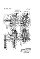
- Fi' 3 is a front "elevation of the power win er of m invention with parts broken away to clear y illustrate the winding spindle section to illustrate a portion oft wcombmed material su aries and the raking and other parts associated'therewith.
- Fig. 4 is adeft end" view Fig. 3f V Fig. 5is a rear view of Fig. 3- cover of the enclosing casing clearly illustrate the'interioi' mechanism.
- Fig. 6 is 'a sectional view of the power 1
- Fig. 7 is a sectional view along the line Fi 8 is a fra mentary view of the power win er illustrating the driving clutch in a disengaged position.
- Fig. is a fragmentary view partially in e counting mechanism.
- Fi .-10 is a front elevation [of one of the tension devices whic er or tin foil.
- y 4 7 W ig. .11 is a left end view of Fi 10.;
- Fi 12 is a "sectional view a ong the line 12- 2 of Fi 11 illustrating the tension de-, means associated with the material supporting spindle;
- Fi 18 is a sectiohal view along line 13-13 of Fig. 10. l
- Fig.1. is a site elevation of the power con-' porting'spindles and ed and a collar 25having -;supports a rpll of,
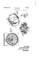
- Fig/14 is a view of the counter device of mg invention.
- ig. 15 is a sectional view along the'line 15-15 of Fig. 14.
- Fig. 16 is a perspective view of the rippin'g device wluch is associated with the riving means of the counting mechanism, and
- a suitable cnc osing casing or'housing I which encloses the mechanism of ti same.
- a pair of bearings 3 and 4 in the orifices 5 and 6 in the respective ends of the housing H rotatably support a spindle shaft 2.
- a sprocket 7 is slidably and loosely supported on-one end of the spindle shaft 2 and transmits motion to the. spindle shaft 2 through the medium of suitable'clutch mechanism C as will be more fully hereinafter described.
- the spindle shaft 2 has a worm portion 8 cut thereon "and fneshes-with a worm gear 9 loosely supported on a hollow transverse shaft 10 rotatably' su )ported in bear-;
- a cup shaped gripping member 15 is provided with a peripheral slot 16 extending through the Wall of the member 15 and another slot 17 at right angles to the pe h ripheral slot 16 is cut in the wall of the member tointcrsect the peripheral slot 16.
- the inside diameter of the cup she ed member 15 is eccentrically disposed relative to the outside diameter-of the cu member v15, and the slot 17 in association with the; peripheral slot 16, and the reduced wall portion 18 of the cup ith the rear 19 and 20' for purposes as will presently removed to described.
- the member 15 is provided with area!- Wardly extending collar 21 secured thereto by suitable screws and an integrally formed rearwardly extending sleeve 22 provided with an F orifice 23 of a size to permit the cap member 15 to he slipped on to the hollow-shaft 10.
- the hollowshaft 10 and orifice 23 in the sleeve extension 22 are provided with'keyways and a key cup member 15 to the hollow shaft 10 so the 24 resting in the key ways secures the same will rotat'ewith the shaft 10 when it is rotated.
- the end 10of theshaft 10 is thread- 4 screw threaded engagement with the threaded portion 10 of the member 15' on the shaft 10 against longitu inal movement.
- worm gear 9 is rovided with ccunterbore 26 of a size to receive the split or ipping rtion ofthe cup member 15 an the dept of the counterbore 26 in the worm gear 9 1s substantiall the same as the split or grip in portion ormed by the wings 19 and 20w 1 rest wholly within the counterbore 26,.
- a second diskmember 32 having an integrally, formed sleeve extension 32 is provided with an orifice of a,size' to permit the same to be slipped over the sleeve extension 29 of the disk 29 and an arm extension 33 integrally formed with the disk 32 is'provided with an arcuate end 33' which coincides with the pe- "ripheral edge of the'disk29 and this arm 33 and disk 29are operatively associated with each other for purposes to be presently described.
- a coil spring 34 having one end secured to a pin 35secured to the disk 32 and its other end looped around a stop-pin 35' secured to the disk 29 and secured to a pin.
- a cup shaped cover 38 provided with a central orifice I through which they end of the hollow shaft 10 extends is secured to the casing by means of screws 39 which pass through ori ces in tabs 40 integral with the cover 38 and have threaded engagement with tapped orifices in the housing H, and the cover 38 when in position as just described maintains the disks 29 and 32 on the hollow shaft 10 against longitudinal movement.
- An indicator arm 42 is secured to I the end of the'hollow shaftlO, which protill trudes through the central orifice in the cover 38, by means of a 'key 41 which fits into a keyway in the shaft 10' and orifice in the indicator arm 42.
- the indicator arm is provided with a bifurcated depending'portion and a screw 42 clamps the said arm 42 on the shaft 10 against movement.
- a graduated dial 43 is secured to the cover 38 and in amociation with the'indic'ator arm 42 indicates the numibenief turns (of operation) of the-' indlu shaft for purposes as will presently e de scribed.
- the plate 45 is provided with a pair of diametrically oppositerorifices 52 and 53 which are in alignment with a pair of orifices 54 and 55'extending through the 5 base56 of the cup member'15.
- a screw 57 provided with a hemispherical head 57' rests trill a,concave countersunk portion '58 around the orifice 52 in the plate 45 and" extends 1 through the aligned orifices 52 and 54in the plate45 and the base 56 of the cup member 15.
- 'A forked shaped member 59 extends through the oblong orifice 55 in the base 56 of the cup member 15 and an upwardl threaded stud 59 integral with the forks member 59 extends into the'aligned orifice 53 in the plate 45 and a hemispherical shaped extendin nut'60 having threaded engagement with the 7 Stud 59 rests in a concave countersink 61 around the orifice 53.
- a trigger rod 62 which extends through the hollow shaft 10 and a pin 63 secured thereto intermediate of its ends extends through longitudinal slots 64 and 65 in the sleeve extension 22 of the cup member 15 and hollow shaft 10 and lies between the legs 66 and 67 of the forked shaped member 59 which protrudes through the orifice 55' of, the base 56 of the cup member 15.
- the screw 57 extends through the orifice 54 in the base 56 of the cup member 15 and this protruding portion supports a coil spring 68 which rests between the base 56 of the on an adjusting nut 69 which has threadedengagement with the screw 57 and is used'for placin the spring 68 under preper'compreshe plate 45 pivotally supported insion.
- the cup member 15 is normally tilted from its horizontal plane as illustrated in Fig. 15, due I to the compression'of the spring 68.
- the forkedmember 59 between which the pin 63 secured to the trigger rod 62 is secured is ⁇ linked withthe'plate 45 by means of a plate 7 0 provided with a pair oforifices 71 through whlch thele s 66 and 67 of the forked member 59 exten and nuts 72'havin threaded en.- gagement with the legs 66 an 67 position member 15 and to the can gage the respective faces 74'and of the slot 17 and spring or spread the wings 19 and 20 of the split portion of the member lti'and is the s )lll) portion of the member 1!) lies wholly within the counterbore 26 of the worm gear 9, the expansion of the wings 19 and 20 of the split portion of the member 15 causes the circumferential faces of the wings 19 and 29 to firmly grip the circumferential face of the counterhore 26 of the worm gear i)
- a spiral leaf spring 78 is provided and has one end secured to the housing H by suitable means and its other end secured to the sleeve extension 21 secured to the base 56 of the cup member 15.
- the tension of the spiral spring 78 is such as to maintain the tongue exten-' sion 15' integral with the cap member 15 against an adjustable stop 79 sup iorted ina block 80 secured tothe housing I Y
- the cup member 15 as before described is secured to the hollow shaft 10 and through the agency of the split portion which forms the wings "19 and 20 normally grips the circumferential face of the countcrbore 26 in the worm gear 9.
- the disk 29 which is connected to the hollow shaft 10 by nleansof the pinsjlt) secured thereto and which extend into the orifices 31 in the flange 28 integral with the hollow shaft 10 to eause'the same to rotate therewith is o eratively associated with a detent 82 pivotal y secured to the front wall of the housing H to control the clutch mechanism C for connecting and disconnecting the spindle shaft 2 from the source of power for rotatin the same.
- a pair of cars 83 integral witi the housin H pivotally support a stub shaft 84 one on of which has secured thereto an arm 85 extending parallel with the detent 82nd A oke member 86 straddling the detent 82 and arm 85 link them together and a leaf s ring 87 resting between the bottom edge of the detent 82 and the top-edge of the arm 85 maintains the detent 82 and arm 85 in spaced relation and in association with the yoke member 86, and any movement of the detent 82 will be transmitted to the arin 85.
- a clutch arm 90 is secured to the stub shaft be- -'which is pivotally secured to the housing H.
- ratchet teeth 99. .A collar is keyed to the sleeve 93 and the end of which is provided with ratchet teeth 191.
- the tension of the leaf 3 ring 96 supported between the flange 94 an the thrust bearing 97 is such as to force the collar 92, supporting the sprocket 7, to the left with reference to Fig.
- a condenser comprises plates of foil and a dielectric between the lates and comprises a predeter mined num er-of turns for agiven capacity.
- the disk 29 is'provided with a notch 104 in its per pheral edge which is spaced a predetermined distance from the zero or indicatiom' mark 103 into which the nose 102 of the detent 82 drops after a predeterminednumber of turns have been placed u on the winding mandrel to arrest the rotation of the winding spindle 2.
- a split chuck 105 is associated with the winding spindle 2 and through the medium of a collar 106 having threaded engagement with the end of the winding spindle 2 en-- gages the split chuck .105 to clamp a suitable winding mandrel (not shown) upon. which .the' condenser is wound.
- the rolls of tin-v foil which form the plates and the dielectric are supported by the tension devices T secured to the housing HO which is supported onthe pedestal P.
- the foil and dielectric are brou ht out through the ripening in the housing 7 O- and attached tothe winding mandrel secured to the winding spindle 2 by the chuck .105.
- the detent 82 pivotally se-' cured to the housing H is normally held in .araised positioh withiits nose ,102 engag ing the peripheral-edgeof'the disk 29 in.
- the removable cover 14 of the housing H is provided with a pair of integrally formed ears 107, and bearing screws 108 having threaded engagement with tapped orifices in I the respective ears 107 rod 109 between them.
- 11 arm 110'secured to the rod 109 extends through "a suitable orifice in the removable cover- 14, and by means of a link connection 111, which extends through a suitable orifice in the end face of the housin H the depending arm 112
- the movement of'the arm 110 to the left pivot screws-108 to move anarm 113 secured to the rod.109' against the tension of a coil spring 11 1 supported on a screw 115 which passes through suitable orifices in the removal cover 14am ⁇ free end of the arm 113.
- the ratchet'clutch teeth 99 and 101 of the clutch mechanism C are now in mesh an the, operator having secured the foil plates and dielectgic tothe winding mandrel secured to the. winding spindle 2 the rotation of the winding spindle 2 is brought about by the operator stepping on the starting pedal (not shown) and through the medium of clutch mechanism' GM, operated b the starting pedal, ower is transmitted rom the power supply S to the sprocket wheel of the clutch mechanism 0 associated with the spindle shaft, through the medium of the sprockets and chain drives associated with the power supply and clutch CM.
- the said 4 disk 29' is ⁇ rotated in the direction of the arrow with, reference to Fig. .3.
- the stop arm 33 integral with disk 32 supported on thelsleeve extension of the disk 29 normall engages the stop pin 35' secured to the 'dis 7 i 29 as b efore described.
- the disk 29 conivotally support a g .to move to the left with reference to Fig.
- a atch plate 120 secured to the forward end of the detent 82 by suitable screws 121 is provided with a, nose 122 which over-hangs the peripheral edge of the disk 29 and co-operates with the arm 33 integral with disk 32 supported'on the sleeve extension of the disk 29, and is o eratively associated with the notch 104 int 0 disk 29.
- the notch 104 in the peripheral edge of the disk 29 is located along its peripheral edge relative to the zero or ndication mark 103 thereon, depending upon the number of turns to be placed on the winding mandrel before the terminals of the respective plates-of the condenser are inserted, and for the purpose of illustration and description the notch 104 in the disk 29. is spaced relative to the indication mark. 103 to permit fifty turns to be placed on the windmgmandrel. But itfis to be 'hnderstood anythe face of thedisk 29 with its arouate end 33' covering the notch 104 in the disk 29.
- the arm 33 which covers the notch 104 in the disk 29 is engaged by the nose 122 of the latch late 120, secured to the' detent 82, andas the isk 32 with which the arm 33 is integral is loosely supported on the sleeve extension of the disk 29 this engagement of the latch plate 120 with arm 33 arrests rotation of the arm 33 but the disk 29 continues to rotate.
- the arcuate end'33' of the arm 33 is no longer covering the notch 104 in the periphera edge of the disk 29 and the nose 102 of the detent 82 which is now in position overthe mum 104 and ready to drop. in, as clearly illustrated in Fig. 8 by means new to be described.
- the arm 113 secured to the pivoted rod 109 when moved into position as previously described places the spring 114 'assoeiated therewith under compression and the instant that the nose 102 of the detent 82 is positioned above the notch 104 in thc'peripheral edge of the disk 29 the spring 114 assocmted with the arm 113 moves the sameinward with reference toliig.
- he movement of the stub shaft 84 causes the mm secured to the same to move in.a downward direction with reference to Fig. 3 and this movement of the arm 85 is transmitted to the detent 82 by the link 86 which connects the arm 85 and detent 82 to force'the nose 102 of" the same into the 'notch 104 in the peripheral edgeof the disk 29.
- the disconnection of the ratchet teeth of the collar 92 and the ratchet teeth 101 arrests further rotation of the winding spindle and this permits the operator to'insert the terminals of the res ectlve lates of the condenser.
- the end 135 of the lever 130 engages the end of the plate 132 when the same is do ressed to move the slidable plate 132 upwar
- the movement of the detent 82 causes the nose 122 of the latch plate 120, secured to the detent 82, todisengage the arm 33 and also raise the nose 102 of the detent 82 clear of the notch 104 in which the same is resting.
- the rotation of the stub shaft 84 causes the clutch,
- T 10 arm 33 integral with the disk 32 was held due to its engagement with the nose 1.22 of the latch plate 120 as before described to place helical spring 34 associated therewith under additional tension andthe instant that the latch plate 120 disen ages the arm 33, due to the movement of the etent 82, the arm 33 is moved clockwise under the tension of the spring 34 until the stoparm 33, integral with lllll the disk 32, engages the stop pin 35 secured to the disk 29.
- the operator now releases the lever 130 and the same is restored by a coil spring and this permits the sliding plate 182 to restore.
- the arcuate end 33 of the arm 33 againcovers the notch 104 in the peripheral edge of the disk 29, and when the level 130 is released, the'afm 85 and detent 82 are moved down under the influence of the spring 114.
- the nose 122 of the latch plate 120 now rests on the 'arcuate end 33' of the arm 33 arid.
- the machine is "again set to permit the rotation of the .wihdingspind'le2 and the operator now steps on the starting pedal and power'is transmitted to the winding spindle'2' as before described bringing about the rotation of the hollow shaft 10 and disk 29 connected thereto.
- the disk 29 con- 30 tinuesto rotate until the edge of the nose 102 of the detent 82 passes the edge of the notch 140 in the peripheral edge of the disk 29 atwhich time the detent82'drops into the notch 140 under the influence of the spring 114 asso-' ciated withthe arm 113 as before described causing the clutch arm 90 to be moved as previouslydescribed to bring about the disengagement of the clutch ratchet teeth 99 and 101 and arrest further rotation of the winding spindle 2.
- the conden'ser suppprted on the wind ng mandrel having received the required fiumber of turns,the operator finishes the same before removal.
- the operator next-depresses the lever 130 which causes the 3" clutch arm90 to' bemoved asbefore described to permit the 'collar 92 to be moved under the influence of the spring 96 to cause the ratchet teeth 99 of the collar 92 to mesh with the ratchet teeth 101 of the collar 100 secured to the spindle shaft 2.
- Thespindle shaft 2 again. rotates and continues as long as the lever 130 remains depress'ed.- After the protectingcovering has been placed upon the wind ng the operator releases the lever 130 permitting the teeth 99 of the collar 92 to disengage the ratchet-teeth 101 ofthe collar 100 and further rotation of the spindle 2 is stopped 'as is readily understood from the o previousdescriptioh.
- the stub shaft 84 raises the arm 85 and due to the link connection 86 between the arm 85 andgfletent'82 the detent 82-is also raised.
- the nose 102 of the-detent 82 is moved to'rotate the stub shaft 84. Th s movement a out of the notch 140 in the peripheral edge a 0f the disk 29 aiid permits the restoration of t hehollou shaft 10 and its supported parts.
- the faces 50 and 51 of the actuating head 46 assume a position parallel with the faces 74 and 75 in the slot 17, the wings 19 and 20 move from their expanded to a collapsed position under the influence of the tension under which they were placed when expanded.
- the wings 19 and 20 release their grip from the? circumferential face of-the counterbore 26 of the worm, ear 9 and as the spring 78 was placed um er tension as the cap member rotated the spring 78 now returns the on member 16 and shaft 10 to which it is secured and disks 29'and 32 and indicator 42 to their normal position with the tongue extension 15' of the cup member 16 engaging the stop 7 9
- the operator new releases the pressure which was, applied to the trigger rod 62 to permit the same to assume its normal position.
- the spring 68 supported on the screw 57 was placed under tension when the plate was moved to a horizontal position and as soon as the pressure is released from the trigger rod 62the plate 45 is moved to its angular position under the influence of the spring 68.
- the in 63 secured to the trigger rod 62 engages t 1e plate 70 supported on the legs 66 and 67 of the member 59, and the movement of plate 46 to its normal angular position causes the member 69 to be moved forward with reference to Fig. 7 to move the trigger rod 62 forward to its normal position.
- The-plate 45 assuming its angular position again places the faces and 51' of its operating head 46 in an angular position relative to the faces 74 and 7 5 of the slot 17 in the cap member 16 causing theedges 7 6 and 77 of the operating heads 46 to a ain engage the faces 74. and 7 5 of the slot 17.
- This engagement of the edges 76 and 77 of the operating head 46' with the faces 74 and 75 oi the slot 17 causes the wings 19 and 2 0 of the cup memher 15to againexpand and grip the counterbore26 in the gear 9.
- the trigger rod 62 having been restored, the arm 116 secured to v the ivoted rod 109 movesup with reference to Fig.
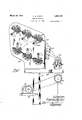
- Figs. 1 and 2 I illustrate the complete condenser winding machine of my invention and it comprises a suitable pedestal'P which supports a bed plate or table BP uponwhich is secured the power winding machine: PW already described in detail;
- a plate 160 secured to the pedestal P intermediate of its ends supports a suitable power source P-S which comprises a motor and a suitable s ecd reducing mechanism.
- a suitable clutc mechanism CM is secured to bottom of the bed late BI and is controlled by a ed al not shown).
- a suitable chain drive and sprockets associated with the power -source PS and clutch mechanism CM,
- plower is so lied to the clutclimechanism G
- a suita e chain connects the sprocket 161 of theeclutch mechanism GM to the sprocket 7 connected with the winding spindle 2 of. the winding machine'PW an ower is transmitted to the windinispin le 2 when the clutch CM is actuated y the operator of the machine through the medium of the starting pedal.
- a housing H0 is also supported on the bedplate BP and secured t iercto and positioned behind the power windin machine PW and secured to the outside ace of the housing wall 162 is a plurality of comspindles for supportingithe rolls of tin foi and tissue paper and tension devices '1. As all the devices are similar in construction a detailed description of 12px; will gufiipie. d1
- 1e *com ine pa er supportin spin e and tension device T illustrated in detail in Figs. 10 to 1B constitutelve compfises a s indle supporting housing 168 provided wit substantially circular and ieces 164 and 165 which are provided wit counterbores 166 and 167 adapted to receive the ball race retainers 168 and 169; and ball bearings 170 and 171 which rest in these retainers 168 and 169 and to rotatably support a pa er reduced portions 173 and 174 o the retainers 168 and 169 rotatably support the tension arm 181 which is for ur 10808 as will presently be'described.
- co lar 182 having a threaded sleeve extension 183 engages a orifice in the tension arm 181 to enprotrude through orifices in the ends c ball bearings and 176 sup orted on the gage a plate 185 which rests against the ball ear'ing 176 in the counterbore 178 of the tension arm 181. and serves to adjust the tension arm 181 so ported on the reduced pottions 173 and 1 4 of-the retainers 168 and 169 to revent lateral movement ofthe same.
- An ad ustable plate 186-having threaded enga ement with the-threaded end 187 of the fices in the wall 162 of the housing cure the housing 163 and the tension arm' 181 supported therein to the wall of the housing H0.
- the substantially circular end 164 of the housing 163 extends into an orifice 194 202 extcndinto these orifices 203
- the plug in the wall of the housing HO and the spindle 172 supported in the housing 163 protrudes into the housing HO to which the devices T are secured.
- the sleeve 196 secured to the s indle end 172 is adapted to receive a supp y roll of tin foil or tissue paper for delivery to the winding machine mandrel, of the winding machine PW, and I provide novel means associated with the sleeve 196 for securing; the roll of supply material thereon againstdisplacement and which I will now 7 I describe.
- a plug or disk 1980f a size to permit the same-to fit in the sleeve 196 is securedtherein intermediate of its ends and a plug 199 fitting in the sleeve 196 at its outer end and secured therein serves to support an adjustable shank 200.
- the sleeve 196 is provided with a pair of slots 201 diametrically opposite each other to permit the insertion of a pair of bowed leaf sprin s 202, the ends of which engage respective y the plug 199 and the end of the collar 195 secured to t e spindle end 172.
- the disk 198 which is secured in the sleeve 196 asbefore described, is located therein to position it'substantially intermediate of the ends of the diametrically opposite slots 201, and is provided with a air of diametrically opposite orifices 203 w 'ich are aligned with the slots.
- a threaded orifice 205 which is adapted to receive the threaded portion200' of a shank O to se- 200 and an orifice 206'in the disk 198 is ada ted to receive the end of the shank 200.
- ends of the pins 204 which are secured to the leaf s ring 203 are rounded and extend into the orifice 206 in the disk 198 and are ada ted to be en aged by the tapered portion 20 of the shan .200.
- the bowed'portions of the springs 202 extend into the slots 2010f the sleeve 196 as illustrated in Fi 11, and are shown in the normal or unflexe position with the pins 204 secured thereto and. which extend throughthe orifices 203' in the disk 198 enaging the reduced end 208 of the shank 200.
- he shank 200 is provided with asquare head 209 for theapphcation of a suitable wrench by which the shank 200 may be turned.
- a suitable wrench by which the shank 200 may be turned.
- the shank 200 is turned by means of a suitable socket wrenchen aging the head 209 in a direction to cause t e tapered portion 207 of the shank 200'to engage the rounded ends.
- a suitable brake mechanism B is associated with the tension arm 181 and com rises a pair of brake arms 221 and 222 provi edwith intermediate substantiall semi-circular
- the free end of the tension arm 181 is prohousing by suitable screws.
- a brake drum 230 secured to the shaft 172 is adapted to cooperate with the semi-circulaf leather lined portions 221' and 222' of the pivoted arms 221 and 222 and I provide adjustable spring means associated withthe free end 231 and 232 of the brake arms 221 and 222 to regulate the pressure applied to the brake drum 230 by the brake arms 221 and 222.
- the spring means comprises a threaded pin 233 which extends through aligned orifices in the free ends 231 and 232 of the arms 221 and 222 and a helical spring 234 supported on the protruding end of the pin 233 may be compressed by an adjustable nut 235 which has threaded engagement with the pin 233.
- a plate 236 secured to the wall 162 of the housing HO by screws 236v has secured to it a stud 237 which rotatably supports a cam member 240 to which is secured an arm 238.
- the cam member 240 rotatably suppored-on the stud 237 rests between the free ends 231 and 232 of the brake arms 221 and222 and is provided withcam faces 241 and 241 which when positioned between the arms221 and 222 lie substantially parallel
- the combined paper supporting spindles The rollers 218 secured to the tension arms 181 and the paper supporting spindle sleeves 196 extend respectively through arcuate slots 213and orifices 194 in the wall 162 of the housing HO into the interior of the housing.
- I have shown six devices T secured" to the wall of the housing HO which provide spindles for supporting two rolls of tin foil and four rolls of suitable dielectric such as tissue aper.
- any num er of tension devices may be provided depending upon the number of layers of paper and foil to be used in'the condenser.
- the respective ribbons of material are fed over the respectiv rollers 218, supported on the tension arms 181, and through the square opening in the wall of the housing HQ.
- the ribbons of material are then fed over rollers 270 supported on an adjustable rack 271, secured to the front wall 211 of the housing HO, to the winding mandrel supported by the spindle shaft 2 of the winding machine PW.
- the cam member 240 is provided with a sleeve extension 240 and the arm 238 secured to the cam 240 is providedwith an orifice of a size to fiton the sleeve extension 240' ofthe cam 240 and a depending split portion integral end 245 of the arm 238 and the other end being threaded and having threaded engagement with a tapped orifice in the member 242 I pinned to the tension arm 181.
- thumb piece 246 secured to'pitman 243 is for the purpose of rotating the pitman 243 to adjust the cam member 240 secured, to the stud 237 relative to the arms 221 and 222-of the brake
- An arm 247 pivotally' secured to the tension arm 181 extends through an orifice 248 in the housing 163 andlsup t wsprivn 1 49 and an'adjustable nut 250 having thr d d on the ribbon of material and this pull moves the tension arm 181 to the right with reference to Figs. 10 and 12," and the arm 238 being linked to the tension arm 181 by means of the adjustable pitman 243 and member 242 the said arm 238 is also moved to the right.
- the 'movement of the arm 238 causes the cam 240 to rotate about the supporting stud 237 to place the respective edges 260 and 261 in engagement with the respective inner faces of the brake arms 221 and 222.
- the spring 234 supported on the pin 233 was compressed when the rms 221 and 222 were moved as before described and the instant that ca-m edges 260 and 261 disengage the arms 221 and 222 the spring 234 again presses the arcuate leather lined ortions 221" and 222 into engagement wit 'the brake drum 230 toinstahtly stop the rotation of the spindle 17 2 which has secured to it the sleeve 196 andwhich supports the roll of supply'material.
- the instantaneous stopping of the spindle 172 prevents any over run 0 the roll of material supported on the sleeve 196 .and the spring 249 1s so adjusted that it maintains the arm in a position-so as to take up any slack which ma be inthe ribbon of matenal after the win ing machine PW is automaticall stopped.
- Varying t icknesses or gain es of material are used in the manufacture o condensers so I have provided .means whereby the are of movement of the tension arm 181 may be regulated to afi'ect the movement of the 'cam 240 to operate the brake mechanism B.
- the link connection between the'arm'238 and the tension arm 181 is lengthened through the medium of the adjustable pitman 243 of the link, the arm 238-secured to the sleeve ex-, tension of the cam 240 is moved to .the left with'reference to Fig. 10, and this movement of the arm 238 also affects movement of the cam 240 to place the respective cam faces 241 and 241' substantially arallel with the -i-'n-.
- the 1 springs 234 and 249 may also be adjusted by means of the respective adjustin nuts'235v and 250 to place the springs/mnder greater tension so that a considerable amount of pu ll by the ribbon of materiah passing over the roller 218 must be applied to overcome the tension of the springs 234 and 249'to allow the arm 181 to move and cause the arm 238 which is linked thereto toactuate the earn 240 to force the brake arms 221 and 222 apart.
- This adjustment of the tension arm 181 may p 'be used where the material used is of a heavy 1 gauge to maintain th tension arm 181 under proper tension to ke p the-ribbons of material which pass over the rollers 218 of the respective tension arms 181 taut between thesaid rollers 218 and the winding mandrel during the winding operation of the condenser.
- I i VVhenthe link connection between the arm 238 and tension" arm 181 is shortened the arm 238' is movedto the right with reference to Fig. 10 causing the cam 240 to which the arm 238 is secured to be rotated about its supportin g stud 237 to place the-faces 241 and 241- in an angular. position relative to the inner faces 9 of the'brake arms 221 and 222 and move the cam edges 260 and 261 into engagement with the respective, faces of the arms 221 and 222.
- tension arm 181 is required to overcome the tension of the springs 234 and 249 to allow the arm 181 to move and cause the arm 238 which is linked thereto to actuate the cam 240 to force the brake arms 221 and 222 apart.
- This adjustment of the tension arm 181 may be used when the material used is of a li ht gauge to maintain the tension arm un er proper tension to keep the ribbons of mate- .rial which pass over the rollers 218 of the winding simultaneously turns of different materials upon a winding spindle, and means including a disk having spaced notches in its peripheral edge, a detent associated with sa1d disk, an arm loosely supported by said disk normally covering the first of said notches and a device on said detent for holding said arm to permit said detent to enter said notch for automatically stopping the rotation of said winding spindle at predetermined points in the winding during the time said winding spindle is making said predetermined number of revolutions.
- a winding machine of the character described including means for automatically" winding turns of different materials upon a winding spindle simultaneously, a disc having a pair of notches in its peripheral edge, a detent associated with said disc, an arm loosely supported by said disc and normally covering one of said notches, a latch on said detent for holding said arm to permit said detent to enter said notch to automatically stop the rotation of said winding spindle at intervals while said winding spindle is making said predetermined number ofrevolutions, and'resetting means to permit the rotation of said winding spindle after each stop.
- a winding machine the combination with a winding spindle, driving means, clutch mechanism associated with said Winding spindle for connecting and disconnecting said winding spindle to and from said driving means, setting means adapted to be driven by said winding spindle comprising a disk having a pair of notches in its peripheral edge and an arm covering one of said notches, a detent having a latch for holding said arm to clear said notch to permit said detent to enter said notch in said disk after a predetermined extent of movement of said setting means to operate said clutch mechanism to render sa1d drlvmg means inoperatlve, and
- a winding machine the combination with a winding s indie driving means for said winding spin is, a c utch associated with said winding s indie for connecting and disconnecting sai winding spindle to andfrom said driving means, setting means driven by said winding spindle and adapted to permit said winding s indie comprising a disk provided with n6tc es spaced at a predetermined distance in the peripheral edge of said disk an arm loosely supported said disk an normally covering the first of said notches, a detent associated witlisaid disk said'detent carrying a latch adapted to hold said arm to clear said notch to permit-saiddetent to enter the first of said notches'after a reg determined extent of travel of saiddis to operate said clutch to render said drivingmeans ino erative, and means operative to reset said etent to ermit another predeterminedtravel of said disk beforesaid detent enga es the other of said notches.
- a winding machine the combination with a winding spindle, driving means for ,said winding spindle, a clutch associated with said winding spindle for connecting and disconnecting said winding spindle to and r from said driving means, setting means driven by said winding spindle and adapted to permit a predetermined number of revolutions of said winding spindle comprising a 35 disk provided with note es spaced at gradetermmed distances in the peripheral e ge of said disk, a detent associated with said disk, an armloosely supported on said disk nor- .maliy covering the first of said notches, a latch plate on said detent adapted to engagesaid armafter a predetermined extent of travel of said disk to clear said notch to pera predetermined number of revolutions'oF -fo'r stopping said winding machine when a predetermined-number of turns'of said materials have been placed upon said winding spindle.
- An automatic winding machine for si- .70 multaneousiy placing layers of materials upon a winding spindle, automatic-means comprising a disk having notchesin its peripheral ed'ge, clutch mechanism, an arm supported on said disk and normally covering one, of said notches,a detent associated with, said disk, means for engaging said arm to clear said notch to permit said detent to enter said notch to actuate said clutch mechanism for stopping the ,rotation of said windin 8 spindle when a predetermined number 0% turns of said materials have been placed upon said winding spindle, an means for there! after continuing the rota ion of said winding spin dle.
- An automatic winding machine for placing simultaneously a predetermined number of layers of materials upon a. winding spindle, automatic means comprising a disk having. notches in, its peripheral edge, clutch mechanism, an arm supported on said disk and normally covering one .of said notches, a detent "associated with saiddisk, means for engaging said arm to clear said, notch to permit said detent to'enter said notch to actuate said clutch mechanism for stopping said windingmachine when said ⁇ predetermined number of turns of material ave been placed upon'sa'id winding spindle, and means mal. 7 r 12.
- An automatic winding machine for simultaneously placing materials in layers.
- a 'windin'g sgindimauto'matic means comprismga disk aving notches in its pa. 1 ⁇ ripheral edge, clutch mechanism, an-arm sup 'ported on said disk and normally covering mit said detent to drop.
- An automatic winding machine for'siinultaneously placing layers of materials upon a winding spindieyand automatic means comprising a, disk having 'notchesin its peso ripheraledge, clutch mechanism, an arin supported on said disk and normally covering one of-isaid notches, a detent associated with said disk, means for engaging said arm .to clear said notch to permit said detent to enter 5 said notch to actuate said clutch mechanism rmit said disk, means" for engaging said arin to I clear said notch to permit said detent to enter said notch to actuate said clutch mechanism. for discontinuing the rotation of said'winding spindle after it has made a predetermined number of revolutions, and operator controlled means for restoring said automatic machine-to normal.
- An aiitomat-ic winding machine for simultaneo usly placing layers of material upon a winding spindle, power means for rotating said spindle, automatically controlled means comprising. a disk'havingnotches in its peripheral edge, a detent associated with said disk, an arm loosely supported on said disk and normally covering one of said notches,
Landscapes
- Engineering & Computer Science (AREA)
- Power Engineering (AREA)
- Manufacturing & Machinery (AREA)
- Microelectronics & Electronic Packaging (AREA)
- Mechanical Operated Clutches (AREA)
Description
March 22, 1932. M GROUT I 1,850,102
WINDING MACHINE 'Filed Aug. 24, 1927 Sheets-Sheet l ZZYZ/ 227472? 2 17552 5222.
" F ,UZWEL March 22, 193 M R UT 1,850,102v
IIIIIIIIIIII NE Filed Aug. 24, l92'7 e Sheets-Sheet 2 v Ill" 1 W a HETYZTYEE'DT WW Y March 22, 1932. B. GROUT 6 Sheets-Sheet I5 WINDING MACHINE Filed Aug. 24,
March 22, 1932. M. B. GROUT WINDING' MACHINE Filed Aug. 24, 1927 6 ShQBtS-ShGet 4 171/51? 011' HETTFYEEFUZT E- /5.a.
March 22, 1932. M. BfGho uT WINDING MACHINE Filed Aug. 24, 1927 6 Sheets-Sheet 5 March 22, 1932.
M. BL GROUT WINDING MACHINE 6 Sheets-Sheet 6 Filed Aug. 24, 1927 27/227702? JYEWTZEEIEZ'Z'T E47 .6.
:Patented 22; 1932 UNITED/STATES PATENT OFFICE man'rm 13. snow, or cnrcAeo, rumors, assrenon 'ro KELLOGG- swrrcnsoann AND a sur'PLY comm, or cmonco, rumors, A conrom'nonor rumors wm'nme mourns."
mime filed August 24, 1927. Serial No. 214,992.
My invention relatesto winding machines and has more particularly to do with condenser winding machines in which suitable means are provided for winding the material consisting of foil or other material which form the plates and a suitable dielectric such as tissue paper into-rolls to form condensers which are well known in the at An object of my invention is the provision of a power winding machine of the above'type whlch will iefliciently wind'condensers.
Condensers are wound to a predetermined capacity and it is therefore essential thatthe proper number of turns are laced on a suitable winding mandrel. A ter a predetermined number of turns have been placed on the winding mandrelthe'machinemust be stopped to permit the insertion of the terminals for the plates of the condenser andthen started again to place the remaining turns thereon for a'given capacity; The winding of condensers at the present time is a manual operation in which the operator fur nishes the power for rotating the winding spindle and in addition to this task watches the counter mechanism associated with the winding spindle to see that the proper num ber of turns are placed on the winding spindie. It is readilyapparentthat owing to error on the part of the o erator the machine may be stopped before t e required number of turns are placed on the winding spindle or more than the required number may be placed on this winding spindle before the machine is stopped.
To overcome this deficiency of manual windin of condensers I have devised a counter mec anismwhich in association with the 'winding spindle of the winding machine of my invention provides means whereby after a predetermined number of turns have been placed upon the winding spindle which is power dr1ven,- it is automatically stopped to permit the insertion of theterminals of the condenser.
Another feature of my invention is the provision of means which when actuated by ing turns to be placed on the winding man drel when the winding spindle is again autoinatically stopped.
"Another feature of my invention is the provision of interchangeable means associated with the'countiii mechanism whereby any number of stops 0 the winding spindle may be accomplished and whereby anynumher of turns may be initially placed onthe winding spindle before the same is automatically stopped and in which the means permit the winding spindle to again be started.
Another feature ofmy invention is the provision of clutch mechanism associated with the winding spindle which is operated to instantly disconnect the winding spindle from the power supply when the means associated with the countermechanism functions after a predetermined number of turns have been placed upon the windings indle.
A Still another feature 0 my invention is the provision of combined materialsup'porting'spindle and tension devices which 'support the rolls'of material which arefwound upon the winding spindle of the winding machine of my invention. i
Another feature of my invention is the provision of a tension arm'in association with material supporting spindle which function to keep the material between the winding spindle and the tension arm roller over which the material passes taut and at the proper tensionduring the winding operation.
Another feature of my invention is the provision of novel brake means associated with the material supporting spindle which is tension onthe material being. delivered to. the winding spindle ceases, toprevent anyover-run of the material supported thereon.-
Still another feature of my invention is the provision of adjustable means for regulating the tension of the tension arm-of the combined material supporting spindle and tension device to permit the use of material of speed companyingdrawinfis vence characters 1n t e varying thickness, this, of K course, depending upon the type of condenser being built.
Another feature of my invention is the provision of means which maintains the layers of foil and paper in alignment while being wound into a spool.
Another feature of my device is the pie vision of means for smoothing out the paper and foil as it is being wound, so that no wrinides a pear in the same after it is wound upont e mandrel.
By rotating the spindle at a'constant, speed I am able to form re ular coils'having uniform stress between t e layers, and I am further enabled to greatly speed up the winding b means of my lllltOlIllltlCBtO mechanism. Further the coils wound are a lot uniform capacity since the tension on the material woundis always the same and the number of turns wound isalways the same.
The above features as well as others not s ecifically pointed out will be more fully ascribed in the ensuing specification and appended claims.
or a more complete understanding of my invention references may be had tothe acin which like referseveral views denote like parts and in which denser winding machine of my invention.
Fig. 2 is a I'GVGIBGSldGGlGVlLtlOIl of Fig. 1
illustrating how the paper and foil rolls are with the same. I
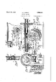
Fi' 3 is a front "elevation of the power win er of m invention with parts broken away to clear y illustrate the winding spindle section to illustrate a portion oft wcombmed material su aries and the raking and other parts associated'therewith.
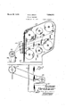
Fig. 4 is adeft end" view Fig. 3f V Fig. 5is a rear view of Fig. 3- cover of the enclosing casing clearly illustrate the'interioi' mechanism.
Fig. 6 is 'a sectional view of the power 1 Fig. 7 is a sectional view along the line Fi 8 is a fra mentary view of the power win er illustrating the driving clutch in a disengaged position.
Fig. is a fragmentary view partially in e counting mechanism.
Fi .-10"is a front elevation [of one of the tension devices whic er or tin foil. y 4 7 W ig. .11 is a left end view of Fi 10.;
Fi 18 is a sectiohal view along line 13-13 of Fig. 10. l
Fig.1. is a site elevation of the power con-' porting'spindles and ed and a collar 25having -;supports a rpll of,
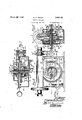
' shaft 10 secures the cu Fig/14: is a view of the counter device of mg invention. ig. 15 is a sectional view along the'line 15-15 of Fig. 14.
Fig. 16 is a perspective view of the rippin'g device wluch is associated with the riving means of the counting mechanism, and
ig. 17 ,iis-a perspective view of the yoke mem )er associated with the gripping member of the counting mechanism.
Referring now in detail to my invention as illustrated in the accompanying drawings and particularly to the JOWBI' winder PW, it com rises a suitable cnc osing casing or'housing I, which encloses the mechanism of ti same. A pair of bearings 3 and 4 in the orifices 5 and 6 in the respective ends of the housing H rotatably support a spindle shaft 2. A sprocket 7 is slidably and loosely supported on-one end of the spindle shaft 2 and transmits motion to the. spindle shaft 2 through the medium of suitable'clutch mechanism C as will be more fully hereinafter described. The spindle shaft 2 has a worm portion 8 cut thereon "and fneshes-with a worm gear 9 loosely supported on a hollow transverse shaft 10 rotatably' su )ported in bear-;
5 *The member 15 is provided with area!- Wardly extending collar 21 secured thereto by suitable screws and an integrally formed rearwardly extending sleeve 22 provided with an F orifice 23 of a size to permit the cap member 15 to he slipped on to the hollow-shaft 10. The hollowshaft 10 and orifice 23 in the sleeve extension 22 are provided with'keyways and a key cup member 15 to the hollow shaft 10 so the 24 resting in the key ways secures the same will rotat'ewith the shaft 10 when it is rotated. The end 10of theshaft 10 is thread- 4 screw threaded engagement with the threaded portion 10 of the member 15' on the shaft 10 against longitu inal movement. The
"worm gear 9 is rovided with ccunterbore 26 of a size to receive the split or ipping rtion ofthe cup member 15 an the dept of the counterbore 26 in the worm gear 9 1s substantiall the same as the split or grip in portion ormed by the wings 19 and 20w 1 rest wholly within the counterbore 26,. Suitable means associated with the cup member 15, and hereinafter more fully described, normall holds the wing members 19 and 20 in expan ed position to cause the same to grip the counterbore 26 ofthe worm gear 9 to transposed pins 30 which are adapted to fitinto a pair of aligned orifices 31 in the flange-28, integral with the shaft 10, so that when the shaft 10 rotates the disk '29 also rotates. A second diskmember 32 having an integrally, formed sleeve extension 32 is provided with an orifice of a,size' to permit the same to be slipped over the sleeve extension 29 of the disk 29 and an arm extension 33 integrally formed with the disk 32 is'provided with an arcuate end 33' which coincides with the pe- "ripheral edge of the'disk29 and this arm 33 and disk 29are operatively associated with each other for purposes to be presently described. A coil spring 34 having one end secured to a pin 35secured to the disk 32 and its other end looped around a stop-pin 35' secured to the disk 29 and secured to a pin. 36, fastened to the'disk 29-, maintains thestop Harm33, integral with the disk 32, in engage ment with the stop pin 35 for purposes aswill presently be described. A cup shaped cover 38 provided with a central orifice I through which they end of the hollow shaft 10 extends is secured to the casing by means of screws 39 which pass through ori ces in tabs 40 integral with the cover 38 and have threaded engagement with tapped orifices in the housing H, and the cover 38 when in position as just described maintains the disks 29 and 32 on the hollow shaft 10 against longitudinal movement. An indicator arm 42 is secured to I the end of the'hollow shaftlO, which protill trudes through the central orifice in the cover 38, by means of a 'key 41 which fits into a keyway in the shaft 10' and orifice in the indicator arm 42. The indicator armis provided with a bifurcated depending'portion and a screw 42 clamps the said arm 42 on the shaft 10 against movement. A graduated dial 43 is secured to the cover 38 and in amociation with the'indic'ator arm 42 indicates the numibenief turns (of operation) of the-' indlu shaft for purposes as will presently e de scribed.
-The means-associated with the grip ing .member15 for maintaining wing main is 19 and 20 of the same their expanded posi-i 6' tion to engage the circumferential face of the v counterbore in the-worm gear 9' comprises a substantially hexagonal shaped plate 45 provided with -a pair of extendin members 46- and 47 in axial ali ment. T e end of the extended member '4 rests in an orifice in the wall18of'the cup member-'15 and the other extended member 46 is supported intermediate of its endin a-bracket 48 secured to the base of, the cup .member 15 by means of screws 49 to pivotally suppo the plate in the cup member 15. The end 6' of the ex-- tended portion 46 of the plate 4-5 which pro trudes through the bracket 48 extends into the slot 17 which is at right angles to the peripheral slot 16 in the cup member 15 and is shaped to form an operating or actuating h'ead-46', and is provided with flat faces 50 and 51 for purposes as will presently be described. The plate 45 is provided with a pair of diametrically oppositerorifices 52 and 53 which are in alignment with a pair of orifices 54 and 55'extending through the 5 base56 of the cup member'15. A screw 57 provided with a hemispherical head 57' rests trill a,concave countersunk portion '58 around the orifice 52 in the plate 45 and" extends 1 through the aligned orifices 52 and 54in the plate45 and the base 56 of the cup member 15. 'A forked shaped member 59 extends through the oblong orifice 55 in the base 56 of the cup member 15 and an upwardl threaded stud 59 integral with the forks member 59 extends into the'aligned orifice 53 in the plate 45 and a hemispherical shaped extendin nut'60 having threaded engagement with the 7 Stud 59 rests in a concave countersink 61 around the orifice 53. A trigger rod 62 which extends through the hollow shaft 10 and a pin 63 secured thereto intermediate of its ends extends through longitudinal slots 64 and 65 in the sleeve extension 22 of the cup member 15 and hollow shaft 10 and lies between the legs 66 and 67 of the forked shaped member 59 which protrudes through the orifice 55' of, the base 56 of the cup member 15. The screw 57 extends through the orifice 54 in the base 56 of the cup member 15 and this protruding portion supports a coil spring 68 which rests between the base 56 of the on an adjusting nut 69 which has threadedengagement with the screw 57 and is used'for placin the spring 68 under preper'compreshe plate 45 pivotally supported insion. the cup member 15 is normally tilted from its horizontal plane as illustrated in Fig. 15, due I to the compression'of the spring 68. The forkedmember 59 between which the pin 63 secured to the trigger rod 62 is secured" is} linked withthe'plate 45 by means of a plate 7 0 provided with a pair oforifices 71 through whlch thele s 66 and 67 of the forked member 59 exten and nuts 72'havin threaded en.- gagement with the legs 66 an 67 position member 15 and to the can gage the respective faces 74'and of the slot 17 and spring or spread the wings 19 and 20 of the split portion of the member lti'and is the s )lll) portion of the member 1!") lies wholly within the counterbore 26 of the worm gear 9, the expansion of the wings 19 and 20 of the split portion of the member 15 causes the circumferential faces of the wings 19 and 29 to firmly grip the circumferential face of the counterhore 26 of the worm gear i) loosely supported on thehollow shaft 10. 1
A spiral leaf spring 78 is provided and has one end secured to the housing H by suitable means and its other end secured to the sleeve extension 21 secured to the base 56 of the cup member 15. The tension of the spiral spring 78 is such as to maintain the tongue exten-' sion 15' integral with the cap member 15 against an adjustable stop 79 sup iorted ina block 80 secured tothe housing I Y The cup member 15 as before described is secured to the hollow shaft 10 and through the agency of the split portion which forms the wings "19 and 20 normally grips the circumferential face of the countcrbore 26 in the worm gear 9. When the worm gear 9 which is loosely supported on the hollow shaft 10 is rotated due to its meshing with the worm 8 on the spindle shaft 2, rotation is also transmitted member '15 as the wings 19 and 20 norma y grip the circumferential face of the counterbore 26 in the worm gear 9 causing the hollow shaft 10 to rotate. As the cup member '15 rotates its integrally formed tongue 15 moves away from the stop 79 and this rotation of the cup member 15 places the spring 78 undertension so that when thetrigger rod 62. is moved to bring about the no collapsing of the wing members '19 and 20 to disengage the face of the counterbore 26 in the worm gear 9 the spring 78 will again retension 15 of't e cup member 15 again enga ing the stop 79 all of which will be more fully herei nafter'. described.
The disk 29 which is connected to the hollow shaft 10 by nleansof the pinsjlt) secured thereto and which extend into the orifices 31 in the flange 28 integral with the hollow shaft 10 to eause'the same to rotate therewith is o eratively associated with a detent 82 pivotal y secured to the front wall of the housing H to control the clutch mechanism C for connecting and disconnecting the spindle shaft 2 from the source of power for rotatin the same. A pair of cars 83 integral witi the housin H pivotally support a stub shaft 84 one on of which has secured thereto an arm 85 extending parallel with the detent 82nd A oke member 86 straddling the detent 82 and arm 85 link them together and a leaf s ring 87 resting between the bottom edge of the detent 82 and the top-edge of the arm 85 maintains the detent 82 and arm 85 in spaced relation and in association with the yoke member 86, and any movement of the detent 82 will be transmitted to the arin 85. A clutch arm 90 is secured to the stub shaft be- -'which is pivotally secured to the housing H.
tween the extending ears 83 of the housin Y H and extends upward with its bifurcate end 91 engaging a slidable collar-92 of the clutch mechanism 0.
ratchet teeth 99. .A collar is keyed to the sleeve 93 and the end of which is provided with ratchet teeth 191. The tension of the leaf 3 ring 96 supported between the flange 94 an the thrust bearing 97 is such as to force the collar 92, supporting the sprocket 7, to the left with reference to Fig. 3 to normally maintain the teeth 99 on the sleeve extension 92' of the collar 92 .in en agement with the ratchet teeth 101 on the co lar 100, secured to the sleeve 93, to form a ratchet clutch to transmit movement to the spindle'shaft 2Q Asis well known in the art a condenser comprises plates of foil and a dielectric between the lates and comprises a predeter mined num er-of turns for agiven capacity.
In the process of winding a condenser a terminal is inserted for each ofthe plates after a certain number; of turns have been placed on tth e winding mandrel and thereafter the return the cup" member 15, hollow shaft 10 and its supported parts secured thereto back totheir normal ositiona with the tongue exmaining turns o'r layers are placed thereon for the required capacity. In manual or band winding of condensers the operator is re quird to watch a counting device which reg- 'isters the number of turns for a given capacwhen a predetermined number of turns have been placed on the winding mandrel supported-by thejspmdle shaft, to permit the inserextension 92 of the collar'92 in mesh with automatically as will presently be described. I The cup member 15 when in normal posl start the rotation of the winding spindle to place the remaining turns on thewinding mandrel for a given capacity of condenser, at
which time the winding spindle is stopped tion has its tongue extension engaging the stop 7 9 secured to the housing H and the hollow shaft 10 being secured thereto as before described the orifices31 in the integrally 1 formed flange 28 of the hollow shaft 10'are therefore positioned to placetheir centers in a-vertical plane. The disk 29 which. is supo'rted on the shaft 10-and connected thereto y'the pins 30, as before described, is engaged by the nose 102 of the detent 82 normally held 7 againstv its peripheral edge by means to be presently described. The edge of the detent- 82 and an indication mark 103 on the face of the disk 29 coincide and indicate the normal or. zero position of the disk 29. The disk 29 is'provided with a notch 104 in its per pheral edge which is spaced a predetermined distance from the zero or indicatiom' mark 103 into which the nose 102 of the detent 82 drops after a predeterminednumber of turns have been placed u on the winding mandrel to arrest the rotation of the winding spindle 2.
,A split chuck 105 is associated with the winding spindle 2 and through the medium of a collar 106 having threaded engagement with the end of the winding spindle 2 en-- gages the split chuck .105 to clamp a suitable winding mandrel (not shown) upon. which .the' condenser is wound. The rolls of tin-v foil which form the plates and the dielectric are supported by the tension devices T secured to the housing HO which is supported onthe pedestal P. The foil and dielectric are brou ht out through the ripening in the housing 7 O- and attached tothe winding mandrel secured to the winding spindle 2 by the chuck .105. The detent 82 pivotally se-' cured to the housing H is normally held in .araised positioh withiits nose ,102 engag ing the peripheral-edgeof'the disk 29 in.
position relative to the zero :or indication mark 103 on the disk 29 as beforenoted. Due to the, link connection 86 between the detent 82 and-the arm secured to the stub shaft 84. the said arm isf'also raised causing-the stub shaft84 torotate iniits bearin in the extended ears 83 of-ithehousingto tilt the clutch arm 90to-the left with reference .-to Fig. 3 J The "movement of the bifurcated end91 to the left permits the leaf spring 96 associatedwith the clutch'mechanism C, as
before described, to slide the collar 92 to the the ratchet teeth 101 in the end face of the collar secured to the sleeve 93, which is in turn secured to the winding spindle 2.
The removable cover 14 of the housing H is provided with a pair of integrally formed ears 107, and bearing screws 108 having threaded engagement with tapped orifices in I the respective ears 107 rod 109 between them. 11 arm 110'secured to the rod 109 extends through "a suitable orifice in the removable cover- 14, and by means of a link connection 111, which extends through a suitable orifice in the end face of the housin H the depending arm 112 The movement of'the arm 110 to the left pivot screws-108 to move anarm 113 secured to the rod.109' against the tension of a coil spring 11 1 supported on a screw 115 which passes through suitable orifices in the removal cover 14am} free end of the arm 113. Anadjustable nut 116 having threaded engagement with the' sprewplaces the spring under the proper compression. The ratchet'clutch teeth 99 and 101 of the clutch mechanism C are now in mesh an the, operator having secured the foil plates and dielectgic tothe winding mandrel secured to the. winding spindle 2 the rotation of the winding spindle 2 is brought about by the operator stepping on the starting pedal (not shown) and through the medium of clutch mechanism' GM, operated b the starting pedal, ower is transmitted rom the power supply S to the sprocket wheel of the clutch mechanism 0 associated with the spindle shaft, through the medium of the sprockets and chain drives associated with the power supply and clutch CM. The rotation of the collar 100 secured to the sleeve'93 fastened to the spindle shaft 2 brings about the rota--- tion of thespindle shaft 2, causing rotation of the worm gear 9 which is loosely supported on the hollow shaft 10. As the wing members 19 and 20 0f the split'portion of cup mem- 'ber 15 are in expanded position they grip the.
. to the hollow shaft 10, by means of the pins 30 in the said disk 29 and the orifices 31 in the flange 28.0f the hollow shaft 10, the said 4 disk 29' is} rotated in the direction of the arrow with, reference to Fig. .3. The stop arm 33 integral with disk 32 supported on thelsleeve extension of the disk 29 normall engages the stop pin 35' secured to the 'dis 7 i 29 as b efore described. As" the disk 29 conivotally support a g .to move to the left with reference to Fig.
causes pivoted rod 109 to be rotated about its nected to the hollow shaft 10 rotates, the disk 32 supported on the sleeve extension of the same also rotates therewith, and the disk 29 and its associatedparts-continue to rotate with the nose 102 of the detent82 an aging the peripheral edge of the disk 29. A atch plate 120 secured to the forward end of the detent 82 by suitable screws 121 is provided with a, nose 122 which over-hangs the peripheral edge of the disk 29 and co-operates with the arm 33 integral with disk 32 supported'on the sleeve extension of the disk 29, and is o eratively associated with the notch 104 int 0 disk 29.
The notch 104 in the peripheral edge of the disk 29 is located along its peripheral edge relative to the zero or ndication mark 103 thereon, depending upon the number of turns to be placed on the winding mandrel before the terminals of the respective plates-of the condenser are inserted, and for the purpose of illustration and description the notch 104 in the disk 29. is spaced relative to the indication mark. 103 to permit fifty turns to be placed on the windmgmandrel. But itfis to be 'hnderstood anythe face of thedisk 29 with its arouate end 33' covering the notch 104 in the disk 29. Now as the disk 29 continues to rotate, the arm 33 which covers the notch 104 in the disk 29 is engaged by the nose 122 of the latch late 120, secured to the' detent 82, andas the isk 32 with which the arm 33 is integral is loosely supported on the sleeve extension of the disk 29 this engagement of the latch plate 120 with arm 33 arrests rotation of the arm 33 but the disk 29 continues to rotate.
The arcuate end'33' of the arm 33 is no longer covering the notch 104 in the periphera edge of the disk 29 and the nose 102 of the detent 82 which is now in position overthe mum 104 and ready to drop. in, as clearly illustrated in Fig. 8 by means new to be described. The arm 113 secured to the pivoted rod 109 when moved into position as previously described places the spring 114 'assoeiated therewith under compression and the instant that the nose 102 of the detent 82 is positioned above the notch 104 in thc'peripheral edge of the disk 29 the spring 114 assocmted with the arm 113 moves the sameinward with reference toliig. 7 and rotates the rod 109 to which the arm 113 is secured. The arm'110 secured to the rod 109 is moved to the right, with reference to Fig. 7 and the 'redetermined number of turns may be woun on the mandrel. The arm 33 integral withthe disk 32 rests against 7 arm 90forces the c0llar'92 of the clutch mech anism C along the sleeve 93 secured to the windin spind e 2 against the normal tension of the eaf s rin 96 to permit the ratchet teeth 99 in t e s eeve extension 92 of the collar 92t0 disen mm the ratchet teeth 101 of thecollar 100. he movement of the stub shaft 84 causes the mm secured to the same to move in.a downward direction with reference to Fig. 3 and this movement of the arm 85 is transmitted to the detent 82 by the link 86 which connects the arm 85 and detent 82 to force'the nose 102 of" the same into the 'notch 104 in the peripheral edgeof the disk 29. The disconnection of the ratchet teeth of the collar 92 and the ratchet teeth 101 arrests further rotation of the winding spindle and this permits the operator to'insert the terminals of the res ectlve lates of the condenser. To again ring a ut the rotation of the winding (spindle 2 the operator depresses a lever 130 which is pivoted intermediateof its ends to the housing H bythe pivot screw 131, to engage a plate 132 sl'idably supported in a channel 133 out in the front inside face of the housing H and held 'in position by a cover plate 134 fastened to the inside" face of the ousing H. The end 135 of the lever 130 engages the end of the plate 132 when the same is do ressed to move the slidable plate 132 upwar A pin 136 secured .to theplate 132 and protruding through an elongated slot 137 in the front face of the housing H'engages the arm 85 secured to the stub shaft 84 andas the plate 132 moves upward the free end of the arm 85 is also moved and throu h the medium of the link connection 86 t e detent 82 is also raised. The movement of the detent 82 causes the nose 122 of the latch plate 120, secured to the detent 82, todisengage the arm 33 and also raise the nose 102 of the detent 82 clear of the notch 104 in which the same is resting. The rotation of the stub shaft 84 causes the clutch,
arm secured thereto to move to the left with reference to Fig. 3 causin the bifur; cated end .91 todisengnge the co lar 92 permitting the leaf spring 96 associated with the clutch mechanismC to again force the collar 92 to the left, placing its ratchet teeth 99 in mesh with the ratchet teeth 101 of the collar associated with the winding Blllltlle 2. The'arm 113 secured to the pivote rod109 is again moved as before described to place the spring 114 associated therewith under com resslon.
- As the disk rotates thenose'122 of the latch plate 120 secured to detent 82 rides on the arcuate edge 33 of the arm 33 which again covers vthe slot 104 and when the arm 38 has moved beyond the nose 122 of the latch plate 120the detent 82 is moved down under the influence of the spring 114',as is readilyjap'r parent from the previous descr ption to permit its nose 102 tdagain ride along the periph- 'eral edge of the disk 29. The disk 29 con- 30 tinuesto rotate until the edge of the nose 102 of the detent 82 passes the edge of the notch 140 in the peripheral edge of the disk 29 atwhich time the detent82'drops into the notch 140 under the influence of the spring 114 asso-' ciated withthe arm 113 as before described causing the clutch arm 90 to be moved as previouslydescribed to bring about the disengagement of the clutch ratchet teeth 99 and 101 and arrest further rotation of the winding spindle 2. The conden'ser suppprted on the wind ng mandrel having received the required fiumber of turns,the operator finishes the same before removal. The operator next-depresses the lever 130 which causes the 3" clutch arm90 to' bemoved asbefore described to permit the 'collar 92 to be moved under the influence of the spring 96 to cause the ratchet teeth 99 of the collar 92 to mesh with the ratchet teeth 101 of the collar 100 secured to the spindle shaft 2. Thespindle shaft 2 again. rotates and continues as long as the lever 130 remains depress'ed.- After the protectingcovering has been placed upon the wind ng the operator releases the lever 130 permitting the teeth 99 of the collar 92 to disengage the ratchet-teeth 101 ofthe collar 100 and further rotation of the spindle 2 is stopped 'as is readily understood from the o previousdescriptioh. 'WhileIhave described the winding machine operating in connection with a particular disk 29 it is to be nnderstood t at condensers of vary capacity may be 'Wound,,this, of course, depending on the de- 9 "sign of the disk, that is, the location of the,
periphon the knob 142 rotatably secured to the triggerrod 62 to force the trgger rod 62 in withreference tdFig. 7. As the trigger rod 62 is forced in the, pin 63 secured thereto engages the plate supported on the legs 66 and 67 of the forked jmember 59 and forces the member 59 down with reference to Fig. 7. The member 59 is connected with the plate 45 pivotally supported in the cup member lfi and this movement of the member 59 caused by the movement of the trigger rod 62, causes the plate 45 to change its angular position in whch it-normally rests by virtue of the tension of spring 68' as previously described. The movement of the pl'ate45 from its angular position to a horizontal position with reference toFig. 7 causes the s ring 68, sup-.
ported on the screw member 57 which is connected-to the plate 45, to be placed under compression. As the trigger rod 62 moyes I inward with reference to Fig. 7 its rear end wlll engage the free end of the arm 113'secured to pivoted rod 109 to cause the rod 109 to rotate. The rotation of,the rod 109 causes the arm 110 secured thereto to move to the I left to inove the link connection 111 in the same direction. Thismoveinent of the link' connection 111 causes the arm 112 to which the other end of the link 111 is secured to he moved to the right with reference to Fig. 3. f
of the stub shaft 84 raises the arm 85 and due to the link connection 86 between the arm 85 andgfletent'82 the detent 82-is also raised. The nose 102 of the-detent 82 is moved to'rotate the stub shaft 84. Th s movement a out of the notch 140 in the peripheral edge a 0f the disk 29 aiid permits the restoration of t hehollou shaft 10 and its supported parts.
Referring back to the point where the trig- ;ger rod 62 was moved it will be remembered that the pivoted plate 45 in the cup member 15 was 'tilted from its normal angular position to ahorizontal position with reference 'to Fig. 7. When the plate 45fass um'es this positionthe actuating head 46 of the integral extension 46 of the plate 45 which extends into the slot 17 of the cup member 15 is posiw tioned to place'it's flat faces 50 and 51 par-zllel with the faces 74 and 75 of the slot' 17 in the. cup inember 15. As before described, the wings l9 and 20 of the split portion of the cup member15 expanded due to the angular positionof the actuating head 46 relative to the faces 74 and 75 of the slot 17 and as.
the faces 50 and 51 of the actuating head 46 assume a position parallel with the faces 74 and 75 in the slot 17, the wings 19 and 20 move from their expanded to a collapsed position under the influence of the tension under which they were placed when expanded. The wings 19 and 20 release their grip from the? circumferential face of-the counterbore 26 of the worm, ear 9 and as the spring 78 was placed um er tension as the cap member rotated the spring 78 now returns the on member 16 and shaft 10 to which it is secured and disks 29'and 32 and indicator 42 to their normal position with the tongue extension 15' of the cup member 16 engaging the stop 7 9 The operator new releases the pressure which was, applied to the trigger rod 62 to permit the same to assume its normal position. The spring 68 supported on the screw 57 was placed under tension when the plate was moved to a horizontal position and as soon as the pressure is released from the trigger rod 62the plate 45 is moved to its angular position under the influence of the spring 68. The in 63 secured to the trigger rod 62 engages t 1e plate 70 supported on the legs 66 and 67 of the member 59, and the movement of plate 46 to its normal angular position causes the member 69 to be moved forward with reference to Fig. 7 to move the trigger rod 62 forward to its normal position. The-plate 45 assuming its angular position again places the faces and 51' of its operating head 46 in an angular position relative to the faces 74 and 7 5 of the slot 17 in the cap member 16 causing theedges 7 6 and 77 of the operating heads 46 to a ain engage the faces 74. and 7 5 of the slot 17. This engagement of the edges 76 and 77 of the operating head 46' with the faces 74 and 75 oi the slot 17 causes the wings 19 and 2 0 of the cup memher 15to againexpand and grip the counterbore26 in the gear 9. The trigger rod 62 having been restored, the arm 116 secured to v the ivoted rod 109 movesup with reference to Fig. 7 under the influence-of the spring 114 to cause the arm 85 and detent 82 to move down with reference to Fig. 8, to again allow the nose 122 of the detent 82 to engage the circumferential edge of the disk 29, as is readily apparent from theprevious descniption. The clutch arm 90 was alsomoved to permit the ratchet teeth 99 of the collar 92 to mesh with the ratchet teeth 101 of the collar 100 under the influence of the spring 96. I The machine has now been restored to normal and is now ready to wind another condenser, and to rotate the winding. spindle 2 and its associated parts the operator a sin steps on the starting pedal and the mac iine operates in the manner just described.
Having described in detail the apparatus and operation of the power winding machine I will now describe the method of sup mrtin the rolls oi tin foil which form the piates o a condenser and the rollsoo'f paper which form the dielectric, and. the tension devices associated with the supporting means for bined paper'supportin threaded maintaining the roper tension on the sheets delivered from t e rolls to the winding man- .drel of the power winding machine Just described.
Referring now particularly to Figs. 1 and 2 I illustrate the complete condenser winding machine of my invention and it comprises a suitable pedestal'P which supports a bed plate or table BP uponwhich is secured the power winding machine: PW already described in detail; A plate 160 secured to the pedestal P intermediate of its ends supports a suitable power source P-S which comprises a motor and a suitable s ecd reducing mechanism. A suitable clutc mechanism CM is secured to bottom of the bed late BI and is controlled by a ed al not shown). Through the medium 0 a suitable chain drive and sprockets, associated with the power -source PS and clutch mechanism CM,
, plower is so lied to the clutclimechanism G A suita e chain connects the sprocket 161 of theeclutch mechanism GM to the sprocket 7 connected with the winding spindle 2 of. the winding machine'PW an ower is transmitted to the windinispin le 2 when the clutch CM is actuated y the operator of the machine through the medium of the starting pedal. A housing H0 is also supported on the bedplate BP and secured t iercto and positioned behind the power windin machine PW and secured to the outside ace of the housing wall 162 is a plurality of comspindles for supportingithe rolls of tin foi and tissue paper and tension devices '1. As all the devices are similar in construction a detailed description of 12px; will gufiipie. d1
1e *com ine pa er supportin spin e and tension device T illustrated in detail in Figs. 10 to 1B incluslve compfises a s indle supporting housing 168 provided wit substantially circular and ieces 164 and 165 which are provided wit counterbores 166 and 167 adapted to receive the ball race retainers 168 and 169; and ball bearings 170 and 171 which rest in these retainers 168 and 169 and to rotatably support a pa er reduced portions 173 and 174 o the retainers 168 and 169 rotatably support the tension arm 181 which is for ur 10808 as will presently be'described. co lar 182 having a threaded sleeve extension 183 engages a orifice in the tension arm 181 to enprotrude through orifices in the ends c ball bearings and 176 sup orted on the gage a plate 185 which rests against the ball ear'ing 176 in the counterbore 178 of the tension arm 181. and serves to adjust the tension arm 181 so ported on the reduced pottions 173 and 1 4 of-the retainers 168 and 169 to revent lateral movement ofthe same.
An ad ustable plate 186-having threaded enga ement with the-threaded end 187 of the fices in the wall 162 of the housing cure the housing 163 and the tension arm' 181 supported therein to the wall of the housing H0. The substantially circular end 164 of the housing 163 extends into an orifice 194 202 extcndinto these orifices 203 The plug in the wall of the housing HO and the spindle 172 supported in the housing 163 protrudes into the housing HO to which the devices T are secured. llhe protruding end 17 2 of the shaft supports a collar'195' which in turn supports as eeve 196 which-sli sever the collar 195, the said collar 195 an sleeve 196 supported thereon being in .turn secured to the shaft end 172' as a whole by means of a pin 197 which asses throu horifices in the collar 195'and s eeve 196 an spindle end 172 respectively. The sleeve 196 secured to the s indle end 172 is adapted to receive a supp y roll of tin foil or tissue paper for delivery to the winding machine mandrel, of the winding machine PW, and I provide novel means associated with the sleeve 196 for securing; the roll of supply material thereon againstdisplacement and which I will now 7 I describe. A plug or disk 1980f a size to permit the same-to fit in the sleeve 196 is securedtherein intermediate of its ends and a plug 199 fitting in the sleeve 196 at its outer end and secured therein serves to support an adjustable shank 200. The sleeve 196 is provided with a pair of slots 201 diametrically opposite each other to permit the insertion of a pair of bowed leaf sprin s 202, the ends of which engage respective y the plug 199 and the end of the collar 195 secured to t e spindle end 172. The disk 198 which is secured in the sleeve 196 asbefore described, is located therein to position it'substantially intermediate of the ends of the diametrically opposite slots 201, and is provided with a air of diametrically opposite orifices 203 w 'ich are aligned with the slots. 201 in the sleeve 196, and-pins 204 secured to the leaf springs 199 secured in the sleeve 196 is provided wit a threaded orifice 205 which is adapted to receive the threaded portion200' of a shank O to se- 200 and an orifice 206'in the disk 198 is ada ted to receive the end of the shank 200. he
ends of the pins 204 which are secured to the leaf s ring 203 are rounded and extend into the orifice 206 in the disk 198 and are ada ted to be en aged by the tapered portion 20 of the shan .200. The bowed'portions of the springs 202 extend into the slots 2010f the sleeve 196 as illustrated in Fi 11, and are shown in the normal or unflexe position with the pins 204 secured thereto and. which extend throughthe orifices 203' in the disk 198 enaging the reduced end 208 of the shank 200.
he shank 200 is provided with asquare head 209 for theapphcation of a suitable wrench by which the shank 200 may be turned. To secure a roll of material on the sleeve 196, the-same is slipped thereon until it abuts against a disk 210 secured to an integrally formed flange of the collar 195, which aligns the roll of material with the square 0 emng in the front wal1 211 of the housingH To new secure this roll of material to the sleeve 196 the shank 200 is turned by means of a suitable socket wrenchen aging the head 209 in a direction to cause t e tapered portion 207 of the shank 200'to engage the rounded ends. of the pins 204 secured to the leaf springs 202. The taperedportion 207 ofthe s ank 200 forces the pins 204 up to cause the bowed portions of the leaf 5 (rings 202 to be flexed. This flexure of the eat springs 202 causes them to move up through the slots 201 in the sleeve 196 and grip the roll ofmaterial supportedthereon to prevent the roll of material from moving laterally on the sleeve 196 or to rotate on the same inde- I pendent of the rotation of the spindle172 to which the sleeve 196 is secured.
vided with anorifice 310 adapted to receive a stud 311 which is secured to the arm by means of a nut 212 having threaded engagement with the end of the'stud 311. The stud 311 extends throu h an arcuate slot 213 in the wall 162 of the I ousing HO and an orifice 214-. in the protruding end of the stud 311 is, adapted to receive a supporting rod 215 which sleeve 196 passes over this roller 218 and is for purposes as will presently be described. A suitable brake mechanism B is associated with the tension arm 181 and com rises a pair of brake arms 221 and 222 provi edwith intermediate substantiall semi-circular The free end of the tension arm 181 is prohousing by suitable screws.
shaped portions 221' and 222' which are lined with suitable strips of leather 223. The respective ends 224 and 225 of the brake arms 221 and 222 extend through suitable orifices 227 in the housing 163 andare pivotally secured to a bracket 226 by pivot pins 228, the said bracket 226 being inturn secured to the A brake drum 230 secured to the shaft 172 is adapted to cooperate with the semi-circulaf leather lined portions 221' and 222' of the pivoted arms 221 and 222 and I provide adjustable spring means associated withthe free end 231 and 232 of the brake arms 221 and 222 to regulate the pressure applied to the brake drum 230 by the brake arms 221 and 222. The spring means comprises a threaded pin 233 which extends through aligned orifices in the free ends 231 and 232 of the arms 221 and 222 and a helical spring 234 supported on the protruding end of the pin 233 may be compressed by an adjustable nut 235 which has threaded engagement with the pin 233. A plate 236 secured to the wall 162 of the housing HO by screws 236v has secured to it a stud 237 which rotatably supports a cam member 240 to which is secured an arm 238. "The cam member 240 rotatably suppored-on the stud 237 rests between the free ends 231 and 232 of the brake arms 221 and222 and is provided withcam faces 241 and 241 which when positioned between the arms221 and 222 lie substantially parallel The combined paper supporting spindles The rollers 218 secured to the tension arms 181 and the paper supporting spindle sleeves 196 extend respectively through arcuate slots 213and orifices 194 in the wall 162 of the housing HO into the interior of the housing. For the purpose of illustration I have shown six devices T secured" to the wall of the housing HO which provide spindles for supporting two rolls of tin foil and four rolls of suitable dielectric such as tissue aper. It is to be understood that any num er of tension devices may be provided depending upon the number of layers of paper and foil to be used in'the condenser. The respective ribbons of material are fed over the respectiv rollers 218, supported on the tension arms 181, and through the square opening in the wall of the housing HQ. The ribbons of material are then fed over rollers 270 supported on an adjustable rack 271, secured to the front wall 211 of the housing HO, to the winding mandrel supported by the spindle shaft 2 of the winding machine PW. The
operator now steps on the starting pedal to transmit power from the clutch mechanism GM to the winding spindle 2. and when the spindle 2 rotates a tension or pull is placed upon the individual ribbons of material as they are fed to the winding mandrel. The
with the inside faces of the respective arms. nwinding spindle 2 when rotated exerts a pull The cam member 240 is provided with a sleeve extension 240 and the arm 238 secured to the cam 240 is providedwith an orifice of a size to fiton the sleeve extension 240' ofthe cam 240 and a depending split portion integral end 245 of the arm 238 and the other end being threaded and having threaded engagement with a tapped orifice in the member 242 I pinned to the tension arm 181. ',A thumb piece 246 secured to'pitman 243 is for the purpose of rotating the pitman 243 to adjust the cam member 240 secured, to the stud 237 relative to the arms 221 and 222-of the brake An arm 247 pivotally' secured to the tension arm 181 extends through an orifice 248 in the housing 163 andlsup t wsprivn 1 49 and an'adjustable nut 250 having thr d d on the ribbon of material and this pull moves the tension arm 181 to the right with reference to Figs. 10 and 12," and the arm 238 being linked to the tension arm 181 by means of the adjustable pitman 243 and member 242 the said arm 238 is also moved to the right. The 'movement of the arm 238 causes the cam 240 to rotate about the supporting stud 237 to place the respective edges 260 and 261 in engagement with the respective inner faces of the brake arms 221 and 222. This spreads the free nds 231and 232 of the arms 221 and 222 against thenormal compression of the to form a ball and socket joint with the free "helical spring 234 and this movement of the free. ends 231 and 232 of the brake arms 221 v and 222 releases the pressure applied on. the
lined portions 221 and 222 due to the normal compression of the spring 234 associated with brake arms-221 and 222. The spindle 172now rotates freely, and the arm 238 and the cam 240 in association with the brake arms 221 and 222, springs 234 and 249, and brake d'rum 230' ma'intains a proper tension upon the ribbon of material as it passes over the roller 218 of the tension arm 181 to the winding spindle 2' of the winding machine PW. Any excess pull on the ribbon of material will cause the tension arm 181 to act instantaneously and cause arm 238 to move through-the linkconnection means to cause the cam 240 to act to' afiectthe brake arms 221 the pull on the rib ing'machine PW is automatically stopped and 222 to furtherv release the pressure on the brake drum 230 instantaneously. As the tens on arm 181 is moved spring249 supported on the arm 247 is also compressed.
. When the winding spindle 2' of the wind-' for the purpose of insertin the termina s of the respective plates or w en the required number of turns have been placed on the winding mandrel as before described the pull on the ribbon of materialceases. The instant that the pull ceases the spring 249 which was placed under compression bythe movement of the tension arm 181 restores the arm 181 to normal and due to the link connection between the tension arm 181 and the arm 238 secured to the cam member 240 the said mem ber 240 is also affected causin the cam edges 260 and 261 to move away tom the inner faces of the brake arms 221 and. 222. The spring 234 supported on the pin 233 was compressed when the rms 221 and 222 were moved as before described and the instant that ca- m edges 260 and 261 disengage the arms 221 and 222 the spring 234 again presses the arcuate leather lined ortions 221" and 222 into engagement wit 'the brake drum 230 toinstahtly stop the rotation of the spindle 17 2 which has secured to it the sleeve 196 andwhich supports the roll of supply'material. It is thus readily apparent that the instant the windinispindle 2 stops rotating oniof material whichis led over the roller 218'on the tension arm 181 isarrested, the sprin 249 which was compressed when the tension arm 181' was moved to the right restores the arm 181 to its normal portion, This, return movement of the arm 181 also afiects the arm 238 as before described to permit the brake arms 221 and 222 to act instantaneously and check the rotation of the roll of material supported on the sleeve 196. The instantaneous stopping of the spindle 172 prevents any over run 0 the roll of material supported on the sleeve 196 .and the spring 249 1s so adjusted that it maintains the arm in a position-so as to take up any slack which ma be inthe ribbon of matenal after the win ing machine PW is automaticall stopped.
Varying t icknesses or gain es of material are used in the manufacture o condensers so I have provided .means whereby the are of movement of the tension arm 181 may be regulated to afi'ect the movement of the 'cam 240 to operate the brake mechanism B. When the link connection between the'arm'238 and the tension arm 181 is lengthened through the medium of the adjustable pitman 243 of the link, the arm 238-secured to the sleeve ex-, tension of the cam 240 is moved to .the left with'reference to Fig. 10, and this movement of the arm 238 also affects movement of the cam 240 to place the respective cam faces 241 and 241' substantially arallel with the -i-'n-. Y
ner faces of the free on s of the brake arms enceto Fig. 10, and with the link connection d between the arm 238 and the tension arm 181 lengthened as just described a certain amount of movement of the tension-arm181 to'the right is permitted before the cam 240 effects the movement of the brake arms 221 and 222. When the cam faces .241 and 241 are positioned substantially parallel to the innerv faces of the arms 221 and 222 a predeter mined amount of movement of the'tension arm 181 and the arm 238 is permitted before the cam edges 260 and 261 engage the inner faces of the arms 221 and222 to force them apart against the normal tension of the spring 234 to release the brake drum 230 to permit the free rotation of the spindle'1 72. The 1 springs 234 and 249 may also be adjusted by means of the respective adjustin nuts'235v and 250 to place the springs/mnder greater tension so that a considerable amount of pu ll by the ribbon of materiah passing over the roller 218 must be applied to overcome the tension of the springs 234 and 249'to allow the arm 181 to move and cause the arm 238 which is linked thereto toactuate the earn 240 to force the brake arms 221 and 222 apart. This adjustment of the tension arm 181 may p 'be used where the material used is of a heavy 1 gauge to maintain th tension arm 181 under proper tension to ke p the-ribbons of material which pass over the rollers 218 of the respective tension arms 181 taut between thesaid rollers 218 and the winding mandrel during the winding operation of the condenser. I i VVhenthe link connection between the arm 238 and tension" arm 181 is shortened the arm 238' is movedto the right with reference to Fig. 10 causing the cam 240 to which the arm 238 is secured to be rotated about its supportin g stud 237 to place the-faces 241 and 241- in an angular. position relative to the inner faces 9 of the'brake arms 221 and 222 and move the cam edges 260 and 261 into engagement with the respective, faces of the arms 221 and 222.
lie
Now when a pull is applied to the ribbon of material which passes over the roller 218; the movement of the tension arm 1.81 to the right causes the arm238 to be movedto the right'to rotate the cam 240. The cam edges 260 and 261 are so positioned relative to the faces of the brake arms 221 and 222 that only a slightrotation of the cam 240 will'cause the arms 221 and 222 to be forced apart to release the brake drum 230 to permit the free rotation ,of the spindle 172. The tension of the springs 234 and 249 may also be decreased by means of the adjusting nuts 235 and 250 so that only a slight amount of pull on the tension.
2. A winding machine of the character described including means for automatically" winding turns of different materials upon a winding spindle simultaneously, a disc having a pair of notches in its peripheral edge, a detent associated with said disc, an arm loosely supported by said disc and normally covering one of said notches, a latch on said detent for holding said arm to permit said detent to enter said notch to automatically stop the rotation of said winding spindle at intervals while said winding spindle is making said predetermined number ofrevolutions, and'resetting means to permit the rotation of said winding spindle after each stop.
3. In a winding machine, the combination with a winding spindle, driving means, clutch mechanism associated with said Winding spindle for connecting and disconnecting said winding spindle to and from said driving means, setting means adapted to be driven by said winding spindle comprising a disk having a pair of notches in its peripheral edge and an arm covering one of said notches, a detent having a latch for holding said arm to clear said notch to permit said detent to enter said notch in said disk after a predetermined extent of movement of said setting means to operate said clutch mechanism to render sa1d drlvmg means inoperatlve, and
means operative to reset said setting means to continue another predetermined movement of said setting means.
4. In a winding machine, the combination with a winding spindle, driving means, clutch mechanism associated with said winding spindle for connecting and disconnecting said winding spindle to and from said driving means, setting means adapted to be driven by said winding spindle, comprising a 'disc having a pair of notches, an arm loosely supported on said disc and normally covering one of said notches, a detent associated with said 30 disc, said detent carrying a latchadapted to hold said arm to clear said notch to permit said detent to enter said notch in said disk after a predetermined extent of movement of said setting means to operate said clutch connecting said winding spindle to and from saiddriving means, setting means adapted to be driven by said winding spindle, comprising a disk provided'with a plurality of notches, an arm loosely supported on said disk and' normally covering one of said notches,a detent associated with said disk, said detent carrying a latch adapted to hold said arm to clear said notch to permit said detent to .enter one of said notches in said disk after a predetermined extent of moveciated withsaid winding spindle for connecting and disconnecting said winding spindle to and from said driving means, setting means adapted to be driven by s'aid,winding spindle, comprising a disk provided with a plurality of notches, an arm loose 1y supported on said disk and normally covering one of said notches, a detent associated with said disk, said detent carrying a latch adapted to hold said arm to clear said notch to permit said detent to "enter one of said notches in said disk after a predetermined extent of movement of" said setting means to operate said clutch mechanism to render said driving means inoperative, and
means operative to reset said detent to perv13n movement of said setting means and 110 mit another predetermined movement of said settin means.
7. a winding machine, the combination with a winding s indie driving means for said winding spin is, a c utch associated with said winding s indie for connecting and disconnecting sai winding spindle to andfrom said driving means, setting means driven by said winding spindle and adapted to permit said winding s indie comprising a disk provided with n6tc es spaced at a predetermined distance in the peripheral edge of said disk an arm loosely supported said disk an normally covering the first of said notches, a detent associated witlisaid disk said'detent carrying a latch adapted to hold said arm to clear said notch to permit-saiddetent to enter the first of said notches'after a reg determined extent of travel of saiddis to operate said clutch to render said drivingmeans ino erative, and means operative to reset said etent to ermit another predeterminedtravel of said disk beforesaid detent enga es the other of said notches. 8. n a winding machine, the combination with a winding spindle, driving means for ,said winding spindle, a clutch associated with said winding spindle for connecting and disconnecting said winding spindle to and r from said driving means, setting means driven by said winding spindle and adapted to permit a predetermined number of revolutions of said winding spindle comprising a 35 disk provided with note es spaced at gradetermmed distances in the peripheral e ge of said disk, a detent associated with said disk, an armloosely supported on said disk nor- .maliy covering the first of said notches, a latch plate on said detent adapted to engagesaid armafter a predetermined extent of travel of said disk to clear said notch to pera predetermined number of revolutions'oF -fo'r stopping said winding machine when a predetermined-number of turns'of said materials have been placed upon said winding spindle. I t 10; An automatic winding machine for si- .70 multaneousiy placing layers of materials upon a winding spindle, automatic-means comprisinga disk having notchesin its peripheral ed'ge, clutch mechanism, an arm supported on said disk and normally covering one, of said notches,a detent associated with, said disk, means for engaging said arm to clear said notch to permit said detent to enter said notch to actuate said clutch mechanism for stopping the ,rotation of said windin 8 spindle when a predetermined number 0% turns of said materials have been placed upon said winding spindle, an means for there! after continuing the rota ion of said winding spin dle. a 4
11. An automatic winding machine for placing simultaneously a predetermined number of layers of materials upon a. winding spindle, automatic means comprising a disk having. notches in, its peripheral edge, clutch mechanism, an arm supported on said disk and normally covering one .of said notches, a detent "associated with saiddisk, means for engaging said arm to clear said, notch to permit said detent to'enter said notch to actuate said clutch mechanism for stopping said windingmachine when said \predetermined number of turns of material ave been placed upon'sa'id winding spindle, and means mal. 7 r 12. An automatic winding machine for simultaneously placing materials in layers. upon a 'windin'g sgindimauto'matic means comprismga disk aving notches in its pa. 1 \ripheral edge, clutch mechanism, an-arm sup 'ported on said disk and normally covering mit said detent to drop. into said first notch n Of Said notches, a detent associated with to'operate said detent'toactilate said clutch to render said driving means inoperative, and medn's operative to actuate said detent to perniit said latch'to disengage said arm and said detent to disengage said-notch to permit the arm" to again cover said first notch to Se another predeterminedtravel of sai disk before said detent drops into saidother notch at which instant said winding spindle has made said predetermined number of revolu- -tions. 7
- 9. An automatic winding machine for'siinultaneously placing layers of materials upon a winding spindieyand automatic means comprising a, disk having 'notchesin its peso ripheraledge, clutch mechanism, an arin supported on said disk and normally covering one of-isaid notches, a detent associated with said disk, means for engaging said arm .to clear said notch to permit said detent to enter 5 said notch to actuate said clutch mechanism rmit said disk, means" for engaging said arin to I clear said notch to permit said detent to enter said notch to actuate said clutch mechanism. for discontinuing the rotation of said'winding spindle after it has made a predetermined number of revolutions, and operator controlled means for restoring said automatic machine-to normal.
13. An aiitomat-ic winding machinefor simultaneo usly placing layers of material upon a winding spindle, power means for rotating said spindle, automatically controlled means comprising. a disk'havingnotches in its peripheral edge, a detent associated with said disk, an arm loosely supported on said disk and normally covering one of said notches,
means on said detent. adapted to hold -said arm to clear said notch to permit said detent to enter said notch to disconnect the power. means from said windin spindle after said winding spindle has ma e a predetermined l for returning said machine to nor- 1 number of revolutions, means for permitting a further rotation of said winding spindle after which said automatically controlled means a ain disconnects said power. means: from sai windin spindle.
In testimony w ereof I have signed this TIN GROUT.
I specification.
Priority Applications (1)
| Application Number | Priority Date | Filing Date | Title |
|---|---|---|---|
| US214992A US1850102A (en) | 1927-08-24 | 1927-08-24 | Winding machine |
Applications Claiming Priority (1)
| Application Number | Priority Date | Filing Date | Title |
|---|---|---|---|
| US214992A US1850102A (en) | 1927-08-24 | 1927-08-24 | Winding machine |
Publications (1)
| Publication Number | Publication Date |
|---|---|
| US1850102A true US1850102A (en) | 1932-03-22 |
Family
ID=22801202
Family Applications (1)
| Application Number | Title | Priority Date | Filing Date |
|---|---|---|---|
| US214992A Expired - Lifetime US1850102A (en) | 1927-08-24 | 1927-08-24 | Winding machine |
Country Status (1)
| Country | Link |
|---|---|
| US (1) | US1850102A (en) |
Cited By (5)
| Publication number | Priority date | Publication date | Assignee | Title |
|---|---|---|---|---|
| US2459536A (en) * | 1945-07-21 | 1949-01-18 | Ernst A Nordberg | Method and apparatus for winding coiled bodies |
| US2467897A (en) * | 1945-07-06 | 1949-04-19 | Sprague Electric Co | Condenser winder |
| US2611550A (en) * | 1946-08-23 | 1952-09-23 | Nygaard Herman | Indicator and stop for magnetic wire recorders |
| US2793819A (en) * | 1953-06-16 | 1957-05-28 | Lof Glass Fibers Co | Fiber winding apparatus |
| US5526975A (en) * | 1993-06-02 | 1996-06-18 | Kabushiki Kaisha Shinkawa | Method and apparatus for detecting the amount of wire remaining in a wire bonder |
-
1927
- 1927-08-24 US US214992A patent/US1850102A/en not_active Expired - Lifetime
Cited By (5)
| Publication number | Priority date | Publication date | Assignee | Title |
|---|---|---|---|---|
| US2467897A (en) * | 1945-07-06 | 1949-04-19 | Sprague Electric Co | Condenser winder |
| US2459536A (en) * | 1945-07-21 | 1949-01-18 | Ernst A Nordberg | Method and apparatus for winding coiled bodies |
| US2611550A (en) * | 1946-08-23 | 1952-09-23 | Nygaard Herman | Indicator and stop for magnetic wire recorders |
| US2793819A (en) * | 1953-06-16 | 1957-05-28 | Lof Glass Fibers Co | Fiber winding apparatus |
| US5526975A (en) * | 1993-06-02 | 1996-06-18 | Kabushiki Kaisha Shinkawa | Method and apparatus for detecting the amount of wire remaining in a wire bonder |
Similar Documents
| Publication | Publication Date | Title |
|---|---|---|
| US2495222A (en) | Automatic clock calendar | |
| US2384983A (en) | Condenser winding machine | |
| US1850102A (en) | Winding machine | |
| US1807199A (en) | Winding device | |
| US2416540A (en) | Method of winding electrical capacitors | |
| US2950070A (en) | Capacitor winder | |
| US2166852A (en) | Manufacturing electrical condensers | |
| US2175426A (en) | Wire-coiling machine | |
| US2380034A (en) | Camera magazine | |
| US2192520A (en) | Remote control color changer for projected light | |
| US2441808A (en) | Remote control mechanism | |
| US1927413A (en) | Dialing device | |
| US1467841A (en) | Automatic sheet winding and measuring machine | |
| US1884184A (en) | Machine for winding coils | |
| US1963381A (en) | Condenser winding machine | |
| US1641389A (en) | Condenser-winding machine | |
| US2216286A (en) | Web splicing device | |
| US2192229A (en) | Assembly apparatus | |
| US2692090A (en) | Condenser winding machine | |
| US2177760A (en) | Tuning device | |
| US2472979A (en) | Semiautomatic tuner device for radio apparatus and the like | |
| US2440347A (en) | Stacking machine | |
| US1836502A (en) | Metal bending apparatus | |
| US2214384A (en) | Method for winding coils | |
| US2598523A (en) | Data writing machine |