US1850101A - Filter mechanism - Google Patents
Filter mechanism Download PDFInfo
- Publication number
- US1850101A US1850101A US360411A US36041129A US1850101A US 1850101 A US1850101 A US 1850101A US 360411 A US360411 A US 360411A US 36041129 A US36041129 A US 36041129A US 1850101 A US1850101 A US 1850101A
- Authority
- US
- United States
- Prior art keywords
- filter
- frame
- frames
- elements
- air
- Prior art date
- Legal status (The legal status is an assumption and is not a legal conclusion. Google has not performed a legal analysis and makes no representation as to the accuracy of the status listed.)
- Expired - Lifetime
Links
- 229910000746 Structural steel Inorganic materials 0.000 description 7
- 239000000463 material Substances 0.000 description 7
- 238000007789 sealing Methods 0.000 description 7
- 239000004744 fabric Substances 0.000 description 4
- 238000004140 cleaning Methods 0.000 description 3
- 235000000396 iron Nutrition 0.000 description 3
- 238000001914 filtration Methods 0.000 description 2
- 239000007769 metal material Substances 0.000 description 2
- 241000501754 Astronotus ocellatus Species 0.000 description 1
- 238000010276 construction Methods 0.000 description 1
- 238000010438 heat treatment Methods 0.000 description 1
- 238000009434 installation Methods 0.000 description 1
- 238000012856 packing Methods 0.000 description 1
- 230000003014 reinforcing effect Effects 0.000 description 1
- 239000003566 sealing material Substances 0.000 description 1
Images
Classifications
-
- B—PERFORMING OPERATIONS; TRANSPORTING
- B01—PHYSICAL OR CHEMICAL PROCESSES OR APPARATUS IN GENERAL
- B01D—SEPARATION
- B01D46/00—Filters or filtering processes specially modified for separating dispersed particles from gases or vapours
- B01D46/10—Particle separators, e.g. dust precipitators, using filter plates, sheets or pads having plane surfaces
- B01D46/12—Particle separators, e.g. dust precipitators, using filter plates, sheets or pads having plane surfaces in multiple arrangements
Definitions
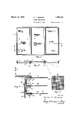
- Fig. 1 is a. front'elevational view of a filter F bank
- Fig. 2 is a sectional view on the line 2-2. of Fig. 1
- Fig. 3 is, an enlarged sectional view on the line 3-3 of Fig. 1
- Fi 4 is a plan view of a portion of one of the filter elements 5
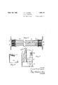
- Fig. 5 is a sectional view through a modified form of filter element
- Fig. 6 is a plan View of the element shown in Fig. 5
- The. present filter is of the dry type, that is ing height of air chamber, thenumber of course varying with the amount of air which it is necessary to handle.
- a framework 1 formed of angle irons which is secured to the building Wall, these angle irons being formed around-each 'filtersection, the angles of adjacent sections being secured together to form T-angles 2 when the units are in place.
- -Each filter unit 5 proper consists of series of spaced elements each having an angle iron frame "3. The frame of the inner.
- the filter element itself 55 being placed against the outer surface of one face of the frame 3 and being held thereagainst by means of a second angle iron frame 7 which is secured thereto by bolts 8 andnuts 9 so as to clamp the filter element 10 secure- 00 1y between the two faces of the angle iron frames 3 and 7 the other sides 11 and 12 being spaced apart.
- the outer frame 7 u being provided with a felt or similar packing strip 15 which is riveted thereto and which 65 when the filter is in position, is forced tightly against the face of the inner frame 3 to make a satisfactory air seal at the sides, top' and bottom of the frame.
- This so-called fixed frame 3 has mounted at 70' one side hinges 17 which carry the next socalled fixed frame 13 for the second filter element, the element 20 itself being secured to this angle iron frame in the same manner as is the inner element.
- the present 75 filter comprises three filter elements 10, 20
- the third or intake side element also being carried by a fixed angle iron frame 23, the element in this case being secured thereto by a frame, flat strips or a band 24 which are held against the element by bolts 8 and nuts 9.
- This third outer angle iron frame 13 and its associated element 30 are pivotally mounted by hinges 27 which are secured to the second and third fixed frames 13v and 23.
- The.element is preferably cleaned by the use of'a vacuum cleaner which is passed over the front. surface of the element, thus sucking the dirt from the element, and as the front element or intake 30 is cleaned the latch members are released and the front element swung back into the position shown in dotted sheets 64 of heavy screen with an intermedithe element on each' side of the U, a strip 6O linesin Fig. 2, at which'point the intermediate element 20 maybe subjected to the same cleaning action, and then swung outwardly as shown in Fig. 2, leaving the inner or exhaust side element 30 free so that it can be cleaned in the same manner.
- the filter is susceptible of careful and thorough cleaning, the individual elements themselves being cleaned separately, ⁇ and these elements are preferably formed of two sheets of heavy coarse meshed wire screen 41, betweenwhich is mounted a sheet of filter cloth 42, the outer screens acting as guards and'a'lso as a supporting medium for the .cloth which in itself "merely acts as a filtering medium' and does not have to take any of the force or wear from the air stream.
- Figs. 5, 6 and 7 the same-type of filter 1s shown as applied to a unit heater, these unit heaters consisting of a casing with an air inlet opening 51 at the bottom which is"controlled by a damper 52, the air thence passing up through the filter unit 54:, above which is I mounted the suction fan or blower 55, which in turn forces the air up and past the heating coil or radiator 56, and then upwardly through theexhaust opening 57 in the top of the heater casing.
- This filter inlet 60 as best illustrated in Fig. 5, consists of three individual filter elements 61, 62 and 63 of the same type as those shown in the previous construction, namely, consisting of two armoring ate sheet 65 of filter cloth.
- Each of these elements is provided with a' U-shaped frame 66, there being interposed between the frame and of felt or other sealing material which has an enlarged rib 69 adjacent the frame, these sealing strips being adapted to contact witheach other when the elements are together to form an air-tight seal around the edges of the filter unit.
- the U-strips of the three elements are hinged together as at 70 so that theelements may be opened up and cleaned with a vacuum cleaner in the same manner as for the large elements pre- 1 viously described. In this type of heater.
- filter unit is removable by sliding it into and out of a properly formed framework 72 mounted in the unit heater hbifising, this framework being preferably twosets of angle irons of sulficient depth to allow the outer 'feltstrips-to contact and engage with the angles so as to seal the unit in place in the housing. In this case the unit is merely slid ditions.
- the stationary form such as .shown in the first several figures, is easily built and handled in large units from the standpoint of erection as it provides a rigid angle iron foundation or supporting frame to which the several elements themselves may be hinged, whereas in the small or unit type of heater the filter elements are easily removable, and cleanable when removed, and new elements may be substituted if necessary.
- the individual elements themselves are readily removable and interchangeable if any element becomes damaged or needs to be replaced for any reason.
- each element is constructed with its own imeans for sealing it in place against the frame andagainst the next element so that there is no air seepage or bypassing around the elements,
- a filter of the character described comprising a series offilter elements arranged in spaced relationship superposed on one another, each of saidelements consisting of a layer'of porous non-metallic material joined to a layer of reticulated metallic material and anarro'w reinforcing frame attached to the outer edges of said layers, means adapted to hingedly attach said elements to each other; and otherresilient means adapted to seal the joint between saidelements along the edges of said frames.
- each of said laminae being hingedly attached 1 to the other in sequence, andmeans adapted to seal the periphery of each of said laminae against the other.
- An air filter consisting of a main frame,
- a second filter. element a filter element frame carrying a filter me frame. carrying a filter medium hinged to c 1,800,1oi
- said first element frame and means for lock-. ing said element frames together and to's'aid main frame.
- An air filter consisting of a mainframe, a filter element frame carrying a filter medium hinged thereto, a second filterelement frame carrying a filter medium hinged to said first element frame, and sealing means carried by said element frames for sealing them to each other and to said main frame.
- a filter of the class described consisting of a series of rectangular frames carrying filter material, said frames being hinged together and adapted to open and close in booklike manner, sealing strips mounted on the sides of certain of said frames to form airtight seals with the other of said frames in closed position.
- An air filter consisting of a frame, a I
- filter element frame carrying filter material rigidly. secured thereto, a second filter element frame carrying filter material hinged to said first frame, a sealing strip carried by said first frame andadapted to engage withsaid second frame in closed position to seal said frames, and means to lock said frames in closed position.
- An air filter consisting of a frame, a filter element frame carrying filter material rigidly secured thereto, and a plurality of other filter element frames each carrying a filter medium,said other frames being hinged to each other 'andto said first frame, a seala ing strip mounted between each two filter element frames and carried by a' frame and adapted to engage with the adjacent frame in the closedposition of said filter to form an air seal between.frames,and means for locking saidframes in closed position.
- An air' filter comprising a'stationary frame. a filter element frame hingedly attached to said stationary frame and carry-- 7 ing a filter; element removably secured thereto, said filter element consisting of two sheets of metallic foraminous material, and a sheet of non-metallic fabric interposed therebetween and in close contactual relationship therewith, and resilient means adapted to sealthe joint between said frames along the edges when in closed relation, "9.
- An air filter comprising a stationary supporting frame, a plurality of filter ele-' ment frames hinged to said supporting. frame and to each other, filter.
- hinged frame comprising a sheet of nonmetallic foraminous material secured in close contactual relation between two sheets of metallic foraminous material, resilient means cooperating with said filter element frames adapted to, seal the joints therebetween, and operative means adapted to lock said hinged frames together and to said stationary frame.
- An air filter comprising a stationary rectangular supporting ame, a plurality ofv movable rectangular framesof approximate-
Landscapes
- Chemical & Material Sciences (AREA)
- Chemical Kinetics & Catalysis (AREA)
- Filtering Of Dispersed Particles In Gases (AREA)
Description
March 22, 1932. o, v. GREENE FILTER MECHANISM 2 Sheet's-Sheet Filed May 4, 1929 INVENTOR.
ATTORNEYS.
March 22, 1932. 0, v, GREENE FILTER MECHANISM Filed May 4, 1929 2 Sheets-Sheet E INVENTOR. Oscar P. Greene ATTORNEYS.
m iag Patented Mar. 22, 1 932 i UNITED STA OSCAR GREENE, OF CLEVELAND, OHIO FILTER mncnnmsm Application filed May 4, 1929. serial No. 860,411.
To the accomplishment of the foregoing and related ends, said invention, then, con- 5 sists of the means hereinafter fully described and particularly pointed out in the claims; the annexed drawings and the following description setting. forth in detail certain ,mechanism embodying the invention, such disclosed means constituting, however, but
one. of various-mechanical forms in which the principle of the invention may be used.
In said annexed drawings: Fig. 1 is a. front'elevational view of a filter F bank; Fig. 2 is a sectional view on the line 2-2. of Fig. 1; Fig. 3 is, an enlarged sectional view on the line 3-3 of Fig. 1; Fi 4: is a plan view of a portion of one of the filter elements 5 Fig. 5 is a sectional view through a modified form of filter element; Fig. 6 is a plan View of the element shown in Fig. 5; and Fig. 7-is a sectional View through a unit heater mechanism showing the manner of installing a filter of the type shown in Figs. 5 and 6.
The. present filter is of the dry type, that is ing height of air chamber, thenumber of course varying with the amount of air which it is necessary to handle. In such a mounting there is a framework 1 formed of angle irons which is secured to the building Wall, these angle irons being formed around-each 'filtersection, the angles of adjacent sections being secured together to form T-angles 2 when the units are in place. -Each filter unit 5 proper. consists of series of spaced elements each having an angle iron frame "3. The frame of the inner. or exhaust side element is secured to the main frame 1 by means of rivets 6 or the like, the filter element itself 55 being placed against the outer surface of one face of the frame 3 and being held thereagainst by means of a second angle iron frame 7 which is secured thereto by bolts 8 andnuts 9 so as to clamp the filter element 10 secure- 00 1y between the two faces of the angle iron frames 3 and 7 the other sides 11 and 12 being spaced apart. and the outer frame 7 u being provided with a felt or similar packing strip 15 which is riveted thereto and which 65 when the filter is in position, is forced tightly against the face of the inner frame 3 to make a satisfactory air seal at the sides, top' and bottom of the frame. f
This so-called fixed frame 3 has mounted at 70' one side hinges 17 which carry the next socalled fixed frame 13 for the second filter element, the element 20 itself being secured to this angle iron frame in the same manner as is the inner element. As shown, the present 75 filter comprises three filter elements 10, 20
and spaced apart,.the third or intake side element also being carried by a fixed angle iron frame 23, the element in this case being secured thereto by a frame, flat strips or a band 24 which are held against the element by bolts 8 and nuts 9. This third outer angle iron frame 13 and its associated element 30 are pivotally mounted by hinges 27 which are secured to the second and third fixed frames 13v and 23. To lock the .elements'in their sealed position there is mounted on the main frame 1 a series of latch members 32 which are sprung over the frame members so 00 as to latch them into their sealing position, as
best'shown in Fig. 2.,"
The.element is preferably cleaned by the use of'a vacuum cleaner which is passed over the front. surface of the element, thus sucking the dirt from the element, and as the front element or intake 30 is cleaned the latch members are released and the front element swung back into the position shown in dotted sheets 64 of heavy screen with an intermedithe element on each' side of the U, a strip 6O linesin Fig. 2, at which'point the intermediate element 20 maybe subjected to the same cleaning action, and then swung outwardly as shown in Fig. 2, leaving the inner or exhaust side element 30 free so that it can be cleaned in the same manner. In this way the filter is susceptible of careful and thorough cleaning, the individual elements themselves being cleaned separately,} and these elements are preferably formed of two sheets of heavy coarse meshed wire screen 41, betweenwhich is mounted a sheet of filter cloth 42, the outer screens acting as guards and'a'lso as a supporting medium for the .cloth which in itself "merely acts as a filtering medium' and does not have to take any of the force or wear from the air stream.
' In Figs. 5, 6 and 7 the same-type of filter 1s shown as applied to a unit heater, these unit heaters consisting of a casing with an air inlet opening 51 at the bottom which is"controlled by a damper 52, the air thence passing up through the filter unit 54:, above which is I mounted the suction fan or blower 55, which in turn forces the air up and past the heating coil or radiator 56, and then upwardly through theexhaust opening 57 in the top of the heater casing. This filter inlet 60, as best illustrated in Fig. 5, consists of three individual filter elements 61, 62 and 63 of the same type as those shown in the previous construction, namely, consisting of two armoring ate sheet 65 of filter cloth. Each of these elements is provided with a' U-shaped frame 66, there being interposed between the frame and of felt or other sealing material which has an enlarged rib 69 adjacent the frame, these sealing strips being adapted to contact witheach other when the elements are together to form an air-tight seal around the edges of the filter unit. As illustrated, at one side, the U-strips of the three elements are hinged together as at 70 so that theelements may be opened up and cleaned with a vacuum cleaner in the same manner as for the large elements pre- 1 viously described. In this type of heater. the
filter unit is removable by sliding it into and out of a properly formed framework 72 mounted in the unit heater hbifising, this framework being preferably twosets of angle irons of sulficient depth to allow the outer 'feltstrips-to contact and engage with the angles so as to seal the unit in place in the housing. In this case the unit is merely slid ditions.
sary and yet provide for easy cleaning of each individual element. The stationary form, such as .shown in the first several figures, is easily built and handled in large units from the standpoint of erection as it provides a rigid angle iron foundation or supporting frame to which the several elements themselves may be hinged, whereas in the small or unit type of heater the filter elements are easily removable, and cleanable when removed, and new elements may be substituted if necessary. In the large installation type the individual elements themselves are readily removable and interchangeable if any element becomes damaged or needs to be replaced for any reason. In addition, each element is constructed with its own imeans for sealing it in place against the frame andagainst the next element so that there is no air seepage or bypassing around the elements,
and thus all of the air must pass through the filter elements in sequence.
Other modes of applying the principle of my invention may be employed instead ofthe one explained, change being made as regards the mechanism herein disclosed, provided the means stated by any of the following claims or the equivalent of such stated means be employed. I I therefore particularly point out and distinctly claim as my 1nvention:--
1. A filter of the character described comprising a series offilter elements arranged in spaced relationship superposed on one another, each of saidelements consisting of a layer'of porous non-metallic material joined to a layer of reticulated metallic material and anarro'w reinforcing frame attached to the outer edges of said layers, means adapted to hingedly attach said elements to each other; and otherresilient means adapted to seal the joint between saidelements along the edges of said frames.
2. The combination of an-air passageway and a filter obstructing said passageway, said filter comprising several laminae of filtering materialspaced in superposed relationship,
each of said laminae being hingedly attached 1 to the other in sequence, andmeans adapted to seal the periphery of each of said laminae against the other. 1
.3. An air filter consisting of a main frame,
diu'm hinged thereto, a second filter. element .a filter element frame carrying a filter me frame. carrying a filter medium hinged to c 1,800,1oi
said first element frame, and means for lock-. ing said element frames together and to's'aid main frame.
4. An air filter consisting of a mainframe, a filter element frame carrying a filter medium hinged thereto, a second filterelement frame carrying a filter medium hinged to said first element frame, and sealing means carried by said element frames for sealing them to each other and to said main frame.
5. A filter of the class described, consisting of a series of rectangular frames carrying filter material, said frames being hinged together and adapted to open and close in booklike manner, sealing strips mounted on the sides of certain of said frames to form airtight seals with the other of said frames in closed position.
6. An air filter consisting of a frame, a I
filter element frame carrying filter material rigidly. secured thereto, a second filter element frame carrying filter material hinged to said first frame, a sealing strip carried by said first frame andadapted to engage withsaid second frame in closed position to seal said frames, and means to lock said frames in closed position.
1y corresponding opening dimensions and register hinged to said stationary frame and to each other, foraminous elements mounted -7. An air filter consisting of a frame, a filter element frame carrying filter material rigidly secured thereto, and a plurality of other filter element frames each carrying a filter medium,said other frames being hinged to each other 'andto said first frame, a seala ing strip mounted between each two filter element frames and carried by a' frame and adapted to engage with the adjacent frame in the closedposition of said filter to form an air seal between.frames,and means for locking saidframes in closed position.
8.- An air' filter comprisinga'stationary frame. a filter element frame hingedly attached to said stationary frame and carry-- 7 ing a filter; element removably secured thereto, said filter element consisting of two sheets of metallic foraminous material, and a sheet of non-metallic fabric interposed therebetween and in close contactual relationship therewith, and resilient means adapted to sealthe joint between said frames along the edges when in closed relation, "9. An air filter comprising a stationary supporting frame, a plurality of filter ele-' ment frames hinged to said supporting. frame and to each other, filter. elements mounted in said hinged frame comprising a sheet of nonmetallic foraminous material secured in close contactual relation between two sheets of metallic foraminous material, resilient means cooperating with said filter element frames adapted to, seal the joints therebetween, and operative means adapted to lock said hinged frames together and to said stationary frame.
10. An air filter comprising a stationary rectangular supporting ame, a plurality ofv movable rectangular framesof approximate-
Priority Applications (1)
| Application Number | Priority Date | Filing Date | Title |
|---|---|---|---|
| US360411A US1850101A (en) | 1929-05-04 | 1929-05-04 | Filter mechanism |
Applications Claiming Priority (1)
| Application Number | Priority Date | Filing Date | Title |
|---|---|---|---|
| US360411A US1850101A (en) | 1929-05-04 | 1929-05-04 | Filter mechanism |
Publications (1)
| Publication Number | Publication Date |
|---|---|
| US1850101A true US1850101A (en) | 1932-03-22 |
Family
ID=23417849
Family Applications (1)
| Application Number | Title | Priority Date | Filing Date |
|---|---|---|---|
| US360411A Expired - Lifetime US1850101A (en) | 1929-05-04 | 1929-05-04 | Filter mechanism |
Country Status (1)
| Country | Link |
|---|---|
| US (1) | US1850101A (en) |
Cited By (7)
| Publication number | Priority date | Publication date | Assignee | Title |
|---|---|---|---|---|
| US2499949A (en) * | 1945-07-19 | 1950-03-07 | Air Maze Corp | Filter panel |
| US2583881A (en) * | 1946-03-30 | 1952-01-29 | Rasmussen James William | Dust collector |
| US2928496A (en) * | 1956-11-30 | 1960-03-15 | Mine Safety Appliances Co | Combined separator and baffle |
| DE2343327A1 (en) * | 1972-09-11 | 1974-03-21 | Cigarette Components Ltd | FILTERS, IN PARTICULAR TOBACCO SMOKE FILTERS |
| US5679121A (en) * | 1994-12-10 | 1997-10-21 | Samsung Electronics Co., Ltd. | Air filter attachment apparatus of air conditioner |
| US20070199289A1 (en) * | 2006-02-03 | 2007-08-30 | Bland Larry E Jr | Filter Holding Frame with Clamping Mechanism |
| US20210276401A1 (en) * | 2018-07-06 | 2021-09-09 | Dyson Technology Limited | Vehicle cabin filter assembly |
-
1929
- 1929-05-04 US US360411A patent/US1850101A/en not_active Expired - Lifetime
Cited By (9)
| Publication number | Priority date | Publication date | Assignee | Title |
|---|---|---|---|---|
| US2499949A (en) * | 1945-07-19 | 1950-03-07 | Air Maze Corp | Filter panel |
| US2583881A (en) * | 1946-03-30 | 1952-01-29 | Rasmussen James William | Dust collector |
| US2928496A (en) * | 1956-11-30 | 1960-03-15 | Mine Safety Appliances Co | Combined separator and baffle |
| DE2343327A1 (en) * | 1972-09-11 | 1974-03-21 | Cigarette Components Ltd | FILTERS, IN PARTICULAR TOBACCO SMOKE FILTERS |
| US5679121A (en) * | 1994-12-10 | 1997-10-21 | Samsung Electronics Co., Ltd. | Air filter attachment apparatus of air conditioner |
| US20070199289A1 (en) * | 2006-02-03 | 2007-08-30 | Bland Larry E Jr | Filter Holding Frame with Clamping Mechanism |
| US8062402B2 (en) * | 2006-02-03 | 2011-11-22 | Camfil Farr, Inc. | Filter holding frame with clamping mechanism |
| US20210276401A1 (en) * | 2018-07-06 | 2021-09-09 | Dyson Technology Limited | Vehicle cabin filter assembly |
| US12257883B2 (en) * | 2018-07-06 | 2025-03-25 | Dyson Technology Limited | Vehicle cabin filter assembly |
Similar Documents
| Publication | Publication Date | Title |
|---|---|---|
| US1850101A (en) | Filter mechanism | |
| US2980208A (en) | Filter element for extremely fine dust | |
| US2864462A (en) | Disposable filter bag for suction cleaners | |
| US2907408A (en) | Filter construction | |
| US3273321A (en) | Air filter having a replaceable cartridge | |
| US6997966B2 (en) | Lint trap | |
| US1883715A (en) | Armored filter element | |
| US3487624A (en) | Lint catcher | |
| US2080154A (en) | Air filter | |
| US2359289A (en) | Shutter | |
| US2020120A (en) | Vacuum cleaner filter | |
| US2754747A (en) | Air register or louver | |
| US1830096A (en) | Panel air filter | |
| US1081195A (en) | Window-ventilator. | |
| US4045931A (en) | Insulating flexible composite element | |
| US3606739A (en) | Air filter | |
| US1049789A (en) | Filter. | |
| US2050508A (en) | Gas filter | |
| US1938798A (en) | Silencing ventilator for windows | |
| US2693246A (en) | Air filter | |
| US3410060A (en) | Xerographic filter apparatus | |
| CS203110B2 (en) | Frash air pass for room aerotion | |
| US1566088A (en) | Dust-cleaning element | |
| US2082481A (en) | Air filter for ventilating systems or apparatus | |
| US1814428A (en) | Air filter |