US1850008A - Fire extinguishing device - Google Patents
Fire extinguishing device Download PDFInfo
- Publication number
- US1850008A US1850008A US506231A US50623131A US1850008A US 1850008 A US1850008 A US 1850008A US 506231 A US506231 A US 506231A US 50623131 A US50623131 A US 50623131A US 1850008 A US1850008 A US 1850008A
- Authority
- US
- United States
- Prior art keywords
- tube
- nozzle
- fire extinguishing
- outlet
- closure
- Prior art date
- Legal status (The legal status is an assumption and is not a legal conclusion. Google has not performed a legal analysis and makes no representation as to the accuracy of the status listed.)
- Expired - Lifetime
Links
- 238000005507 spraying Methods 0.000 description 11
- 239000007788 liquid Substances 0.000 description 10
- 239000000725 suspension Substances 0.000 description 10
- 230000003313 weakening effect Effects 0.000 description 7
- 238000005452 bending Methods 0.000 description 6
- 238000010276 construction Methods 0.000 description 2
- 238000005096 rolling process Methods 0.000 description 2
- 239000002253 acid Substances 0.000 description 1
- 230000015572 biosynthetic process Effects 0.000 description 1
- 238000005260 corrosion Methods 0.000 description 1
- 230000007797 corrosion Effects 0.000 description 1
- 238000004519 manufacturing process Methods 0.000 description 1
- 239000000463 material Substances 0.000 description 1
- 239000002184 metal Substances 0.000 description 1
- 238000000034 method Methods 0.000 description 1
- 238000003825 pressing Methods 0.000 description 1
- 230000002035 prolonged effect Effects 0.000 description 1
- 239000007921 spray Substances 0.000 description 1
- 239000000126 substance Substances 0.000 description 1
- XLYOFNOQVPJJNP-UHFFFAOYSA-N water Substances O XLYOFNOQVPJJNP-UHFFFAOYSA-N 0.000 description 1
Images
Classifications
-
- A—HUMAN NECESSITIES
- A62—LIFE-SAVING; FIRE-FIGHTING
- A62C—FIRE-FIGHTING
- A62C13/00—Portable extinguishers which are permanently pressurised or pressurised immediately before use
- A62C13/003—Extinguishers with spraying and projection of extinguishing agents by pressurised gas
Definitions
- This invention relates to fire extinguishing devices, more particularly to those of the portable type and in which a special fire extinguishing liquid other than water is employed.
- the invention has foran object to provide a portable fire extinguishing device which is of a simple and light construction, lending itself readily to formation from non-corrodible material such as lead and to being sealed 0 hermetically, and which whilst very inexpen sive shall be capable of containing an adequate supply of fire extinguishing liquid, and thoroughly effective in use.
- a fire extinguishing device comprises essentially a so-called collapsible tube having an outlet in the form of a spraying nozzle; the invention also providing a method of obtaining a jet of fire extinguishing liquid from a so-called collapsible tube, which consists in enclosing a quantity of such liquid, together with a quantity of gaseous medium, in such a tube and applying pressure to the latter to compress the gaseous medium.
- a continuous jet of liquid may be produced even though pressure be applied intermittently to the tube.
- the outlet spraying nozzle thereof may extend for some distance within the confines of the tube.
- means may e provided whereby it may readily be collapsed; for example, by rolling the tube upon itself from its closed end.
- a handle secured pivotally to the latter substantially about an axis in a plane substantially parallel with the axis of the tube, said handle lying normally across the closed end of the tube, and, when required for use, being moved about its pivot and rotated about an axis substantially at right angles to that of said pivot.
- Such a handle may conveniently be secured to the tube by means of the clip whereby one end thereof is as a rule closed, the handle proper being of substantially L shape.
- the outlet spraying nozzle of the tube may be closed in any known or convenient manby pulling the tube without first freeing such ner, as by an ordinary screw cap, but it is desirable that suspension means should be attached to the tube outlet in such manner that the opening of the outlet may be effected suspension means from a hook from which the whole is suspended.
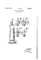
- Figure 1 is a part sectional side view of a tube from which the closure is omitted
- Figures 2, 3, 4 and 5 are fragmentary views showing in section alternative arrangements at the outer end of the spraying nozzle.
- a collapsible tube 11 is enclosed at its lower end by means of a clip 12, which is of usual type, except that it is extended at 13- at one end to embrace one limb 14 of an L shaped handle 15, which normally occupies a position in which its longer limb 16 lies parallel with said clip 12 and to permit said handle to be rocked through substantially to extend at right angles to the tube axis at one side of the tube.
- the handle 15 By then rotating the handle 15 about an axis at right angles to the limb 14 thereof, the tube may very readily be collapsed by rolling it up about the clip 12 from its lower end.
- an outlet in the form of a spraying nozzle 17 extends for a short distanceas shown at lS-Within the confines of the tube to trap a'quantity of gaseous medi- -um which, together with a quantity of fire extinguishing liquid, is contained within the tube.
- the walls thereof are preferably weakened circumferent-ially as indicated at 20.
- the upper end of the nozzle 17 may be closed in any desired manner, as by a screw cap or stopper of ordinary type,'but preferably an arrangement such as those shownin Figures 2, 3, 4 and 5' of the drawings is provided.
- the suspension means 24 extend from the lug 22 at 23, through an aperture 28 formed in an upward extension29 of a closure 30 at the upper end of the nozzle 17.
- the closure 30 extends vertically from the'nozzle before the tube is filled through the latter,
- the upward extension 29 of the closure 30 is weak so that it will fracture when the tube is pulled downwardly, enabling the suspension means to exert a bending moment upon the nozzle and thus causethe latter to break ofl at the weakening 20 thereof.
- FIG. 4 The arrangement of Figure 4 is similar, except that in this case the closure for the nozzle is comprised by a stopper or plug 34, which may or may not be soldered in position.
- the suspension means 24 extend through an aperture 32in a weakened upward extension 33 of the plug 34, which extension 33 is adapted to-fracture easily as in the previous case.
- the upward I extensions 26, 29 and 33 are provided in order that normally the tube may be suspended in a substantially vertical position.
- a fire extinguishing device is particularly advantageous in that it may be employed with fire extinguishing liquids of a highly corrosive nature, that it may without difficulty be sealed hermetically, and that it contains no mechanism of any sort.
- the present invention enables the provision very inexpensively of a simple and reliable fire extinguishing device, which will be thoroughly effective in use, even when left for a prolonged period, and which is of a practically foolproof nature.
- a collapsible tube having an outlet in the form of a spraying nozzle which extends for some distance within the confines of the tube to trap gaseous medium in the tube during the ejection of liquid therefrom, means whereby the tube may readily be collapsed for the purpose of ejecting its contents through said outlet, said outlet being closed and provided with suspending means at its outer end, whilst near said outer end it is weakened circumferentially.
- a collapsible tube for use as a portable fireextinguishing device, an outlet in the form of a spraying .noz'zle closed at, and weakened circumferentially near, its outer end, a lateral extension from thenozzle at that side of the circumferential weakening remote from its inner end, and suspension means attached to said lateral extension at a point remote from" the' axis of the tube to impart-a bending moment to the nozzle when the suspended tube is pulled.
- a portable fire extinguisher comprising a collapsible .tube having an outlet in the form of a spraying nozzle and weakened circumferen-tially near the outer end, a closure for the outlet, a lateral extension above the weakened portion, a hanger pivoted near the outer end of the extension and extending over the axis of the tube and formed with an end to suspend the tube in a vertical position, a readily breakable guide extending from the lateral extension adjacent the tube and through which the hanger extends, whereby when the tube is pulled vertically the guide breaks and a bending strain is imparted to the nozzle and the outer end portion breaks at the circumferential weakened portion to release the contents of the tube.
Landscapes
- Health & Medical Sciences (AREA)
- Public Health (AREA)
- Business, Economics & Management (AREA)
- Emergency Management (AREA)
- Containers And Packaging Bodies Having A Special Means To Remove Contents (AREA)
Description
Mrch 15-, 1932. I
fins sx'rmdursuruo nuv'rca Fil d Jan; 2, 19am Yuri/v70 Rf: GO/PA' Patented Mar. 15, 1932 UNITED STATES PATENT OFFICE- REGINALD EDWARD GORE, OF LONDON, ENGLAND FIRE EXTINGUISHING DEVICE Application filed January 2,1931, Serial No. 506,231 and in Great Britain September 30, 1930.
This invention relates to fire extinguishing devices, more particularly to those of the portable type and in which a special fire extinguishing liquid other than water is employed.
The invention has foran object to provide a portable fire extinguishing device which is of a simple and light construction, lending itself readily to formation from non-corrodible material such as lead and to being sealed 0 hermetically, and which whilst very inexpen sive shall be capable of containing an adequate supply of fire extinguishing liquid, and thoroughly effective in use.
A fire extinguishing device according to the invention comprises essentially a so-called collapsible tube having an outlet in the form of a spraying nozzle; the invention also providing a method of obtaining a jet of fire extinguishing liquid from a so-called collapsible tube, which consists in enclosing a quantity of such liquid, together with a quantity of gaseous medium, in such a tube and applying pressure to the latter to compress the gaseous medium. By such an arrangement, a continuous jet of liquid may be produced even though pressure be applied intermittently to the tube. In order to ensure the trapping of gaseous medium within the tube, the outlet spraying nozzle thereof may extend for some distance within the confines of the tube.
For sim lifying the use of the device, means may e provided whereby it may readily be collapsed; for example, by rolling the tube upon itself from its closed end. For this purpose there may be provided at the closed end of the tube a handle secured pivotally to the latter substantially about an axis in a plane substantially parallel with the axis of the tube, said handle lying normally across the closed end of the tube, and, when required for use, being moved about its pivot and rotated about an axis substantially at right angles to that of said pivot. Such a handle may conveniently be secured to the tube by means of the clip whereby one end thereof is as a rule closed, the handle proper being of substantially L shape.
The outlet spraying nozzle of the tube may be closed in any known or convenient manby pulling the tube without first freeing such ner, as by an ordinary screw cap, but it is desirable that suspension means should be attached to the tube outlet in such manner that the opening of the outlet may be effected suspension means from a hook from which the whole is suspended.
The invention is illustrated by the accompanying drawings, of which Figure 1 is a part sectional side view of a tube from which the closure is omitted, whilst Figures 2, 3, 4 and 5 are fragmentary views showing in section alternative arrangements at the outer end of the spraying nozzle.
As shown in Figure 1, a collapsible tube 11 is enclosed at its lower end by means of a clip 12, which is of usual type, except that it is extended at 13- at one end to embrace one limb 14 of an L shaped handle 15, which normally occupies a position in which its longer limb 16 lies parallel with said clip 12 and to permit said handle to be rocked through substantially to extend at right angles to the tube axis at one side of the tube. By then rotating the handle 15 about an axis at right angles to the limb 14 thereof, the tube may very readily be collapsed by rolling it up about the clip 12 from its lower end.
At the upper end of the tube, which is shown in section, an outlet in the form of a spraying nozzle 17 extends for a short distanceas shown at lS-Within the confines of the tube to trap a'quantity of gaseous medi- -um which, together with a quantity of fire extinguishing liquid, is contained within the tube. Just above the outlet orifice 19 of the nozzle 17 the walls thereof are preferably weakened circumferent-ially as indicated at 20. The upper end of the nozzle 17 may be closed in any desired manner, as by a screw cap or stopper of ordinary type,'but preferably an arrangement such as those shownin Figures 2, 3, 4 and 5' of the drawings is provided.
In the arrangement shown in Figure 2, the upper end of the nozzle 17 is closed as shown at 21, whilst from the nozzle between said end 21 and the weakening 20 there extends laterally a lug 22 to which is pivotally attached at 23 a wire suspension member 24,
tively weak upward extension' 25 from the lug 22 and terminates in a ring 26 coaxial with the-tube whereby the latter may be suspended from a hook or nail. With this arrangement the tube may be readily suspended in a vertical position, and a downward pull upon the suspended tube will result, first, in a fracture of the extension 25, and, secondly, a pull at the end 23 upon the lug 22. This latter pull will result in a bending moment upon the nozzle itself which will, if-the pull be strong enough, break at the weakening 20, leaving the outlet orifice 19 of the nozzle 17-free for emission of fireex'tinguishing liquid.
In the arrangement shown in Figure 3, the suspension means 24 extend from the lug 22 at 23, through an aperture 28 formed in an upward extension29 of a closure 30 at the upper end of the nozzle 17. In this case the closure 30 extends vertically from the'nozzle before the tube is filled through the latter,
and after filling the closure 30 is bent down into position and soldered to the nozzle so as to provide a hermetic seal.
As in the arrangement of Figure 2, the upward extension 29 of the closure 30 is weak so that it will fracture when the tube is pulled downwardly, enabling the suspension means to exert a bending moment upon the nozzle and thus causethe latter to break ofl at the weakening 20 thereof.
The arrangement of Figure 4 is similar, except that in this case the closure for the nozzle is comprised by a stopper or plug 34, which may or may not be soldered in position. Here again, the suspension means 24 extend through an aperture 32in a weakened upward extension 33 of the plug 34, which extension 33 is adapted to-fracture easily as in the previous case.
In all these three arrangements the upward I extensions 26, 29 and 33 are provided in order that normally the tube may be suspended in a substantially vertical position.
The arrangement shown in Figure 5 differs from the previous arrangements in that there is no wea ening of the nozzle 17 and in that the upper end thereof is closed by a-cap 35, from the centre of which there extends upwardly suspension means terminating in a ring 36. It will be observed that a pull upon the suspended tube will result in the complete removal of the closure 35.
In all cases the tube and associated parts, with the possible exception of the suspension means 24 or 36,the clip 12 and handle 15,
are formed from metal, such as lead, which is not subject to corrosion by chemicals. In view of the simple construction of the device, this may be accomplished without difficulty, enabling the device to be used for the application of fire extinguishing liquids of a highly corrosive nature, whether acid or a ejection of air or other gaseous medium enclosed within the tube until the latter is practically empty, even though the device be used for the production of a jet or spray in an upwarddirection.
A fire extinguishing device according to theinvention is particularly advantageous in that it may be employed with fire extinguishing liquids of a highly corrosive nature, that it may without difficulty be sealed hermetically, and that it contains no mechanism of any sort.
It will also be observed that the present invention enables the provision very inexpensively of a simple and reliable fire extinguishing device, which will be thoroughly effective in use, even when left for a prolonged period, and which is of a practically foolproof nature.
What I claim is 1. For use as a portable fire extinguishing device, a collapsible tube having an outlet in the form of a spraying nozzle which extends for some distance within the confines of the tube to trap gaseous medium in the tube during the ejection of liquid therefrom, means whereby the tube may readily be collapsed for the purpose of ejecting its contents through said outlet, said outlet being closed and provided with suspending means at its outer end, whilst near said outer end it is weakened circumferentially.
2. In a collapsible tube for use as a portable fire extinguishing device, an outlet in the form of a spraying nozzle closed at, and weakened circumferentially near, its outer end, andsuspension means pivotally attached strongly to the nozzle at that side of the circumferential weakening remote from its inner end and to one side of the axis of the tube, extending from said pivotal attachment to the axis of the tube, and being attached weakly to the closed end of the nozzle to s1lspend the tube in a substantially vertical pothe form of a spraying nozzle weakened cir-- cumferentially near its outer end, a closure device at the outer'end of the nozzle, and suspension means attached to the nozzle at that side of the circumferential weakening remate from its inner end and to one side of the axis of the tube, extending from said pivotal attachment to the axis of the tube, and being attached weakly to the closure device to suspend the tube in a substantially Vertical position, and upon breakage of the closure attachment when the suspended tube is pulled to impart a bending moment to the nozzle to break off the outer end portion of the latter at the circumferential weakening.
4:. In a collapsible tube for use as a portable fireextinguishing device, an outlet in the form of a spraying .noz'zle closed at, and weakened circumferentially near, its outer end, a lateral extension from thenozzle at that side of the circumferential weakening remote from its inner end, and suspension means attached to said lateral extension at a point remote from" the' axis of the tube to impart-a bending moment to the nozzle when the suspended tube is pulled.
5. A portable fire extinguisher comprising a collapsible .tube having an outlet in the form of a spraying nozzle and weakened circumferen-tially near the outer end, a closure for the outlet, a lateral extension above the weakened portion, a hanger pivoted near the outer end of the extension and extending over the axis of the tube and formed with an end to suspend the tube in a vertical position, a readily breakable guide extending from the lateral extension adjacent the tube and through which the hanger extends, whereby when the tube is pulled vertically the guide breaks and a bending strain is imparted to the nozzle and the outer end portion breaks at the circumferential weakened portion to release the contents of the tube.
6. A portable fire extinguisher'comprising a collapsible tube having an outlet in the form of a spraying nozzle and weakened circumferentially near the outer end, a closure for the outlet, a readily breakable guide extending from the closure, a lateral extension above the weakened portion, a hanger pivoted near the outer end of the extension and extending through the readily breakable guide and formed with an end to suspend the tube, whereby when the tube is pulled vertically the guide breaks and a bending strain is imparted to the nozzle and the outer end portion reaks at the circumferential weakened portion to release the contents of the tube.
REGINALD EDWARD GORE.
Applications Claiming Priority (1)
| Application Number | Priority Date | Filing Date | Title |
|---|---|---|---|
| GB1850008X | 1930-09-30 |
Publications (1)
| Publication Number | Publication Date |
|---|---|
| US1850008A true US1850008A (en) | 1932-03-15 |
Family
ID=10891929
Family Applications (1)
| Application Number | Title | Priority Date | Filing Date |
|---|---|---|---|
| US506231A Expired - Lifetime US1850008A (en) | 1930-09-30 | 1931-01-02 | Fire extinguishing device |
Country Status (1)
| Country | Link |
|---|---|
| US (1) | US1850008A (en) |
Cited By (6)
| Publication number | Priority date | Publication date | Assignee | Title |
|---|---|---|---|---|
| US2612224A (en) * | 1948-02-21 | 1952-09-30 | Essex Products Inc | Fire extinguisher |
| US2659443A (en) * | 1950-02-17 | 1953-11-17 | Essex Products Inc | Fire extinguisher structure |
| US2759547A (en) * | 1951-09-24 | 1956-08-21 | Essex Products Inc | Fluid dispensing package and container therefor |
| US3362586A (en) * | 1965-09-02 | 1968-01-09 | Arnold A. Dedoes | Barbecue fan and fire quenching accessory |
| US3788549A (en) * | 1972-12-15 | 1974-01-29 | Federal Tool & Plastics | Plastic dispensing nozzle with pouring spout with removable seal |
| US5014879A (en) * | 1984-08-06 | 1991-05-14 | Robert Hill | Lockable tube roller |
-
1931
- 1931-01-02 US US506231A patent/US1850008A/en not_active Expired - Lifetime
Cited By (6)
| Publication number | Priority date | Publication date | Assignee | Title |
|---|---|---|---|---|
| US2612224A (en) * | 1948-02-21 | 1952-09-30 | Essex Products Inc | Fire extinguisher |
| US2659443A (en) * | 1950-02-17 | 1953-11-17 | Essex Products Inc | Fire extinguisher structure |
| US2759547A (en) * | 1951-09-24 | 1956-08-21 | Essex Products Inc | Fluid dispensing package and container therefor |
| US3362586A (en) * | 1965-09-02 | 1968-01-09 | Arnold A. Dedoes | Barbecue fan and fire quenching accessory |
| US3788549A (en) * | 1972-12-15 | 1974-01-29 | Federal Tool & Plastics | Plastic dispensing nozzle with pouring spout with removable seal |
| US5014879A (en) * | 1984-08-06 | 1991-05-14 | Robert Hill | Lockable tube roller |
Similar Documents
| Publication | Publication Date | Title |
|---|---|---|
| US2908446A (en) | Spray tube | |
| US2115959A (en) | Combined dropper and atomizer | |
| US1850008A (en) | Fire extinguishing device | |
| US2681252A (en) | Spray device | |
| US2631757A (en) | Dispensing device | |
| US2632585A (en) | Liquid spraying valve structure | |
| US1873817A (en) | Sprayer | |
| US1888174A (en) | Dispensing device for collapsible tubes | |
| US2328345A (en) | Fire-extinguishing apparatus | |
| US1848846A (en) | Measttsing device fob paste tubes | |
| US1832570A (en) | Spray device | |
| US1732282A (en) | Container for liquids | |
| US2378426A (en) | Fire extinguisher means | |
| US2547954A (en) | Apparatus for discharging liquid by a medium stored under pressure | |
| US1632218A (en) | Sprayer | |
| US1740287A (en) | Collapsible tube | |
| US2275185A (en) | Lubricating device and spray gun | |
| US1638729A (en) | Dry fire extinguisher | |
| US2628130A (en) | Spraying device | |
| US1617545A (en) | Atomizer | |
| US1790995A (en) | Itbe extinguishes | |
| US1931411A (en) | Fire extinguisher | |
| US1845698A (en) | Bottle stopper | |
| US2501279A (en) | Means for spraying or projecting powder | |
| US2187980A (en) | Fire extinguisher |