US1850004A - Vehicle spring suspension - Google Patents
Vehicle spring suspension Download PDFInfo
- Publication number
- US1850004A US1850004A US473166A US47316630A US1850004A US 1850004 A US1850004 A US 1850004A US 473166 A US473166 A US 473166A US 47316630 A US47316630 A US 47316630A US 1850004 A US1850004 A US 1850004A
- Authority
- US
- United States
- Prior art keywords
- axle
- spring
- spring suspension
- frame
- springs
- Prior art date
- Legal status (The legal status is an assumption and is not a legal conclusion. Google has not performed a legal analysis and makes no representation as to the accuracy of the status listed.)
- Expired - Lifetime
Links
- 239000000725 suspension Substances 0.000 title description 9
- 230000035939 shock Effects 0.000 description 13
- 239000006096 absorbing agent Substances 0.000 description 12
- 238000010276 construction Methods 0.000 description 5
- 241000269800 Percidae Species 0.000 description 1
- 238000010521 absorption reaction Methods 0.000 description 1
- 238000005452 bending Methods 0.000 description 1
- 230000008030 elimination Effects 0.000 description 1
- 238000003379 elimination reaction Methods 0.000 description 1
- 238000005242 forging Methods 0.000 description 1
- 238000004519 manufacturing process Methods 0.000 description 1
- 230000003068 static effect Effects 0.000 description 1
Images
Classifications
-
- B—PERFORMING OPERATIONS; TRANSPORTING
- B60—VEHICLES IN GENERAL
- B60G—VEHICLE SUSPENSION ARRANGEMENTS
- B60G11/00—Resilient suspensions characterised by arrangement, location or kind of springs
- B60G11/32—Resilient suspensions characterised by arrangement, location or kind of springs having springs of different kinds
- B60G11/34—Resilient suspensions characterised by arrangement, location or kind of springs having springs of different kinds including leaf springs
- B60G11/38—Resilient suspensions characterised by arrangement, location or kind of springs having springs of different kinds including leaf springs and also rubber springs
- B60G11/42—Resilient suspensions characterised by arrangement, location or kind of springs having springs of different kinds including leaf springs and also rubber springs the rubber springs being attached to sprung part of the vehicle
-
- B—PERFORMING OPERATIONS; TRANSPORTING
- B60—VEHICLES IN GENERAL
- B60G—VEHICLE SUSPENSION ARRANGEMENTS
- B60G11/00—Resilient suspensions characterised by arrangement, location or kind of springs
- B60G11/02—Resilient suspensions characterised by arrangement, location or kind of springs having leaf springs only
- B60G11/08—Resilient suspensions characterised by arrangement, location or kind of springs having leaf springs only arranged substantially transverse to the longitudinal axis of the vehicle
Definitions
- the object of my invention is to provide an automobile spring suspension of simple, durable, and inexpensive construction.
- a further object of my invention is to provide a spring suspension which is particularly adapted for use in supporting the front end of an automobile which sprlng sus ension will give either reater fiexibilityun -er vertical impact loa s or will increase the lateral w stability of the car.
- sprlng sus ension will give either reater fiexibilityun -er vertical impact loa s or will increase the lateral w stability of the car.
- My improved spring suspension is of the transverse type and is particularly adapted for use in connection with a tubular axle.
- Still a further object of my invention is to provide a novel hydraulic shock absorber mounting wherein the ball joint connections ordinarily provided between the shock absorber arms and the vehicle frame are eliminated and simple clevis connections substituted:
- my invention consists in the arrangement, con struction and combination of the various parts of my improved device, as described in-the provide a connection superior to the ball type specification, claimed in my claims, and illustrated in the accompanying drawings, in which:
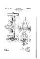
- Fi re 1 shows a front elevation of an automo ile chassis having my improved spring suspension installed thereon.
- Figure 2 shows a plan view of the front portion of the chassis shown in Figure l
- Figure 3 shows a view of my improved shock absorber mounting, part of the front axle being broken away to better illustrate the construction.
- lteferrin to the accompanying drawings, 1 have use the reference numeral to indicate the side members of an automobile frame having a front cross member 1]. disposed therebetween and reinforced by a pair of usset plates 12. lhe rear end of a motor 13 is mounted in the forward ortion of the chassis between the side mem er 10, while the forward end of this motor is secured to the center portion of a channel member 14 which extends transversely beneath the cross memberll. A pair of rubber cushions 15 are interposed between the gusset plates 12 and the ends of this channel member so that the forward end of the motor is insulated from the frame. A pairof quarter elliptic springs 16 are secured inthe outer ends of the channel 14: by U bolts 17 and extend outwardly to form a type of transverse spring. lit will be noted that the road shock must be trans mitted through both the springs 16 and cushions 15 to affect the frame of this car.
- a pair of front wheels 21 are rotatably mounted on the knuckle joints 20 in the conca ventional manner, each of these wheels being provided with a brake drum 22.
- a brake anchor plate 23 is fixedly secured to each knuckle joint 20 and upon these plates internal expanding brake shoes are mounted to tilt 1 operably engage the brake drums 22.
- each king pin 19 is provided with an eye 24 to which a spring shackle 25 is pivotally secured.
- the lower end of each spring s ackle 25 is pivotally secured to the outer end of the respective spring 16 so that the impact loads of the vehicle are transmitted from the wheels to the car without being transferred through the axle 18. No bending strains are thereby induced in the axle from impact loads.
- a pair of tubular radius rods 26 are fastened to the axle 18 at points spaced from the ends thereof and extend rearwardly where they are pivotally secured to the under side of the engine unit. The front axle is thereby supported against longitudinal movement in the conventional manner by these radius rods.
- each spring 16 extends from one of the frame side members outwardly to practically the end of the axle. For this reason greater lateral stability is obtained with this structure than is possible to v obtain with the ordinary transverse spring or with longitudinal springs.
- a novel feature in connection with my im proved device arises because the mechanism for operating the front wheel brakes is housed entirely within the axle 18 and radius rods 26 so that no exposed rods or the like need be used.
- the axle 18 is provided with a pair of enlarged portions 27 adjacent to the radius rod connections.
- the detailed description of the mechanism for operating my brakes will not be given here as it is believed suflicient to state that an operating rod 30 extends .through each of the radius rods 26- into the enlarged portion 27 of the axle 18 where each rod is secured to a bell crank lever 28 within these portions.
- Push rods 29 extend out through the lower portion of the axle from the free arms of the bell crank levers 28 so that drawing the rods 30 will pivot the bell crank levers 28 thereby pushing the rods 29 outwardly.
- the lower end of each king pin 19 is provided with an outwardly and downwardly inclined track 31 against which the outer end of one pu h rod 29 operates to therebv force these ends of the push rods downwardly when their inner ends are forced outwardly.
- a brake operating wedge 32 is actuated by the outer end of each push rod 29 so that when the device is operated the wedge 32 is pushed downwardly to thereby apply the brakes.
- the radius rods 26 form the enclosures for the rear face of the enlarged portions 27.
- novel shock absorber mountings which enclose the front faces of these enlarged portions to complete the enclosures for the bell cranks 28.
- Rotary type hydraulic shock absorbers 33 are each provided with a pair of studs 34 which extend rearwardly therefrom through the enlarged portions 2-7 of the axle and through the forward ends. of the radius rods. The shock absorbers, axle and radius rods are thereby secured together by these studs 34 so that an enclosure is formed which houses the brake operating mechanism.
- a pair of arms 35 for operating the shock absorbers extend inwardly substantially parallel to the axle 18 and links 36 are pivotally connected to their free ends and extend upwardly where they are pivotally secured to clamping plates 37, the plates being held in place by the U bolts 17
- Only simple clevis connections are required between the ends of the links 36 and the arms 35 and plates 37 for the reason qzhat these arms oscillate in the same plane in which the springs 16 Hex.
- The, elimination of the conventional ball joints for connecting up the shock absorbers materially lessens the cost of this structure and further, forms a superior connection between the chassis frame and the shock absorber.
- my novel shock absorber mounting provides an enclosure for the brake operating mechanism thereby eliminating the otherwise necessary parts required to form this enclosure.
- These shock absorbers being mounted so that their operating arms swing in a plane parallel to the plane in which the adjacent springs flex makes it unnecessary to provide ball joints for connecting these operating arms with the chassis frame.
- shock absorber mounting is thereby materially reduced and a superior connection provided.
- a chassis frame In a vehicle spring suspension, a chassis frame. a spring retaining member disposed beneath the front end of said frame, resilient cushions disposed between said retaining member and saidframe, a front axle. substantially vertical king pins secured in the ends of said axle. and quarter elliptic springs extending between the ends of said retaining member and king pins to support the chassis frame.
- a chassis eencoe frame a transverse spring retaining member disposed beneath the front end of said frame, resilient cushions disposed Mtween the ends of said retaining member and said frame, en
Landscapes
- Engineering & Computer Science (AREA)
- Mechanical Engineering (AREA)
- Vehicle Body Suspensions (AREA)
Description
March 15, 1932. E. J. FARKAs 1,350,004
VEHICLE SPRING SUSPENSION File'd, Aug. 5, 1950 INVENTOR.
M'tness. i Q flaws? A TTORNE Y.
ill
Patented Mar. 15, 1932 i um'raof STATES PATENT orrica EUGENE .17. FARKAS, F DE'IRQZlT, MICHIGAN, ASSIGNOR '1'0 FORD MOTOR comm, 0F DEABCBORN, WCHIGAN, A COMOMTION OF DELAWARE macan srnrne susr nnsrorr a lication an August a rest. serial in. states.
The object of my invention is to provide an automobile spring suspension of simple, durable, and inexpensive construction.
' A further object of my invention is to provide a spring suspension which is particularly adapted for use in supporting the front end of an automobile which sprlng sus ension will give either reater fiexibilityun -er vertical impact loa s or will increase the lateral w stability of the car. In other words, when a suflicient number of spring leaves are provided to give a predetermined resiliency or absorption of impact loads greater lateral stability will result than would be obtained with v w the equivalent resiliency incorporated in the conventional type of springs.
My improved spring suspension is of the transverse type and is particularly adapted for use in connection with a tubular axle.
as No bosses, spring mrches or the like are required tobe formed on the axle'for connecting the spring thereto so that a tubular axle may be conveniently used. I accomplish this desirable feature by forging the upper as end of each king pin to form spring perches to which the outer ends of the springs are fastened. The static and impact loads on the car are transmitted from the wheels directly through the king pins to the car springs theresa by relieving the front. axle of these loads.
For the reason that only the torsional braking loads of the wheels must be absorbed through the front axle, it may be made considerably lighter and still maintain the same factor of safety to thereby lessen the unsprung weight of the car.
Still a further object of my invention is to provide a novel hydraulic shock absorber mounting wherein the ball joint connections ordinarily provided between the shock absorber arms and the vehicle frame are eliminated and simple clevis connections substituted:
therefor. These clev'fs connections are not only much cheaper to manufacture but also connection. a
With these and other objects in view my invention consists in the arrangement, con struction and combination of the various parts of my improved device, as described in-the provide a connection superior to the ball type specification, claimed in my claims, and illustrated in the accompanying drawings, in which:
Fi re 1 shows a front elevation of an automo ile chassis having my improved spring suspension installed thereon.
Figure 2 shows a plan view of the front portion of the chassis shown in Figure l, and
Figure 3 shows a view of my improved shock absorber mounting, part of the front axle being broken away to better illustrate the construction.
lteferrin to the accompanying drawings, 1 have use the reference numeral to indicate the side members of an automobile frame having a front cross member 1]. disposed therebetween and reinforced by a pair of usset plates 12. lhe rear end of a motor 13 is mounted in the forward ortion of the chassis between the side mem er 10, while the forward end of this motor is secured to the center portion of a channel member 14 which extends transversely beneath the cross memberll. A pair of rubber cushions 15 are interposed between the gusset plates 12 and the ends of this channel member so that the forward end of the motor is insulated from the frame. A pairof quarter elliptic springs 16 are secured inthe outer ends of the channel 14: by U bolts 17 and extend outwardly to form a type of transverse spring. lit will be noted that the road shock must be trans mitted through both the springs 16 and cushions 15 to affect the frame of this car.
I have provided a tubular front axle 18 having a pair of substantially vertical king pins 19 disposed in each end thereof upon which knuckle joints 20 are swivelly mounted A pair of front wheels 21 are rotatably mounted on the knuckle joints 20 in the conca ventional manner, each of these wheels being provided with a brake drum 22. A brake anchor plate 23 is fixedly secured to each knuckle joint 20 and upon these plates internal expanding brake shoes are mounted to tilt 1 operably engage the brake drums 22.
The upper end of each king pin 19 is provided with an eye 24 to which a spring shackle 25 is pivotally secured. The lower end of each spring s ackle 25 is pivotally secured to the outer end of the respective spring 16 so that the impact loads of the vehicle are transmitted from the wheels to the car without being transferred through the axle 18. No bending strains are thereby induced in the axle from impact loads. A pair of tubular radius rods 26 are fastened to the axle 18 at points spaced from the ends thereof and extend rearwardly where they are pivotally secured to the under side of the engine unit. The front axle is thereby supported against longitudinal movement in the conventional manner by these radius rods.
It will benoted that each spring 16 extends from one of the frame side members outwardly to practically the end of the axle. For this reason greater lateral stability is obtained with this structure than is possible to v obtain with the ordinary transverse spring or with longitudinal springs.
A novel feature in connection with my im proved device arises because the mechanism for operating the front wheel brakes is housed entirely within the axle 18 and radius rods 26 so that no exposed rods or the like need be used. To accommodate this mechanism the axle 18 is provided with a pair of enlarged portions 27 adjacent to the radius rod connections. The detailed description of the mechanism for operating my brakes will not be given here as it is believed suflicient to state that an operating rod 30 extends .through each of the radius rods 26- into the enlarged portion 27 of the axle 18 where each rod is secured to a bell crank lever 28 within these portions. Push rods 29 extend out through the lower portion of the axle from the free arms of the bell crank levers 28 so that drawing the rods 30 will pivot the bell crank levers 28 thereby pushing the rods 29 outwardly. The lower end of each king pin 19 is provided with an outwardly and downwardly inclined track 31 against which the outer end of one pu h rod 29 operates to therebv force these ends of the push rods downwardly when their inner ends are forced outwardly. A brake operating wedge 32 is actuated by the outer end of each push rod 29 so that when the device is operated the wedge 32 is pushed downwardly to thereby apply the brakes.
It will be seen from Figure 3 that the radius rods 26 form the enclosures for the rear face of the enlarged portions 27. I have provided novel shock absorber mountings which enclose the front faces of these enlarged portions to complete the enclosures for the bell cranks 28. Rotary type hydraulic shock absorbers 33 are each provided with a pair of studs 34 which extend rearwardly therefrom through the enlarged portions 2-7 of the axle and through the forward ends. of the radius rods. The shock absorbers, axle and radius rods are thereby secured together by these studs 34 so that an enclosure is formed which houses the brake operating mechanism.
A pair of arms 35 for operating the shock absorbers extend inwardly substantially parallel to the axle 18 and links 36 are pivotally connected to their free ends and extend upwardly where they are pivotally secured to clamping plates 37, the plates being held in place by the U bolts 17 Only simple clevis connections are required between the ends of the links 36 and the arms 35 and plates 37 for the reason qzhat these arms oscillate in the same plane in which the springs 16 Hex. The, elimination of the conventional ball joints for connecting up the shock absorbers materially lessens the cost of this structure and further, forms a superior connection between the chassis frame and the shock absorber.
Among the many advantages arising from the use of my improved device, it may be well to mention that l have provided a novel spring suspension which increases the lateral stability of the car and still maintains the desired flexibility for absorbing vertical impact loads. Further, the vertical loads on the springs are transmitted from the wheels directly to the springs without being transmitted through the front axle thereby eliminating the major load on this axle. much lighter axle construction can thereby be provided to lessen the unsprung weight of the car.
Still further, my novel shock absorber mounting provides an enclosure for the brake operating mechanism thereby eliminating the otherwise necessary parts required to form this enclosure. These shock absorbers being mounted so that their operating arms swing in a plane parallel to the plane in which the adjacent springs flex makes it unnecessary to provide ball joints for connecting these operating arms with the chassis frame. The
cost of the shock absorber mounting is thereby materially reduced and a superior connection provided.
Some changes may be made in the arrangement, construction, and combination of the various parts of my improved device without departing from the spirit of my invention, and it is my intention to cover by my claims. such changes as may reasonably be included within the scope thereof.
I claim as my invention:
1. In a vehicle spring suspension, a chassis frame. a spring retaining member disposed beneath the front end of said frame, resilient cushions disposed between said retaining member and saidframe, a front axle. substantially vertical king pins secured in the ends of said axle. and quarter elliptic springs extending between the ends of said retaining member and king pins to support the chassis frame.
2. In a vehicle spring suspension, a chassis eencoe frame, a transverse spring retaining member disposed beneath the front end of said frame, resilient cushions disposed Mtween the ends of said retaining member and said frame, en
engine having its rear portion mounted on said frame and its forward portion fixedly secured to said retaining member, a front axle, substantially vertical king pins secured in the ends of said axle, and quarter elliptic springs extending between the outer ends of said retainin member and said king pins to support the c assis frame EUGENE J. EAEnAs.
tit?
Priority Applications (8)
| Application Number | Priority Date | Filing Date | Title |
|---|---|---|---|
| NL35091D NL35091C (en) | 1929-11-19 | ||
| BE381774D BE381774A (en) | 1929-11-19 | ||
| NL57570D NL57570B (en) | 1929-11-19 | ||
| US473166A US1850004A (en) | 1930-08-05 | 1930-08-05 | Vehicle spring suspension |
| US482840A US1850041A (en) | 1929-11-19 | 1930-09-18 | Variable speed gearing, particularly for motor vehicles |
| GB19141/31A GB385991A (en) | 1929-11-19 | 1931-07-02 | Improvements in a vehicle spring suspension |
| DEF71428D DE576359C (en) | 1929-11-19 | 1931-07-15 | Suspension of the front axle of motor vehicles |
| FR720407D FR720407A (en) | 1929-11-19 | 1931-07-22 | Improvements to an elastic suspension for vehicles |
Applications Claiming Priority (1)
| Application Number | Priority Date | Filing Date | Title |
|---|---|---|---|
| US473166A US1850004A (en) | 1930-08-05 | 1930-08-05 | Vehicle spring suspension |
Publications (1)
| Publication Number | Publication Date |
|---|---|
| US1850004A true US1850004A (en) | 1932-03-15 |
Family
ID=23878459
Family Applications (1)
| Application Number | Title | Priority Date | Filing Date |
|---|---|---|---|
| US473166A Expired - Lifetime US1850004A (en) | 1929-11-19 | 1930-08-05 | Vehicle spring suspension |
Country Status (1)
| Country | Link |
|---|---|
| US (1) | US1850004A (en) |
Cited By (2)
| Publication number | Priority date | Publication date | Assignee | Title |
|---|---|---|---|---|
| US2738985A (en) * | 1952-06-16 | 1956-03-20 | Clyde R Paton | Motor vehicle rear wheel suspension mechanism |
| US11970845B2 (en) | 2018-04-05 | 2024-04-30 | Budderfly, Inc | Valve for controlling water flow and for improving water meter health and readings |
-
1930
- 1930-08-05 US US473166A patent/US1850004A/en not_active Expired - Lifetime
Cited By (3)
| Publication number | Priority date | Publication date | Assignee | Title |
|---|---|---|---|---|
| US2738985A (en) * | 1952-06-16 | 1956-03-20 | Clyde R Paton | Motor vehicle rear wheel suspension mechanism |
| US11970845B2 (en) | 2018-04-05 | 2024-04-30 | Budderfly, Inc | Valve for controlling water flow and for improving water meter health and readings |
| US12509866B2 (en) | 2018-04-05 | 2025-12-30 | Budderfly, Inc. | Valve for controlling water flow valve and for improving water meter health and readings |
Similar Documents
| Publication | Publication Date | Title |
|---|---|---|
| US3292945A (en) | Vehicle suspensions | |
| US2330482A (en) | Vehicle spring suspension | |
| GB644284A (en) | Improvements in or relating to suspension systems for vehicles | |
| US2633203A (en) | Articulated motor vehicle frame structure | |
| US3799571A (en) | Overload spring | |
| US2635896A (en) | Vehicle wheel suspension | |
| US4087115A (en) | Motor vehicle rear wheel suspension | |
| US2410747A (en) | Tandem axle vehicle | |
| US3918736A (en) | Tandem axle spring suspension and method of making same | |
| US1850004A (en) | Vehicle spring suspension | |
| US2478647A (en) | Combined road and rail vehicle | |
| US2077710A (en) | Independent controlled cushion wheel unit | |
| US2030710A (en) | Flexible axle for vehicles | |
| US3361442A (en) | Tandem wheel suspension | |
| US2512057A (en) | Spring suspension for automotive vehicles | |
| US2176978A (en) | Vehicle axle | |
| US2494683A (en) | Vehicle spring suspension | |
| US3111309A (en) | Leaf spring mounting | |
| US2520778A (en) | Dual axle vehicle suspension | |
| US3326544A (en) | Shock absorber for vehicles | |
| US2523954A (en) | All universal tandem rear end for trucks, tractors, and trailers | |
| US1767750A (en) | Spring suspension for vehicle bodies | |
| US3005641A (en) | Suspension mechanism for vehicles | |
| US2201438A (en) | Independent wheel suspension | |
| US1975836A (en) | Automobile construction |