US1850003A - Production of photographic transparencies for printing - Google Patents
Production of photographic transparencies for printing Download PDFInfo
- Publication number
- US1850003A US1850003A US518822A US51882231A US1850003A US 1850003 A US1850003 A US 1850003A US 518822 A US518822 A US 518822A US 51882231 A US51882231 A US 51882231A US 1850003 A US1850003 A US 1850003A
- Authority
- US
- United States
- Prior art keywords
- plate
- guideway
- frame
- printing
- holder
- Prior art date
- Legal status (The legal status is an assumption and is not a legal conclusion. Google has not performed a legal analysis and makes no representation as to the accuracy of the status listed.)
- Expired - Lifetime
Links
- 230000000873 masking effect Effects 0.000 description 2
- 238000010276 construction Methods 0.000 description 1
- 238000006073 displacement reaction Methods 0.000 description 1
- 230000033001 locomotion Effects 0.000 description 1
- 238000000034 method Methods 0.000 description 1
Images


Classifications
-
- G—PHYSICS
- G03—PHOTOGRAPHY; CINEMATOGRAPHY; ANALOGOUS TECHNIQUES USING WAVES OTHER THAN OPTICAL WAVES; ELECTROGRAPHY; HOLOGRAPHY
- G03B—APPARATUS OR ARRANGEMENTS FOR TAKING PHOTOGRAPHS OR FOR PROJECTING OR VIEWING THEM; APPARATUS OR ARRANGEMENTS EMPLOYING ANALOGOUS TECHNIQUES USING WAVES OTHER THAN OPTICAL WAVES; ACCESSORIES THEREFOR
- G03B27/00—Photographic printing apparatus
- G03B27/32—Projection printing apparatus, e.g. enlarger, copying camera
- G03B27/52—Details
- G03B27/58—Baseboards, masking frames, or other holders for the sensitive material
- G03B27/581—Baseboards, masking frames, or other holders for the sensitive material in copying cameras
Definitions
- the present invention relates to improvements in photographic cameras, more particularly suitable for process work.
- a holder for a sensitized sheet, plate, or the like may be rotated in its own plane, and further may be displaced in its own plane in two directions at right angles to one another, these motions being relative to the shutter of the camera.
- a mask the aperture of which is adjustable in size and position may be interposed between the plate and the camera.
- Figure 1 is a side view of one form of construction of the camera, partly in section.
- Eigure 2 is a corresponding rear elevation.
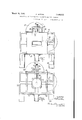
- Figure 3 is a front elevation with the bellows and lens removed.
- Figure 4 is a. View similar to Figure 3, but with the plate or the like holder, removed.
- Figure 5 is a front elevation of masking plate.
- Figure 6 is a corresponding side View partly in section.
- the camera consists of a base 1 on which the frame 2 for the camera is mounted, and which can be raised and lowered relatively to the base 1 by means of screw-jack mechanism indicated at 3 which can be of any usual form.
- the shutter of the camera is mounted on a shutter plate 4 and can be provided with any usual remote control release means 5.
- dle 10 has a gear wheel 12 meshing with another gear wheel 13 on a parallel spindle 14 similarly driven by bevel wheels 15, the rown wheel of which is mounted on a plate 16 having a graduated periphery co-operating with a fixed index 17 and a fixed rule 18.
- the carrier 19 for the plate 16 is integral with a slide 20 graduated on one side to cooperate with an index 21, which slide 20 is connected to the slide 11 having a rack edge 22 engaging with a pinion 23 on the spindle 24, which has frictionally clamped to it a double pointer 25 adapted to move over a micrometer scale 26.
- the pointer 25 has a spring catch adapted to engage with one or other of a number of perforations 27, so that its position can be accurately adjusted. It will be seen therefore, that adjustments of height of the sensitized plate relatively to the camera lens 28 will be indicated as a coarse adjustment on the indicator 21, and as a fine adjustment on the indicator 27.
- the weight of the slides, plate-holder and the like parts can be counter-balanced by means of flexible cords or the like 29 and weights 30.
- the frame 31 carrying the plateholder 9 and'its adjustment parts set forth above can be slidable in guides on the subframe 32, which is provided with a graduated edge 33 co-operating with a pointer 34, the opposite element of this frame 32 having a rack edge 35 engaging with a pinion 36 on a spindle 37, which can be frictionally clamped to a double indicating pointer 38 cooperating with a scale 39 which has perforations 40 engaging the spring pin or the like on the indicator pointer 38.
- the front bar of the plate-holder has an aperture 41 adapted to be closed by a dark slide withdrawable by means of a yoke 42 and guide rods 43.
- This mask is detachable and is carried by pins 44 engaging with sockets 45 on the camera frame, so that it can be folded down into position, or folded back out of the camera field, as required.
- This masking plate comprises a frame 46 having a pair of masks 47, 48, sliding in guides in the frame 46 provided with graduated edges cO-Operating with indicating pointers 49.
- the displacement of these masks may be effected by means of handwheels 50.51, operating the slides 48. 47 respectively through rack and pinion gearing.
- the width of the aperture mav be adiusted by means of maskslides 52. 53. operated b means of threaded snindles 54 which mask slides'52; 53. operated withindicating-pointers 55. 56. respectively.
- a photo raph c cam a comp sing a pl te-holder. a rotary miidewav for "said' plate lmlder. a. longitudinal gu dewav for said rotary gui eway. supports for said longitudinal guideway. a frame.1a l ng t nal "sa d rotary ideway. supports for said longitudinal guideway. a frame. a longitudinal guideway at ri ht angles through said fi st :gtrideway for said supports. a rotary disc mounted externally 'to said light-tight casing.
- a frame having a circularguideway suoporting said rotary disc, alongitudinal uide 'for said frame,'supports for said longitudi- ,nal guideway. a second guideway at right angles to said first guideway for said su ports and gearing between said rotary disc andsaid rotaryplate-holder. and gearmg between each guidewayfor said disc and each guideway for said plate-holder.
- a photographic camera comprising a plate-holder, a rotary guideway for said plate-holder, a longitudinal 'guideway for said rotary guideway, supports for said longitudinal guideway, a frame, a longitudinal guideway at right angles through said first 'gui'deway for said supports.
- a rotary "disc mounted externally to said light-tight casing :a frame having a circular'guideway supportlng said rotary disc, a longitudinal guide forsaid frame,vsupports for said longitudinal .guideway, a second guideway at right angles to said firstguideway for said supports, and gearing between said rotary disc and said rotary plate-holden and gearing between each guideway for said disc and each guideway' for said plate-holder, coarse and fine adjustments on each longitudinal guideway and frictional locking means for said fine adjustments.
Landscapes
- Physics & Mathematics (AREA)
- General Physics & Mathematics (AREA)
- Camera Data Copying Or Recording (AREA)
Description
March 15, 932. A, DUTTON 1,850,093
PRODUCTION OF PHOTOGRAPHIC TRANSPARENCIES FOR PRINTING Filed Feb. 27, 1951 3 Sheets-Sheet 1 INVEN TOR MM,
ATTOh/VEYS March 15, 1932. A BUTTON 1,850,003
PRODUCTION OF PHOTOGRAPHIG TRANSPAHENCIES FOR PRINTING Filed Feb. 27, 1931 3 Sheets-Sheet 2 27 0 0 40-319 25 ago 0 i n o c? I; 58 1E] /51 o MAR nvvnvroR W: H TORNLV A. DUTTON March 15, 1932.
PRODUCTION OF PHOTOGRAPHIC TRANSPARENCIES FOR PRINTING 3 Sheets-Sheet Filed Feb. 27, 1931 Vf/V TOR Mafia-,
AWORNEX;
BY wm wm? ill Patented Mar. 15, 1932 STATES ARTHUR D'UTTON, OF LIVERPOOL, ENGLAND,-ASSIGNOR TO PHOTOLINE LIMITED, OF LIVERPOOL, ENGLAND, A BRITISH COMPANY PRODUCTION OF PHOTOGBAPHIC IR-ANSPARE NGIES FOR PRINTING Application filed February 27, 1931, Serial No.
The present invention relates to improvements in photographic cameras, more particularly suitable for process work.
According to the present invention, a holder for a sensitized sheet, plate, or the like may be rotated in its own plane, and further may be displaced in its own plane in two directions at right angles to one another, these motions being relative to the shutter of the camera.
Further a mask, the aperture of which is adjustable in size and position may be interposed between the plate and the camera.
The invention is more particularly described with reference to the accompanying drawings in which Figure 1 is a side view of one form of construction of the camera, partly in section.
Figure 3 is a front elevation with the bellows and lens removed.
Figure 4 is a. View similar to Figure 3, but with the plate or the like holder, removed.
Figure 5 is a front elevation of masking plate.
Figure 6 is a corresponding side View partly in section.
The camera consists of a base 1 on which the frame 2 for the camera is mounted, and which can be raised and lowered relatively to the base 1 by means of screw-jack mechanism indicated at 3 which can be of any usual form.
The shutter of the camera is mounted on a shutter plate 4 and can be provided with any usual remote control release means 5. The
dle 10 has a gear wheel 12 meshing with another gear wheel 13 on a parallel spindle 14 similarly driven by bevel wheels 15, the rown wheel of which is mounted on a plate 16 having a graduated periphery co-operating with a fixed index 17 and a fixed rule 18.
518,822, and in Great Britain March 17, 1930.
It will consequently be seen'that any rotation of the plate 16 will cause similar rotation-of the photographic plate mounted on the base 8.
The carrier 19 for the plate 16 is integral with a slide 20 graduated on one side to cooperate with an index 21, which slide 20 is connected to the slide 11 having a rack edge 22 engaging with a pinion 23 on the spindle 24, which has frictionally clamped to it a double pointer 25 adapted to move over a micrometer scale 26. The pointer 25 has a spring catch adapted to engage with one or other of a number of perforations 27, so that its position can be accurately adjusted. It will be seen therefore, that adjustments of height of the sensitized plate relatively to the camera lens 28 will be indicated as a coarse adjustment on the indicator 21, and as a fine adjustment on the indicator 27.
The weight of the slides, plate-holder and the like parts can be counter-balanced by means of flexible cords or the like 29 and weights 30.
Similarly the frame 31 carrying the plateholder 9 and'its adjustment parts set forth above can be slidable in guides on the subframe 32, which is provided with a graduated edge 33 co-operating with a pointer 34, the opposite element of this frame 32 having a rack edge 35 engaging with a pinion 36 on a spindle 37, which can be frictionally clamped to a double indicating pointer 38 cooperating with a scale 39 which has perforations 40 engaging the spring pin or the like on the indicator pointer 38.
It will be seen therefore, that adjustments of the plate-holder 9 in horizontal plane relatively to the lens 28 are indicated as coarse adjustments on the scale 33, and line adjustments on the scale 39.
The front bar of the plate-holder has an aperture 41 adapted to be closed by a dark slide withdrawable by means of a yoke 42 and guide rods 43.
It will be preferred to provide a mask between the plate-holder and the camera. This mask is detachable and is carried by pins 44 engaging with sockets 45 on the camera frame, so that it can be folded down into position, or folded back out of the camera field, as required. 1
This masking plate comprises a frame 46 having a pair of masks 47, 48, sliding in guides in the frame 46 provided with graduated edges cO-Operating with indicating pointers 49. The displacement of these masks may be effected by means of handwheels 50.51, operating the slides 48. 47 respectively through rack and pinion gearing.
The width of the aperture mav be adiusted by means of maskslides 52. 53. operated b means of threaded snindles 54 which mask slides'52; 53. operated withindicating-pointers 55. 56. respectively.
Anv suitable lens mavloe used and f desired this ma be rep aceable so that. for instance. a distort no ens may be emp d for ohtainino modified images of an object ph t raphed.
I d clarp, that wh t I claim is:
1. A photo raph c cam a comp sing a pl te-holder. a rotary miidewav for "said' plate lmlder. a. longitudinal gu dewav for said rotary gui eway. supports for said longitudinal guideway. a frame.1a l ng t nal "sa d rotary ideway. supports for said longitudinal guideway. a frame. a longitudinal guideway at ri ht angles through said fi st :gtrideway for said supports. a rotary disc mounted externally 'to said light-tight casing. a frame having a circularguideway suoporting said rotary disc, alongitudinal uide 'for said frame,'supports for said longitudi- ,nal guideway. a second guideway at right angles to said first guideway for said su ports and gearing between said rotary disc andsaid rotaryplate-holder. and gearmg between each guidewayfor said disc and each guideway for said plate-holder.
3. A photographic camera comprising a plate-holder, a rotary guideway for said plate-holder, a longitudinal 'guideway for said rotary guideway, supports for said longitudinal guideway, a frame, a longitudinal guideway at right angles through said first 'gui'deway for said supports. a rotary "disc mounted externally to said light-tight casing, :a frame having a circular'guideway supportlng said rotary disc, a longitudinal guide forsaid frame,vsupports for said longitudinal .guideway, a second guideway at right angles to said firstguideway for said supports, and gearing between said rotary disc and said rotary plate-holden and gearing between each guideway for said disc and each guideway' for said plate-holder, coarse and fine adjustments on each longitudinal guideway and frictional locking means for said fine adjustments.
In witness whereof, I have hereunto signed my name this 2nd day of February 1931.
ARTHUR DUTTON.
Applications Claiming Priority (1)
| Application Number | Priority Date | Filing Date | Title |
|---|---|---|---|
| GB1850003X | 1930-03-17 |
Publications (1)
| Publication Number | Publication Date |
|---|---|
| US1850003A true US1850003A (en) | 1932-03-15 |
Family
ID=10891928
Family Applications (1)
| Application Number | Title | Priority Date | Filing Date |
|---|---|---|---|
| US518822A Expired - Lifetime US1850003A (en) | 1930-03-17 | 1931-02-27 | Production of photographic transparencies for printing |
Country Status (1)
| Country | Link |
|---|---|
| US (1) | US1850003A (en) |
-
1931
- 1931-02-27 US US518822A patent/US1850003A/en not_active Expired - Lifetime
Similar Documents
| Publication | Publication Date | Title |
|---|---|---|
| US2160750A (en) | Photographic composing machine | |
| US1911142A (en) | Apparatus for correcting tilted photographs | |
| US1801458A (en) | Photographic apparatus | |
| US2255319A (en) | Photographic enlarger | |
| US3228284A (en) | Photographic printer | |
| US2999443A (en) | Optical filter compensation means coupled to exposure-responsive device | |
| US1850003A (en) | Production of photographic transparencies for printing | |
| US1846972A (en) | Precision copying camera | |
| US2727431A (en) | Automatic focusing device | |
| US3071056A (en) | Photographic camera | |
| US2917968A (en) | Field changing means for viewfinder | |
| US3295408A (en) | Optical apparatus for adjusting copyto-image ratios in graphic arts photography | |
| US2044184A (en) | Apparatus for making negatives | |
| US2113580A (en) | Adjustable film gate | |
| US2506131A (en) | Peristereoscopic apparatus for taking, reeducing, or enlarging pictures | |
| US1195225A (en) | huebner | |
| US2481677A (en) | Camera finder and focus interlocking mechanism | |
| US3741098A (en) | Camera system | |
| US1873571A (en) | Focusing device for motion picture cameras | |
| US2295801A (en) | Two-size camera | |
| US1635014A (en) | Photographic-printing machine | |
| US3253503A (en) | Photographic copying apparatus | |
| US3286587A (en) | Photographic copying apparatus | |
| US2080604A (en) | Apparatus for making stereoscopic positives from negatives | |
| US1832026A (en) | Photographic printing apparatus |