US184916A - Improvement in earth-augers - Google Patents
Improvement in earth-augers Download PDFInfo
- Publication number
- US184916A US184916A US184916DA US184916A US 184916 A US184916 A US 184916A US 184916D A US184916D A US 184916DA US 184916 A US184916 A US 184916A
- Authority
- US
- United States
- Prior art keywords
- earth
- auger
- improvement
- augers
- attached
- Prior art date
- Legal status (The legal status is an assumption and is not a legal conclusion. Google has not performed a legal analysis and makes no representation as to the accuracy of the status listed.)
- Expired - Lifetime
Links
- 238000005192 partition Methods 0.000 description 3
- 238000010276 construction Methods 0.000 description 2
- 208000025814 Inflammatory myopathy with abundant macrophages Diseases 0.000 description 1
Images
Classifications
-
- E—FIXED CONSTRUCTIONS
- E21—EARTH OR ROCK DRILLING; MINING
- E21B—EARTH OR ROCK DRILLING; OBTAINING OIL, GAS, WATER, SOLUBLE OR MELTABLE MATERIALS OR A SLURRY OF MINERALS FROM WELLS
- E21B11/00—Other drilling tools
- E21B11/005—Hand operated drilling tools
Definitions
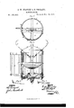
- Figure l is a top view of our improved Well-auger, part being broken away to show the construction.
- Fig. 2 is a side view of the same, part of the case being turned back.
- Figs. 3 and 4 are detail views of the lower reamers.
- the object of this invention is to furnish an improved well-auger, which shall be so constructed as to enable a much larger hole to be y bored than the diameter ofthe auger, andwhich shall be easily operated, and effective in operation, moving the small stones from the center toward the rim, so that they may be taken up by the cutters.
- A represents the lower section of the shaft, to the lower part of which is attached a Vertical squarc frame, B, the upper end of which is strengthened by the braces O.
- a Vertical squarc frame, B To each of the side bars of the frame B are hinged semicylindrical plates H, which plates H, when closed together, form the case of the auger, so that they may be opened to empty the auger.
- the hinges of the plates H are sliding or detachable, so that the said plates may be detached, if desired, for convenience in emptying the auger.
- a screw-drill or reamer-shaped piece, D To the lower end ofthe shaft A is attached a screw-drill or reamer-shaped piece, D, to lead B, and project beyond the case H, so as to cut a hole of a larger diameter than the case H.
- the reamers J may be made to project more or less to cut a larger or smaller hole, by adjusting the block L upon the shaft A.
- the earth loosened by the reamers J falls into the upper part of the case H, and is received upon the partition K, attached to the shaf't A to relieve the cutters E from its weight.
- rIhe partition K may be made dat, or conical, or V-shaped, as shown in Fig. 2.
- the latter construction is preferred, as it facilitates the discharge ofthe earth when the case H is opened.
- L are reamers, to be attached to the lower end of the auger when the hole has been sunk nearly to the requireddepth to ream out the lower part of the hole below the point where the reamers J can operate.
- the auger into the ground, and push the earth justable on shaft A, as and for the purpose and stones outward from the center, so that they may be taken up by the cutters E attached to the frame B, and to the rim F attached to the bars or frame that supports the cutters E.
- the cutters E are made of moldboard shape, which enables them to take up stones nearer to the center than they otherwise could.
Landscapes
- Engineering & Computer Science (AREA)
- Life Sciences & Earth Sciences (AREA)
- Geology (AREA)
- Mining & Mineral Resources (AREA)
- Mechanical Engineering (AREA)
- Physics & Mathematics (AREA)
- Environmental & Geological Engineering (AREA)
- Fluid Mechanics (AREA)
- General Life Sciences & Earth Sciences (AREA)
- Geochemistry & Mineralogy (AREA)
- Processing Of Stones Or Stones Resemblance Materials (AREA)
- Earth Drilling (AREA)
Description
a.. W. sHA'PLEYx D.,PH1LLIPs.
- EARTH-AUGER.
Patented Nov. 28,1876.
INI
ii IHII? IH Il imams.'
NJIERS. PHOTO-LITMOGRAPHER. WASHINTON. D. C4
UETTEE STATES PATENT QEETGE..
IMPROVEMENT IN EARTH-AUGERS.
Specification forming part of Letters Patent No. 184,916, dated November 28, 1876; application tiled April 25, 1876.
To all whom it may concern:
Be it vknown that we, GEORGE W. SHAP- LEY and DANIEL PHILLIPS, of Austin, in the county of Mower and State of Minnesota, have invented a new and useful Improvement in Well-Auger, of which the following is a specification:
Figure l is a top view of our improved Well-auger, part being broken away to show the construction. Fig. 2 is a side view of the same, part of the case being turned back. Figs. 3 and 4 are detail views of the lower reamers.
Similar letters of reference indicate corresponding parts.
The object of this invention is to furnish an improved well-auger, which shall be so constructed as to enable a much larger hole to be y bored than the diameter ofthe auger, andwhich shall be easily operated, and effective in operation, moving the small stones from the center toward the rim, so that they may be taken up by the cutters.
The invention will first be described in connection with drawing, and then pointed out in the claims.
A represents the lower section of the shaft, to the lower part of which is attached a Vertical squarc frame, B, the upper end of which is strengthened by the braces O. To each of the side bars of the frame B are hinged semicylindrical plates H, which plates H, when closed together, form the case of the auger, so that they may be opened to empty the auger. The hinges of the plates H are sliding or detachable, so that the said plates may be detached, if desired, for convenience in emptying the auger.
To the lower end ofthe shaft A is attached a screw-drill or reamer-shaped piece, D, to lead B, and project beyond the case H, so as to cut a hole of a larger diameter than the case H.
The reamers J may be made to project more or less to cut a larger or smaller hole, by adjusting the block L upon the shaft A.
The earth loosened by the reamers J falls into the upper part of the case H, and is received upon the partition K, attached to the shaf't A to relieve the cutters E from its weight.
rIhe partition K may be made dat, or conical, or V-shaped, as shown in Fig. 2. The latter construction is preferred, as it facilitates the discharge ofthe earth when the case H is opened.
L are reamers, to be attached to the lower end of the auger when the hole has been sunk nearly to the requireddepth to ream out the lower part of the hole below the point where the reamers J can operate.
Having thus described our invention, We claim as new and desire to secure by Letters Patentl. The combination of shaft A, frame B, and semi-cylindrical plates H, the latter detachably hinged, substantially as and for the purpose described.
2. The combination, with shaft A, frame B, and Aplates H, of thedrill-cutter D, mold-board cutters E, rim F, and points G, arranged substantially as and for the purpose specified.
3. The reamers J, attached to blocks I, ad-
the auger into the ground, and push the earth justable on shaft A, as and for the purpose and stones outward from the center, so that they may be taken up by the cutters E attached to the frame B, and to the rim F attached to the bars or frame that supports the cutters E. The cutters E are made of moldboard shape, which enables them to take up stones nearer to the center than they otherwise could.
To the cutters E and the rim F are attached points G, which 'project a little beyond the said rim F, and are made something like described.
4. The combination of the partition K with the shaft A, and the middle part of the case H, substantially as herein shown and described.
GEORGE W. SHAPLEY. DANIEL PHILLIPS. Witnesses:
F. A. ELDER,
J. SNYMUNDSON.
Publications (1)
| Publication Number | Publication Date |
|---|---|
| US184916A true US184916A (en) | 1876-11-28 |
Family
ID=2254321
Family Applications (1)
| Application Number | Title | Priority Date | Filing Date |
|---|---|---|---|
| US184916D Expired - Lifetime US184916A (en) | Improvement in earth-augers |
Country Status (1)
| Country | Link |
|---|---|
| US (1) | US184916A (en) |
-
0
- US US184916D patent/US184916A/en not_active Expired - Lifetime
Similar Documents
| Publication | Publication Date | Title |
|---|---|---|
| US187705A (en) | Improvement in earth-augers | |
| US21945A (en) | Ghaut-separator | |
| US318653A (en) | Earth-auger | |
| US167628A (en) | Improvement in earth-augers | |
| US31551A (en) | Improved ditching-machine | |
| US182107A (en) | Improvement in earth-augers | |
| US143963A (en) | Improvement in earth-augers | |
| US120423A (en) | Improvement in walking-planters | |
| US118196A (en) | Improvement in post-hole augers | |
| US127224A (en) | Improvement in cotton-seed cleaners | |
| US169115A (en) | Improvement in earth-augers | |
| US161190A (en) | Improvement in well-reamers | |
| US138788A (en) | Improvement in means for operating earth-augers | |
| US386397A (en) | Earth-auger | |
| US210301A (en) | Improvement in well-augers | |
| US35435A (en) | Improvement in potato-diggers | |
| US727322A (en) | Earth-auger. | |
| US180787A (en) | Improvement in earth-augers | |
| US410311A (en) | Expansion-drill | |
| US79356A (en) | Xjohn- b b | |
| US101160A (en) | Improved earth-auger | |
| US819739A (en) | Post-hole auger. | |
| US201950A (en) | Improvement in well-augers | |
| US225508A (en) | Earth-auger | |
| US235288A (en) | Drill for coal |