US184601A - Improvement in churns - Google Patents
Improvement in churns Download PDFInfo
- Publication number
- US184601A US184601A US184601DA US184601A US 184601 A US184601 A US 184601A US 184601D A US184601D A US 184601DA US 184601 A US184601 A US 184601A
- Authority
- US
- United States
- Prior art keywords
- shaft
- churn
- box
- dashers
- churns
- Prior art date
- Legal status (The legal status is an assumption and is not a legal conclusion. Google has not performed a legal analysis and makes no representation as to the accuracy of the status listed.)
- Expired - Lifetime
Links
- 238000010276 construction Methods 0.000 description 2
- 241001342895 Chorus Species 0.000 description 1
- HAORKNGNJCEJBX-UHFFFAOYSA-N cyprodinil Chemical compound N=1C(C)=CC(C2CC2)=NC=1NC1=CC=CC=C1 HAORKNGNJCEJBX-UHFFFAOYSA-N 0.000 description 1
- 238000003780 insertion Methods 0.000 description 1
- 230000037431 insertion Effects 0.000 description 1
- 239000008267 milk Substances 0.000 description 1
- 210000004080 milk Anatomy 0.000 description 1
- 235000013336 milk Nutrition 0.000 description 1
- 238000012856 packing Methods 0.000 description 1
Images
Classifications
-
- B—PERFORMING OPERATIONS; TRANSPORTING
- B01—PHYSICAL OR CHEMICAL PROCESSES OR APPARATUS IN GENERAL
- B01F—MIXING, e.g. DISSOLVING, EMULSIFYING OR DISPERSING
- B01F27/00—Mixers with rotary stirring devices in fixed receptacles; Kneaders
- B01F27/80—Mixers with rotary stirring devices in fixed receptacles; Kneaders with stirrers rotating about a substantially vertical axis
- B01F27/84—Mixers with rotary stirring devices in fixed receptacles; Kneaders with stirrers rotating about a substantially vertical axis with two or more stirrers rotating at different speeds or in opposite directions about the same axis
Definitions
- my invention consists in the construction and arrangement of a churn, and the means for propelling the same, as will be hereinafter more fully set forth.
- FIG. 2 is a longitudinal section of the same, through the line :20 ac, Fig. 1.
- Fig. 3 is a transverse vertical section of the churn-box, through the line y y, Fig. l; and
- Fig. 4 is an end view of the same.
- A represents the main frame-work of my machine, constructed in any suitable manner, so as to contain the working parts thereof.
- B represents the churn-box, constructed with curved bottom, and held in the frame A by a set-screw, b, pressing it against two pins or projections, a 0,.
- Within the box are two sets of dashers, one opera-ting within the other.
- the inner set consists of two parallel arms, 0 0, having their ends connected by inclined dashers D D formed with beveled edges.
- the outer set is constructed in the same manner, of two side arms, 0 O, with inclined dashers D D connecting their ends.
- each arm 0 In the center of each arm 0 is secured ajournal, d, which passes through the centers of the arms 0, which latter arms are perforated for that purpose.
- the journal at at one end of the churn is provided with a flange or colv ler, e, and has its bearing in a bisected box, E attached to the end of the churn, one part of said box being stationary, and the other pivoted so that the box can be easily opened and closed for the removal and insertion of the dashers.
- the other journal d passes through a flanged sleeve, f, bolted or otherwise fastened to the outer side of the outer dasher-arrn C, said sleeve passing through an aperture in that end of the churn.
- the outer end of this journal is coupled to a shaft,
- the shaft G is secured a beveled pinion, I, and the two pinions I and I mesh with a cog-wheel, K, secured upon a shaft, L, extending at right angles with the shaft G.
- the two pinions I I are revolved in opposite directions, and as one of them is attached to the shaft connected with the inner set of dashers, and the other connected with the outer set of dashers, the two sets of dashers are revolved rapidly in opposite directions.
- the shaft L may be rotated by any power by applying a belt on a pulley, M, Fig. 4, on its outer end; but when not much power is required, I propose to operate the churn by a person rocking in a rocking-chair,
- This chair is pivoted on a shaft, 0,
- the churn-box B having two sets of horizontally arranged dashers revolving in opposite directions, and the bisected box IE, journals d d, and the flanged sleeve f, all constructed, arranged, and operated substantially as and for the purposes herein set forth.
Landscapes
- Chemical & Material Sciences (AREA)
- Chemical Kinetics & Catalysis (AREA)
- Special Chairs (AREA)
Description
2 Sheets-Sheet 1.
O. ELIASOIL.
CHURNS.
Patented Nov. 21,1876.
INVENTOR PATENT Orr-Ton.
OLAF ELIASON, OF STERLING, ILLINOIS.
IMPROVEMENT IN CHURNS.
Specification forming part of Letters Patent No. 184,601, dated November 21, 1876 application filed April 24, 1876.
To all whom it may concern:
Be it known that I, 0. ELIASON, of Sterling, in the county of Whitesides, and in the State of Illinois, have invented certain new and useful Improvements in Chorus; and do hereby declare that the following is a full, clear, and exact description thereof, reference being had to the accompanying drawings, and to the letters of reference marked thereon,
making a part'of this specification.
The nature of my invention consists in the construction and arrangement of a churn, and the means for propelling the same, as will be hereinafter more fully set forth.
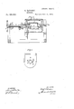
In order to enable others skilled in the art to which my invention appertains to make and use the same, I will now proceed to describe its construction and operation, referring to the annexed drawings, in which- Figure l is a plan view of my invention. Fig. 2 is a longitudinal section of the same, through the line :20 ac, Fig. 1. Fig. 3 is a transverse vertical section of the churn-box, through the line y y, Fig. l; and Fig. 4 is an end view of the same.
A represents the main frame-work of my machine, constructed in any suitable manner, so as to contain the working parts thereof. B represents the churn-box, constructed with curved bottom, and held in the frame A by a set-screw, b, pressing it against two pins or projections, a 0,. Within the box are two sets of dashers, one opera-ting within the other. The inner set consists of two parallel arms, 0 0, having their ends connected by inclined dashers D D formed with beveled edges. The outer set is constructed in the same manner, of two side arms, 0 O, with inclined dashers D D connecting their ends. In the center of each arm 0 is secured ajournal, d, which passes through the centers of the arms 0, which latter arms are perforated for that purpose.' The journal at at one end of the churn is provided with a flange or colv ler, e, and has its bearing in a bisected box, E attached to the end of the churn, one part of said box being stationary, and the other pivoted so that the box can be easily opened and closed for the removal and insertion of the dashers. The other journal d passes through a flanged sleeve, f, bolted or otherwise fastened to the outer side of the outer dasher-arrn C, said sleeve passing through an aperture in that end of the churn. The outer end of this journal is coupled to a shaft,
G, having its bearings in the frame A, and provided with a fly-wheel, H. The end of the sleeve f is coupled to the hub h of a beveled pinion, I, placed loosely on the shaft G, and the joint inclosed by a bisected packing box, J, the two parts of which are pivoted to the churn, and held by a guard, 70, as shown in Fig. 4.
0n the shaft G is secured a beveled pinion, I, and the two pinions I and I mesh with a cog-wheel, K, secured upon a shaft, L, extending at right angles with the shaft G. When the shaft L is rotated the two pinions I I are revolved in opposite directions, and as one of them is attached to the shaft connected with the inner set of dashers, and the other connected with the outer set of dashers, the two sets of dashers are revolved rapidly in opposite directions.
The shaft L may be rotated by any power by applying a belt on a pulley, M, Fig. 4, on its outer end; but when not much power is required, I propose to operate the churn by a person rocking in a rocking-chair,
N. This chair is pivoted on a shaft, 0,
in an auxiliary frame, A,' attached to the main frame A, and has one of its rockers, P, extendeddbrward a suitable distance. To the front end of this rocker is pivoted an arm, It, which is connected to a crank, S, on the end of the shaft L. By rocking the chair back and forth, said shaft thus obtains a rotary motion, thereby operating the churndashers.
Vis the lid of the churn, provided with air-passages a; w, and under the same, to the lid, is attached a trough, m, to prevent the milk splashing up and through said air-passages.
Having thus fully described my invention, what I claim as new, and desire to secure by Letters Patent, is-
The churn-box B, having two sets of horizontally arranged dashers revolving in opposite directions, and the bisected box IE, journals d d, and the flanged sleeve f, all constructed, arranged, and operated substantially as and for the purposes herein set forth.
In testimony that I claim the foregoing I have hereunto set my hand this 5th day of April, 1876.
OLAF ELIASON.
Witnesses:
WM. LANE, WM. A. VAN ASDEL-
Publications (1)
| Publication Number | Publication Date |
|---|---|
| US184601A true US184601A (en) | 1876-11-21 |
Family
ID=2254006
Family Applications (1)
| Application Number | Title | Priority Date | Filing Date |
|---|---|---|---|
| US184601D Expired - Lifetime US184601A (en) | Improvement in churns |
Country Status (1)
| Country | Link |
|---|---|
| US (1) | US184601A (en) |
Cited By (1)
| Publication number | Priority date | Publication date | Assignee | Title |
|---|---|---|---|---|
| US20050123544A1 (en) * | 2000-05-26 | 2005-06-09 | Neuralab Limited | Prevention and treatment of amyloidogenic disease |
-
0
- US US184601D patent/US184601A/en not_active Expired - Lifetime
Cited By (2)
| Publication number | Priority date | Publication date | Assignee | Title |
|---|---|---|---|---|
| US20050123544A1 (en) * | 2000-05-26 | 2005-06-09 | Neuralab Limited | Prevention and treatment of amyloidogenic disease |
| US20060121038A9 (en) * | 2000-05-26 | 2006-06-08 | Neuralab Limited | Prevention and treatment of amyloidogenic disease |
Similar Documents
| Publication | Publication Date | Title |
|---|---|---|
| US184601A (en) | Improvement in churns | |
| US471337A (en) | Churn | |
| US213127A (en) | Improvement in churns | |
| US225644A (en) | Churn-motor | |
| US144290A (en) | Improvement in churn-dashers | |
| US1070147A (en) | Churn. | |
| US412934A (en) | Churn | |
| US219658A (en) | Improvement in churns | |
| US412250A (en) | Churn | |
| US437331A (en) | Churn | |
| US470210A (en) | John hosking pett | |
| US242275A (en) | Churning cream | |
| US416610A (en) | Herriott | |
| US347312A (en) | barnesley | |
| US428987A (en) | Churn-power | |
| US182185A (en) | Improvement in churns | |
| US639330A (en) | Churn. | |
| US461247A (en) | Churn | |
| US201633A (en) | Improvement in rocking churns with vibrating dashers | |
| US247144A (en) | Frank m | |
| US314399A (en) | Churn | |
| US242048A (en) | Paddle-wheel | |
| US325084A (en) | Churn | |
| US329443A (en) | Geoege feedebick day | |
| US195368A (en) | Improvement in churn-motors |