US1834026A - Lath holder - Google Patents
Lath holder Download PDFInfo
- Publication number
- US1834026A US1834026A US470496A US47049630A US1834026A US 1834026 A US1834026 A US 1834026A US 470496 A US470496 A US 470496A US 47049630 A US47049630 A US 47049630A US 1834026 A US1834026 A US 1834026A
- Authority
- US
- United States
- Prior art keywords
- laths
- clips
- frame
- lath
- joists
- Prior art date
- Legal status (The legal status is an assumption and is not a legal conclusion. Google has not performed a legal analysis and makes no representation as to the accuracy of the status listed.)
- Expired - Lifetime
Links
- 239000000463 material Substances 0.000 description 2
- 238000010276 construction Methods 0.000 description 1
- 239000002184 metal Substances 0.000 description 1
- 239000011505 plaster Substances 0.000 description 1
- 239000002699 waste material Substances 0.000 description 1
- 239000002023 wood Substances 0.000 description 1
Images

Classifications
-
- B—PERFORMING OPERATIONS; TRANSPORTING
- B25—HAND TOOLS; PORTABLE POWER-DRIVEN TOOLS; MANIPULATORS
- B25B—TOOLS OR BENCH DEVICES NOT OTHERWISE PROVIDED FOR, FOR FASTENING, CONNECTING, DISENGAGING OR HOLDING
- B25B5/00—Clamps
- B25B5/06—Arrangements for positively actuating jaws
-
- Y—GENERAL TAGGING OF NEW TECHNOLOGICAL DEVELOPMENTS; GENERAL TAGGING OF CROSS-SECTIONAL TECHNOLOGIES SPANNING OVER SEVERAL SECTIONS OF THE IPC; TECHNICAL SUBJECTS COVERED BY FORMER USPC CROSS-REFERENCE ART COLLECTIONS [XRACs] AND DIGESTS
- Y10—TECHNICAL SUBJECTS COVERED BY FORMER USPC
- Y10S—TECHNICAL SUBJECTS COVERED BY FORMER USPC CROSS-REFERENCE ART COLLECTIONS [XRACs] AND DIGESTS
- Y10S269/00—Work holders
- Y10S269/904—Work holder for positioning elements of building in installed location
Definitions
- This invention relates to new and useful improvements in devices for use by lathers, and more particularly it pertainsto a means for properly positioning aplufrality oflaths simultaneously upon the wall the studding of which forms the means to which the'laths areattached.
- V p p It is one of the objects of theinvention to provide a' device for holding a plurality of laths which device will permit of the p ositioning,and securing in position of a greater number of laths in a given periodjof time than is possible in the ordinary manner, M
- a further object of the invention residesin the provision of means whereby the lathswill be uniformly spaced with respect to one another, thereby providing for greater accuracy in the placing of the layers, and a considerable saving in plaster usedwith which the laths are covered, since the spaces between the layers will. at all times be uniform.
- a further object of the invention resides in the provision of a device, the use of which will entirely eliminate. the necessity of building scaifolds, since the device may ⁇ beused from a step ladder or similar device as distinguished from scaffolding as commonly used, thus eliminatingall expense such as cost of material, waste of material and the labor for erecting and taking down such scaffolds.
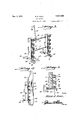
- Figure 1 is a view in elevation illustrating n the manner of use of the device for placing a plurality of laths in position upon the studding or joists of a side wall
- Figure 2 is a top plan View thereof
- Figure 3 is a perspective view of the frame per se
- Figure 4 is a vertical sectional view through the frame, and;
- Pre n e t- .01 een is 9f .aei em e nii is ngj e 11 17 1 9 1Q eenneeted; et e by n v r e y e t ding bets .I 'ude l'eb l that hes m mb rs 1 .196 adj stl el ti e to, .ee e he a d t0 hisend huber 11 is provided 9 on (if.
- eee other may be had by alsuitable loosening and h eni gef t e W g 1 1 a j i Ea th end me e flee fr eeerlue f; o i e ie t 1 f 5 eeeur difl e ee et rende heee e p ie ed teelt fy eltl n y r..
- n n ee of the frame it being understood that' the ag ee as n cha ge deeup ei fram'ejis supported from the uppermostf lathl or from any other suita blesupport attached h ie s s by sa d et 301 H Additional securing means be emplfoye if d e t preve teufiwerfil .fi 'qii ment of the upper end of the frame when" it is in proper position, and in the present embodiment of the invention, this means consists of a sleeve 35 slidably mounted upon the upper most rod 11. Universally connected to the sleeve 35 as at 36, there is a member 37 in the form of an arm, the outer or free end of which carries a suitable nail spike or the like 38. The operation of the device thus far described is as follows.
- the laths are positioned within the several spring clips 15 by placing them therein on edge and rocking them sideways until they occupy the position in which they are illustrated in Figure 4.
- lVith the frame thus filled with laths the feet 30 are engaged with the uppermost lath already secured to the joists of the side walls being lathed, after which the arm 37 is swung upwardly, and the nail 38 thereof is driven into the joists as illustrated in Figure 4.
- WVith the device thus positioned it will be seen by reference to Figure 1 that the laths will overlap the several joists in proper relation, and that it is only necessary to drive a few nails in order to simultaneously secure a number of laths to the joists. It will also be noted that after the laths have been secured in position, it is only necessary to grasp the handle members 40 to remove the entire frame from the nailed laths, the resiliency of the spring clips 15 readily permitting of the detachment of the frame.
- right angular clips such as 41 are pro- 'vided. These clips are mounted as at 42 in the lower end of each of the members 10, and have a right angular extension 43 which is adapted to engage behind the outside laths already positioned upon the ceiling. Surrounding these clips there is a spring 44 and theopposite ends of said clips are formed with a handle 45, the spring being positioned between the innermost portion of the handle 45 and its respective member 10.
- the present invention provides means by which a. plurality of laths may be simultaneously placed in position for nailing upon a wall, and that the several laths may by the device of the present invention be held in such position until they are securely nailed in place upon the wall.
Landscapes
- Engineering & Computer Science (AREA)
- Mechanical Engineering (AREA)
- Portable Nailing Machines And Staplers (AREA)
Description
M E. HALL LATH HOLDER Filed July 24, 1930 2 Sheets-Sheet l Inventor Mm; if flzih A ttorney Dec. 1, 1931.
M. E. HALL LATH HOLDER Filed July 24, 1930 2 Sheets-Sheet 2 flf/MJ 16? A4445 Inv'hlor A llorney Patented Dec. 1, 1931 sures p 7 1w en mamess s. first, irigai'rsqiiaigfj iswgsn dietitians T6 xfiiifiiiii WIDEMKIER," 0F 'MANAS'QUAN, NEW JER$EY Hes-sm- A'p neaadn mutants 24, 1930;- Serial no. 4701496.
This invention relates to new and useful improvements in devices for use by lathers, and more particularly it pertainsto a means for properly positioning aplufrality oflaths simultaneously upon the wall the studding of which forms the means to which the'laths areattached. V p p It is one of the objects of theinvention to provide a' device for holding a plurality of laths which device will permit of the p ositioning,and securing in position of a greater number of laths in a given periodjof time than is possible in the ordinary manner, M
.A further object of the invention residesin the provision of means whereby the lathswill be uniformly spaced with respect to one another, thereby providing for greater accuracy in the placing of the layers, and a considerable saving in plaster usedwith which the laths are covered, since the spaces between the layers will. at all times be uniform.
It is a further object of the invention to provide a device of the'aforeinentionedcharacter which will materially decrease the amount of labor necessaryto secure inposition'a given-number of laths- U p A further object of the invention resides in the provision of a device, the use of which will entirely eliminate. the necessity of building scaifolds, since the device may} beused from a step ladder or similar device as distinguished from scaffolding as commonly used, thus eliminatingall expense such as cost of material, waste of material and the labor for erecting and taking down such scaffolds.
Other objects of the invention will appear as the nature of the invention is better understood, and in this connection, reference will be had to the accompanying drawings, in whlch;
Figure 1 is a view in elevation illustrating n the manner of use of the device for placinga plurality of laths in position upon the studding or joists of a side wall,
Figure 2 is a top plan View thereof,
Figure 3 is a perspective view of the frame per se,
Figure 4 is a vertical sectional view through the frame, and;
w f 91 e, either porti f.. heif e e.- r, e
A dev eev letru te n. eeee de zvith h Pre n e t- .01 een is 9f .aei em e nii is ngj e 11 17 1 9 1Q eenneeted; et e by n v r e y e t ding bets .I 'ude l'eb l that hes m mb rs 1 .196 adj stl el ti e to, .ee e he a d t0 hisend huber 11 is provided 9 on (if. itee ds w th a t r ade P ie edePted o ebee g ged y. a p ur y of Wins nu ser m n fastesing 11162111513, The opposite end of thebar l lv s provided withnuts l4 between which he o h r e d ber i e emped-il BY thi mean t vil i obv us teelit in djustment of f 'e .nle' i v1.0 rel tive 9. eee other may be had by alsuitable loosening and h eni gef t e W g 1 1 a j i Ea th end me e flee fr eeerlue f; o i e ie t 1 f 5 eeeur difl e ee et rende heee e p ie ed teelt fy eltl n y r.. e en y eld and ee y plurality f th eu h ,dee g te i i Fi u e y fe fe e to F ure 5 i ,vi lbei etedthe ee fthe e m mb s li ieeee ase 01'- e l ha g le 9 2mm spel mee Ye s. etfl 0e lpli d gue :21 Th s can- -rueti n ,pr v de .e. p ra i y: t. r si ie eha ine ei a d t e e he' me s erefedepte to reeeiirethe la h it being under eedfihe e iel alle2 f th ehenne ev ieh re ilien x d e e e; ,e leug t fi ...bett m W ll, 1 th re f, rt Pr v n a he pass n b wee ithe le el? e o t e res l n M1124 ieth bo tom 18 eie'e h nelc The l ee;iee Pp ted n operat pee tion1 for nailing laths upon thejoi sts o i side Weills y et 0 the e 0-. Theeevfe -riefreb y" eeniiit e sheet et l. exten i jhe ns afidew w dly, u e ente endfilr ,Whie P ovid s, s lde 32 apt feremseeemen e nd the uppe -me K l h already a led t th joi ts. ie .pre 'ent. n n ee of the frame, it being understood that' the ag ee as n cha ge deeup ei fram'ejis supported from the uppermostf lathl or from any other suita blesupport attached h ie s s by sa d et 301 H Additional securing means be emplfoye if d e t preve teufiwerfil .fi 'qii ment of the upper end of the frame when" it is in proper position, and in the present embodiment of the invention, this means consists of a sleeve 35 slidably mounted upon the upper most rod 11. Universally connected to the sleeve 35 as at 36, there is a member 37 in the form of an arm, the outer or free end of which carries a suitable nail spike or the like 38. The operation of the device thus far described is as follows.
The laths are positioned Within the several spring clips 15 by placing them therein on edge and rocking them sideways until they occupy the position in which they are illustrated in Figure 4. lVith the frame thus filled with laths, the feet 30 are engaged with the uppermost lath already secured to the joists of the side walls being lathed, after which the arm 37 is swung upwardly, and the nail 38 thereof is driven into the joists as illustrated in Figure 4. WVith the device thus positioned, it will be seen by reference to Figure 1 that the laths will overlap the several joists in proper relation, and that it is only necessary to drive a few nails in order to simultaneously secure a number of laths to the joists. It will also be noted that after the laths have been secured in position, it is only necessary to grasp the handle members 40 to remove the entire frame from the nailed laths, the resiliency of the spring clips 15 readily permitting of the detachment of the frame.
For supporting the frame and the laths carried thereby in position upon a ceiling wall, right angular clips such as 41 are pro- 'vided. These clips are mounted as at 42 in the lower end of each of the members 10, and have a right angular extension 43 which is adapted to engage behind the outside laths already positioned upon the ceiling. Surrounding these clips there is a spring 44 and theopposite ends of said clips are formed with a handle 45, the spring being positioned between the innermost portion of the handle 45 and its respective member 10.
As illustrated in Figure 3, the normal position of the right angular ends 43 of these clips 41 is at right angles to the member 10.,
but when they are positioned to support or suspend the frame and laths carried thereby from the ceiling, they are turned so that they project downwardly as illustrated in Figure 5, in which position they occupy a position within notches 47 formed in the feet 30 heretofore' described. To operate the clips 41 to turn them to the position in which they are shown in Figure 5 from the position in which they are shown in Figure 3 or vice versa, it is only necessary to grip the handle portions 45 thereof and turn the same. In positioning the device against the ceiling wall, the right angular extensions 43 of the clips 41 are engaged behind the outside lath already nailed in position, and the resiliency of the springs 44 will insure the proper positioning of the clips 41 behind the laths already secured to retain the device in position. In addition to this means, the arm 37 with its nail or other fastening 38 is also employed to retain the device in position upon the ceiling.
From the foregoing, it will be readily apparent that the present invention provides means by which a. plurality of laths may be simultaneously placed in position for nailing upon a wall, and that the several laths may by the device of the present invention be held in such position until they are securely nailed in place upon the wall.
Furthermore it will be apparent that by use of such a device, the labor and expense generally attendant a lathing operation will be materially reduced, and that the laths will have a more uniform arrangement than is possible by singly placing the laths in position by hand without the use of suitable spacing means.
Although certain parts of the device have been illustrated as constructed of wood, it will be understood that the same may be of metal if so desired.
\Vhile the device has been herein illustrated in what may be termed its preferred form, it is to be understood that the invention is not to be limited to the construction illustrate-d, but that it may be practiced in many tioned means being universally adjustable with relation to said frame.
In testimony whereof I afiix my signature.
MILES E. HALL.
Priority Applications (1)
| Application Number | Priority Date | Filing Date | Title |
|---|---|---|---|
| US470496A US1834026A (en) | 1930-07-24 | 1930-07-24 | Lath holder |
Applications Claiming Priority (1)
| Application Number | Priority Date | Filing Date | Title |
|---|---|---|---|
| US470496A US1834026A (en) | 1930-07-24 | 1930-07-24 | Lath holder |
Publications (1)
| Publication Number | Publication Date |
|---|---|
| US1834026A true US1834026A (en) | 1931-12-01 |
Family
ID=23867847
Family Applications (1)
| Application Number | Title | Priority Date | Filing Date |
|---|---|---|---|
| US470496A Expired - Lifetime US1834026A (en) | 1930-07-24 | 1930-07-24 | Lath holder |
Country Status (1)
| Country | Link |
|---|---|
| US (1) | US1834026A (en) |
Cited By (8)
| Publication number | Priority date | Publication date | Assignee | Title |
|---|---|---|---|---|
| US2962281A (en) * | 1955-05-20 | 1960-11-29 | Leonard L Hodgson | Mounting device for outlet boxes |
| US3054611A (en) * | 1959-08-21 | 1962-09-18 | Carl L Thon | Attachment for installing wallboard and insulation |
| DE1173638B (en) * | 1961-11-16 | 1964-07-09 | Hoesch Ag | Pliers-like device for holding large panels for a false ceiling |
| US5190266A (en) * | 1992-04-23 | 1993-03-02 | John Barrera | Decking clamp and spacer |
| US5491905A (en) * | 1994-04-26 | 1996-02-20 | Jablonski; Jeffrey C. | Apparatus for accurately spacing railing spindles |
| US20150197960A1 (en) * | 2014-01-13 | 2015-07-16 | Trevor Woods | Fence Installation Tool |
| WO2015157795A1 (en) * | 2014-04-15 | 2015-10-22 | Weeks Holdings Pty Ltd | Purlin fixing tool |
| US20230287694A1 (en) * | 2022-03-12 | 2023-09-14 | Khristian Johnson | Installation Device |
-
1930
- 1930-07-24 US US470496A patent/US1834026A/en not_active Expired - Lifetime
Cited By (8)
| Publication number | Priority date | Publication date | Assignee | Title |
|---|---|---|---|---|
| US2962281A (en) * | 1955-05-20 | 1960-11-29 | Leonard L Hodgson | Mounting device for outlet boxes |
| US3054611A (en) * | 1959-08-21 | 1962-09-18 | Carl L Thon | Attachment for installing wallboard and insulation |
| DE1173638B (en) * | 1961-11-16 | 1964-07-09 | Hoesch Ag | Pliers-like device for holding large panels for a false ceiling |
| US5190266A (en) * | 1992-04-23 | 1993-03-02 | John Barrera | Decking clamp and spacer |
| US5491905A (en) * | 1994-04-26 | 1996-02-20 | Jablonski; Jeffrey C. | Apparatus for accurately spacing railing spindles |
| US20150197960A1 (en) * | 2014-01-13 | 2015-07-16 | Trevor Woods | Fence Installation Tool |
| WO2015157795A1 (en) * | 2014-04-15 | 2015-10-22 | Weeks Holdings Pty Ltd | Purlin fixing tool |
| US20230287694A1 (en) * | 2022-03-12 | 2023-09-14 | Khristian Johnson | Installation Device |
Similar Documents
| Publication | Publication Date | Title |
|---|---|---|
| US1834026A (en) | Lath holder | |
| US7694464B2 (en) | Ceiling rocker | |
| US3142938A (en) | Wall structure | |
| US2744334A (en) | Stud spacer gauge | |
| US10612574B1 (en) | Insulation retainer clip | |
| US20050086901A1 (en) | Device for laying brick constructs | |
| US6957515B1 (en) | Device for holding a workpiece adjacent a ceiling support | |
| US2227713A (en) | Screed holder | |
| US3096588A (en) | Masonry guide apparatus | |
| US4862669A (en) | Alignment and support tool for building siding | |
| US8943704B1 (en) | Apparatus for locating fixture boxes and the like | |
| US2952060A (en) | Concrete form securing means | |
| US2115625A (en) | Hanger | |
| US1643880A (en) | Corner guide and plumb rule | |
| JP2017115433A (en) | Stair positioning structure | |
| US2615253A (en) | Line holding device for bricklayers | |
| US11359389B2 (en) | Method and apparatus for supporting sheeting materials | |
| US7213797B2 (en) | Deck board straightener | |
| US2063748A (en) | Method of moving and resetting tile walls | |
| US1629485A (en) | Holding clip for concrete reenforcement | |
| US3524239A (en) | Wall panel mounter | |
| US20060053736A1 (en) | Building-siding hanger and support device | |
| US1819512A (en) | Anchor | |
| US1631397A (en) | Stucco nail | |
| US1667701A (en) | Support for plaster bases |