US1832012A - Apparatus for forming rubber articles - Google Patents
Apparatus for forming rubber articles Download PDFInfo
- Publication number
- US1832012A US1832012A US229306A US22930627A US1832012A US 1832012 A US1832012 A US 1832012A US 229306 A US229306 A US 229306A US 22930627 A US22930627 A US 22930627A US 1832012 A US1832012 A US 1832012A
- Authority
- US
- United States
- Prior art keywords
- tube
- dispersion
- drum
- coagulant
- rubber
- Prior art date
- Legal status (The legal status is an assumption and is not a legal conclusion. Google has not performed a legal analysis and makes no representation as to the accuracy of the status listed.)
- Expired - Lifetime
Links
- 229920001971 elastomer Polymers 0.000 title description 45
- 239000006185 dispersion Substances 0.000 description 54
- 239000000701 coagulant Substances 0.000 description 34
- 230000001112 coagulating effect Effects 0.000 description 12
- 239000000463 material Substances 0.000 description 8
- 239000004816 latex Substances 0.000 description 7
- 229920000126 latex Polymers 0.000 description 7
- XLYOFNOQVPJJNP-UHFFFAOYSA-N water Substances O XLYOFNOQVPJJNP-UHFFFAOYSA-N 0.000 description 7
- QTBSBXVTEAMEQO-UHFFFAOYSA-N Acetic acid Chemical compound CC(O)=O QTBSBXVTEAMEQO-UHFFFAOYSA-N 0.000 description 6
- 208000027418 Wounds and injury Diseases 0.000 description 6
- 238000000034 method Methods 0.000 description 5
- 239000000203 mixture Substances 0.000 description 5
- 239000011521 glass Substances 0.000 description 4
- 230000004048 modification Effects 0.000 description 4
- 238000012986 modification Methods 0.000 description 4
- 238000005406 washing Methods 0.000 description 4
- 230000009471 action Effects 0.000 description 3
- 230000015572 biosynthetic process Effects 0.000 description 3
- 230000015271 coagulation Effects 0.000 description 3
- 238000005345 coagulation Methods 0.000 description 3
- 230000005484 gravity Effects 0.000 description 3
- 239000004615 ingredient Substances 0.000 description 3
- QGZKDVFQNNGYKY-UHFFFAOYSA-N Ammonia Chemical compound N QGZKDVFQNNGYKY-UHFFFAOYSA-N 0.000 description 2
- 241000282596 Hylobatidae Species 0.000 description 2
- XLOMVQKBTHCTTD-UHFFFAOYSA-N Zinc monoxide Chemical compound [Zn]=O XLOMVQKBTHCTTD-UHFFFAOYSA-N 0.000 description 2
- 238000013329 compounding Methods 0.000 description 2
- 230000006378 damage Effects 0.000 description 2
- 208000014674 injury Diseases 0.000 description 2
- 238000004073 vulcanization Methods 0.000 description 2
- 238000004804 winding Methods 0.000 description 2
- NDUPDOJHUQKPAG-UHFFFAOYSA-N Dalapon Chemical compound CC(Cl)(Cl)C(O)=O NDUPDOJHUQKPAG-UHFFFAOYSA-N 0.000 description 1
- NINIDFKCEFEMDL-UHFFFAOYSA-N Sulfur Chemical compound [S] NINIDFKCEFEMDL-UHFFFAOYSA-N 0.000 description 1
- 239000005864 Sulphur Substances 0.000 description 1
- 239000002253 acid Substances 0.000 description 1
- 229910021529 ammonia Inorganic materials 0.000 description 1
- RCLNJBOMKAYJLR-UHFFFAOYSA-N aniline;heptanal Chemical compound NC1=CC=CC=C1.CCCCCCC=O RCLNJBOMKAYJLR-UHFFFAOYSA-N 0.000 description 1
- 238000005452 bending Methods 0.000 description 1
- 238000007664 blowing Methods 0.000 description 1
- 230000009172 bursting Effects 0.000 description 1
- 239000003795 chemical substances by application Substances 0.000 description 1
- 230000000295 complement effect Effects 0.000 description 1
- 239000007859 condensation product Substances 0.000 description 1
- 230000007547 defect Effects 0.000 description 1
- 230000003028 elevating effect Effects 0.000 description 1
- 239000003292 glue Substances 0.000 description 1
- 238000010438 heat treatment Methods 0.000 description 1
- 239000007788 liquid Substances 0.000 description 1
- 230000014759 maintenance of location Effects 0.000 description 1
- 230000007246 mechanism Effects 0.000 description 1
- 238000005192 partition Methods 0.000 description 1
- 230000008569 process Effects 0.000 description 1
- 229920006395 saturated elastomer Polymers 0.000 description 1
- 239000007787 solid Substances 0.000 description 1
- 239000004636 vulcanized rubber Substances 0.000 description 1
- 239000002023 wood Substances 0.000 description 1
- 239000011787 zinc oxide Substances 0.000 description 1
Images


Classifications
-
- B—PERFORMING OPERATIONS; TRANSPORTING
- B29—WORKING OF PLASTICS; WORKING OF SUBSTANCES IN A PLASTIC STATE IN GENERAL
- B29C—SHAPING OR JOINING OF PLASTICS; SHAPING OF MATERIAL IN A PLASTIC STATE, NOT OTHERWISE PROVIDED FOR; AFTER-TREATMENT OF THE SHAPED PRODUCTS, e.g. REPAIRING
- B29C48/00—Extrusion moulding, i.e. expressing the moulding material through a die or nozzle which imparts the desired form; Apparatus therefor
- B29C48/25—Component parts, details or accessories; Auxiliary operations
- B29C48/355—Conveyors for extruded articles
-
- B—PERFORMING OPERATIONS; TRANSPORTING
- B29—WORKING OF PLASTICS; WORKING OF SUBSTANCES IN A PLASTIC STATE IN GENERAL
- B29C—SHAPING OR JOINING OF PLASTICS; SHAPING OF MATERIAL IN A PLASTIC STATE, NOT OTHERWISE PROVIDED FOR; AFTER-TREATMENT OF THE SHAPED PRODUCTS, e.g. REPAIRING
- B29C48/00—Extrusion moulding, i.e. expressing the moulding material through a die or nozzle which imparts the desired form; Apparatus therefor
- B29C48/03—Extrusion moulding, i.e. expressing the moulding material through a die or nozzle which imparts the desired form; Apparatus therefor characterised by the shape of the extruded material at extrusion
- B29C48/09—Articles with cross-sections having partially or fully enclosed cavities, e.g. pipes or channels
-
- B—PERFORMING OPERATIONS; TRANSPORTING
- B29—WORKING OF PLASTICS; WORKING OF SUBSTANCES IN A PLASTIC STATE IN GENERAL
- B29K—INDEXING SCHEME ASSOCIATED WITH SUBCLASSES B29B, B29C OR B29D, RELATING TO MOULDING MATERIALS OR TO MATERIALS FOR MOULDS, REINFORCEMENTS, FILLERS OR PREFORMED PARTS, e.g. INSERTS
- B29K2021/00—Use of unspecified rubbers as moulding material
Definitions
- G-IBBON S OF GREAT NECK', A N D EARDLEY HAZELL, OF NEW YORK, N. Y., AS- l SIGNORS TO GENERAL RUBBER COMPANY, F NEW YORK, N. Y., A CORPORATION GF NEW JERSEY APPARATUS FOR. FORMING RUBBER ARTICLES Application led October 28, 1927.- Serial No. 229,306.
- the dispersion might be immersed inv ⁇ the coagulant a length of time suiicient to permit of the formation of coagulated rubber of the desired thickness.
- Variance in the force with which the dispersion issues into the c0- agulant also causes the diameter of the re.-
- lt is an object of this invention to provide for the coagulation of a stream of rubber dispersion in a small amount of space. Another object is to provide a means for maintaining a uniform pressure upon the dispersion as it streams into the coagulant. Another ob- ⁇ iect is to provide an improved method for forming tubing, thread, etc., directly ⁇ from aqueous dispersions of rubber.
- the stream vof ylateX strikes the coagulant the sur face thereof coagulates forming alateX filled tube which is then wound spirally upon a drinn. Coagulation continues inwardly of thel tube and when the walls of the tube have reached the desired thickness, the tube is unwound from the drum, the coagulant is washed therefrom, the core of uncoagulated dispersion is removed, and the tube is vulcanized.
- a drum of suiiicient size the time required to coagulate the desired wall thickness will be less than that required to cover the drum with tubing. In this case, when the desired wallthicknessisattained,the
- leading end of the tube is removed from the drum and started through the rest of the apparatus while the streaming of the dispersion is continued until the drum has been completely covered.
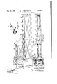
- Fig. l is a side elevation of the machine with parts broken away.
- Fig, 2 is a plan view
- Fig. 3 is a fragmentary plan view on an enlarged scale illustrating more clearly how the coagulated tube is unwound from the drum;
- Fig. 4 is an enlarged vertical longitudinal sectional view through the coagulatingtank and also showing more clearly the latex supply tank;
- Fig. 5 is a vertical transverse sectional view through the coagulating tank
- Fig. 6 is a detail broken away perspective' view showing the tubing confined externally incident to the removal of latex from the center thereof;
- Fig. 7 is a broken side View of a modified form of the apparatus showing a preliminary coagulating tank communicating with the main coagulating tank;
- Fig. 8 is a :front sectional view of an alternative device for feeding the tube of coagulated rubber dispersion transversely across the'main coagulating tank;
- Fig. 9 is a sectional view through the guid'e rod and driving screws showing the relation of the rocker arm thereto;
- Fig. 10 is a perspective view of a portion fof an elongated press which is to receive the [mold section;
- 11 is a plan View showing the alternative device for laterally moving the tube of partially coagulated rubber composition.
- the apparatus comprises a table formed of the angle bars 1 and 2 which are carried by supports 3, the supports beingI braced by rods 4.
- Receptacle 5 is rigidly affixed to the table at one end thereof and is adapted to contain coagulant for the rubber dispersiiin.
- a drum 6 of Wood or other suitable material is disposed within the receptacle, being rotatably carried upon a shaft 7 which is secured to the side walls'of the receptacle.
- the drum is submerged beneath the surface of the coagulant, which can be aqueous acetic acid or any other suitable coagulant such as a. mixture of-alcohol and acetic acid.
- the coagulant is madeY of approximately equal specific gravity to that of the rubber dispersion to be described later.
- a rubber dispersion is streamed into the coagulant from a reservoir 8 which is suspended adjacent the coagulant receptacle by a spring 9 vwhich is attached at one end to hooks 10 carried by the reservoir and is secured at the other end to a cord 11.
- Thecord passes over a pulley Wheel 12 which is secured to the ceiling of the room or to any suitable support and at its other end is woundo 5.
- rlhe delivery end of the Siphon is made of iexible tubing and a'nozzle 18 made ofD glass or other suitable material is connected thereto and opens into the coagulant.
- a cap which may be in the form of a rubber stopper or otherwise is provided to close the openin of the nozzle.
- the nozzle is preferably 0 approximately the same internal diameter as the external diameter of the tube or thread to be formed.
- a petcock 17 is provided at the top of the siphon 16 through which suction can be applied for filling the siphon without permitting retention of air bubblesy in the bend of the siphon.
- a tube 22 opens into the to of the reservoir 8 and is adapted to be use for introducing the rubber dispersion into the reservoir. signed to admit air either under atmospheric pressure or under higher or lower pressure as may be desired in conducting the rubber dispersion from the reservoir.
- a petcock provided in the top of the reservoir is adapted to be connected to a source of suction which is actuated to withdraw any bubbles of air which may be entrapped in the dispersion before the tube forming operation is begun.
- rlhe reservoir is raised or lowered as desired by the windlass 13, where by the proper hydraulic head is obtained upon the rubber dispersion.
- the spring 9 functions so that as the reservoir is emptied of its contents, the reservoir will be raised suiliciently to maintain the hydraulic head constant throughout the operation of strea1ning rubber dispersion into the kcoagulant.
- the viscosity of the material can be varied as may be deemed expedient for the size of tubing to be formed. A concentration of 55% has been found satisfactory.
- Other vulcaniziiig and compounding ingredients can be used depending upon the time and temperature of the cure and the characteristics which are desired in the completed tubing.
- Brackets 23 and ⁇ 24 (Figs. 4 and 5) extend upwardly from the receptacle 5 and carry between them a bar 25 which extends across the open top of the receptacle 5.
- a bracket 26 is slidably carried upon this bar and is provided with an arm 27 which is pivoted to the bracket and extends downwardly into the tank 5.
- a wing nut 28 provides for adjustment of the arm 27.
- a clamp 29 is pivoted upon the arm 27 and carries the nozzle 18 which extends between the arms of the clamp. Arms 21 carried by the bracket 26 serve to support the tube 16 and prevent sharp bends in the same.
- Adjustment of the wing nut 30 permits either sliding or pivotal adjustment of the nozzle 18.
- a cord or band 31 of flexible material passes through an extension of the bracket 26 and is attached thereto by means of a set screw 32.
- rlhe cord is adapted to pass under a pulley 33 which is rotatably carried upon a pin 34 which pin is secured in the bracket 24 at one side of the receptacle 5. From the pulley 33, the cord passes over one of the grooves of a cone pulley 35 which is positioned on the bracket and a. weight 36 is suspended from the free end of the cord.
- the opposite end of the cord 31 passes under a pulley 37 and over a pulley 38 which are i meunted in the bracket 237 and its free end A carries a weightk 39.
- VThe Weights provide suliicient frictional Contact between the pulley 35 and the cord to cause the cord to draw the bracket 26 along the bar 25 as the pulley is driven in a manner to be later described.
- .motor carries rigidly secured thereto a. gear .Rotation of the drum Gisetfected'by means i of a motor 40 which is supported upon a. bracket 41 which protrudes from the side of the receptacle 5.
- the drive shaft 42 of the 48. This gear meshes with a correspondinggear 44 which is rigidly mounted upon a shaft 45, the shaft being rotatably carried in a boss whichextends from the bracket 41.
- a gear 46 is secured upon one end of t-hey shaft 45 and engages with a gear 47 which is rigidly ailixed to a shaft 48, shaft 48 being rotatably mounted in a.
- a boss carried by A sprocket 55 is yrigidly mounted upon the shaft 48 and drives a chain 56 which passes around a sprocket 57 carried by the drum 6.
- An arm'() is pivotally mounted upon the inner wall of the receptacle 5 and carries rotatably at its extremity a roll 49. This roll is designed to bear against the chain 56 and take up the slack in the chain.
- a sprocket 58 is rigidly attached to the shaft 48 and carries a chain 59 which passes around a sprocket 60 carried rigidly upon the shaft 61 which latter is rotatably mounted in the bracket 24.
- Shaft 61 carries rigidly a gear 62 which is adapted to mesh with a gear 68.
- Gear 63 is rigidly affixed to a shaft 64 which is rotatably mounted in the bracket 24, and the pulley 35 over which the cord 31 passes is carried. by the shaft 64.'
- the drum 6 is rotated in a clockwise direction, as viewed in Fig. 4, and the nozzle 18 is carried across the tank at a rate of speed such that the rubber tube formed from the dispersion is Wound upon the drum in a continuous length of helical form with the turns thereof in spaced relation. Coagulation continues inwardly of the tube while the dispersion remains immersed in the coagulant.
- a sufiicient length of time has elapsed to permit the formation of a tubehaving the desired Wall thickness
- the tube is conducted from the coagulant into and through a wash tank 65.
- the wash tank is positioned adjacent the receptacle 5, being mounted upon the sup-v ports 66 which in turn rest upon the angle bars 1 and 2.
- the adjacent wall of the receptacle 5 is cut away at its outer portion a slight amount and a table 67 rests thereon and extends to and is supported by the end Wall of the .wash tank 65.
- Brackets 68 mounted on opposite sides of the wash tank serve as supports for a roll 69 mounted therebetween.
- the roll is adapted to be driven by a chain 70 which passes around the sprocket 71 rigidly attached to the shaft 72 upon which the roll is mounted.
- the chain 70 passes around a sprocket 7 3 which is carried by a shaft 74, the shaft being rotatably asprocket 77 upon the shaft 48.
- An additional guide means 79 of inverted U- shape made of glass or other suitable material is secured to the table 67 and it is designed that the length of rubber tubing shall be passed between the arms of the member 79 over the roll 69 and into the Wash tank 65.
- the Wash vtank 65 contains water or water and ammonia, into which the tubing can be submerged and the coagulant washed therefrom.
- a suitable container is comprised of the mold sections -80 and 94.
- the mold section 80 is carried upon a belt conveyor 81, the upper length of which is supported upon a plurality of rolls 82 which are carried by the angle bars 1 and 2.
- the conveyor passes over a driving roll 83 which is rigidly mounted upon the shaft 74.
- the mold can be a multiple cavity type. Receptacles other than an elongated mold are contemplated for use in receiving the tub-e at this stage of the operation such forv example as a vessel containing spiral grooves Which vessel can be revolubly mounted. The tubing can be caught in a trough if desired and the use of a mold dispensed with.
- the nozzle has the desired diameter.
- the rubber dispersion is placed in the receptacle 8.
- the Siphon is first washed with water in order to wet and thereby prevent formation of air bubbles along the walls as the dispersion is drawn into the siphon.
- the cap is placed rmly upon the nozzle of the Siphon and suction is applied to the petcock 17 drawing the rubber dispersion into the Siphon.
- a small quantity of the dispersion is drawn over through the petcock and may be caught in a trap in the suc-V tion line. This method of filling the Siphon insures that no bubbles of air will be trapped therein.
- the reservoir 8 is hoistedpby the windlass to a position such that the level of the rubber dispersion is well above the top of the coagulating tank.
- the hydraulic head of the latex is adj usted by raising or lowering the reservoir until the tubing coagulated from the stream of dispersion issuing frTolrln nozzle is adjusted so that it extends approximately parallel to the surface of the coagulant and is immersed in the liquid so that the orifice is covered with a layer of acid mixture.
- the extent to which the nozzle is tilted depends upon the specific gravity of the dispersion and the coagulant. The specific gravities are made approximately equal so that the latex will stream directly forward from the nozzle without being carried sharply upwardly or bending sharply downwardly upon the drum. This protects the tubing about itself. Meanwhile, the nozzle( tubing from having sharp folds formed in its sidewalls.
- the motor is started thereby causing rotation of the drum 6 and operation of the other parts of the machinery.
- the bracket 26 is brought to a position above one side ofthe coagulating tank 5 and the stop is removed from the nozzle 18 and drawn to the top of the drum 6, thus leading the stream of latex while coagulating to the edge of the rotating drum.
- the coagulated end of the stream is pressed firmly against the drum adhering thereto, and as the drum rotates, it winds the is carried longitudinally across the tank thereby causing the length of tubing to sety itle upon the drum in the form of a helical coil.
- the cap is replaced upon the nozzle.
- the tubing formed in this way contains a core of uncoagulated rubber dispersion which can be removed as follows:
- the mold section 80 is carried by the belt conveyor into an elongated press 95.
- This press is shown in Fig. A hydraulic or other type of press can be substituted therefor.
- the complementary mold section 94 may be carried by the upper beam of the press and, when the press is closed, section 94 rests upon the mold section 80 and is so held during the washing operation. Incisions are then made in the projectingends of the tube, and a stream of water is forced through the length of tubing, driving out the dispersion contained therein, ⁇ which treatment may be followed by injecting a current of air through the tubing thereby blowing out the residual water.
- the exit end of the tube is then sealed by pressing the walls together and air is forced through until th-e sealed end bursts.
- the tube may then be vulcanized in water. Vulcanization with the particular composition described can be effected by heating for thirty-five minutes at twenty-seven and onehalf pounds saturated steam' pressure. The vulcanized tube can then be dried in any suitable manner. Any other suitable method of vulcanization may be used or the tube may b e formed from a vulcanized rubber dispersion.
- FIGs. 8, 9 and 1l of the drawings there is illustrated a modification of the means for conducting the tube of partially coagulated rubber dispersion, formed in the preliminary coagulating tank, 110 shown in Fig. 7 longitudinally across the tank 5.
- This modification is ⁇ adaptable also for similarly conducting the nozzle 18. It comprises a guide rod 96 rigidly supported by brackets 97 above the receptacle 5 in spaced relation thereto.
- a rocker arm 98 is carried by the guide rod 96 for slidable movement thereon. The lower end ofthe rocker arm; is forkedatl99 to act as a guide for the partiallyicoagulated rubber dispersion.
- a collar 100 is carried upon j and 102.
- an elongated preliminary coagulating tank 110 which is connected with the upper portionA of the main coagulating tank 5 and is adapted to contain coagulant at the level of the coagulant in the tank 5.
- An endless string or conveyor 111 is positioned above the preliminary coagulating tank extending substantially the length thereof. It is carried upon support-- 'ing and driving rolls 112 which are connected with the source of power in any suitable Way so as to drive the conveyor at substantially the rate of speed that the periphery of the drum 6 revolves. Rubber dispersion is conducted into the coagulant at the end of the preliminaryvcoagulating tank 110 ⁇ through the nozzle 18'Wh ⁇ ichis supported by a bracket l 113.
- the outer portion of the rubber dispersion coagulates and can be manually pressed against the conveyor 111 and adheres thereto.
- the conveyor conducts the end of the tube of 4partially coagulated dispersion through the tank 110 to a position adjacent the drum 6, Whereupon the end of the tube is removed from the conveyor 111 and is pressed against and adheres tothe drum which immediately lproceeds to. wind the tube about its periphtially coagulated tube are suiiciently thick toA prevent injury to the same While being coiled upon the periphery of the drum.
- the preliminary coagulating tank is formed of considerable width and is divided into a plurality of channels by means of partitions extendlng lon ⁇ tudinally thereof.
- a nozzle, such as 18, is disposed in the outside channel which opens upon one end of the drum 6. Rubber dispersion is permitted to issue from the nozzle 18 into the coagulant contained in the channel. As the dispersion coagulates, the end thereof is manually pressed against the endless string adhering thereto and is conducted through the channel at a rate of speed suflicient to maintain the tubing straight While it is being formed. When the end of the tubing is brought to the end of the channel adjoinin the drum 6, it is removed from the string an is pressed against either the side walls of the channel or a support disposed within the channel, and adheres thereto.
- the forward end of the last mentioned tube is then preferably secured to the rear end of the first formed tube by pressingthem together and in this way a continuous length of tubing is As the chanels are emptied of their contents, additional rubber dispersion is streamed thereinto and the process of forming tubing is repeated. The coagulated tubing is 'removed from the drum 6 inthe manner previously described.
- An'extruding machine comprising a receptacle adapted to contain coagulant for a rubber dispersion, means for streaming a rubber dispersion into the coagulant below the surface of the latter, means whereby the depth and direction of .the stream may be varied, a rotary member'for winding the material in a coil as it coagulates, and means for removing the coagulated stream.
- An extruding machine comprising a receptacle adapted to contain coagulant for a rubber dispersion, means for streaming a rubber dispersion into thecoagulant, a drum for winding said stream as it coagulates, means for washing the coagulated material, and means moving in unison with said drum for removing the coagulated material from the coagulant receptacle to said washing means.
- An extruding machine comprising a receptacle adapted to contain coagulant, a vessel adaptedvto contain rubber dispersion, feeding means for passing the dispersion from the vessel into the coagulant, and means for relatively movingthevessel and the outlet of the l feeding means whereby the head ofothe body ing means fol ⁇ passingthe dispersion from the vessel into the coagulant, and t-spring means for elevating the vessel as the dispersion issues therefrom whereby the head of the body of dispersion is maintained constant. drawn around the drum 6 from the channels.
- An extruding machine comprising a receptacle adapted to contain coagulant, a vessel adapted to. contain rubber" dispersion, feeding means for passing the dispersion from theivessel into thecoagulant, means for relativel moving 'the vessel and the outlet of the feedmgmeans whereby the head of the body of dispersion is maintained constant, means for coilig the coagulated dispersion, and means for relatively moving said outlet and coiling means.
Landscapes
- Engineering & Computer Science (AREA)
- Mechanical Engineering (AREA)
- Moulding By Coating Moulds (AREA)
Description
Nov. 17, 1931. w. A. GIBBONS ET A1.
APPARATUS FOR FORMING RBBER ARTICLES 3 Sheets-Sheet l Nov. 17, 1931. w. A. GIBBONS ET AL APPARATUS FOR FORMING RUBBER ARTICLES Filed OCT.. 28. 1927 5 Sheets-Sheet 2 Nov. 17-, 1931. w. AG|BBONS ET AL APPARATUS FOR FORMING RUBBER ARTICLES Filed oct. ze, 1927 s sheets-sheet 5 mvEN-roR Wi/Z/Zs A. Gibbons .EaJdZey fa/zeLL Patented Nov. 17, 1931 uurriazo A STATES ,PATENT OFFICE WILLIS A. G-IBBON S, OF GREAT NECK', A N D EARDLEY HAZELL, OF NEW YORK, N. Y., AS- l SIGNORS TO GENERAL RUBBER COMPANY, F NEW YORK, N. Y., A CORPORATION GF NEW JERSEY APPARATUS FOR. FORMING RUBBER ARTICLES Application led October 28, 1927.- Serial No. 229,306.
der that the dispersion might be immersed inv `the coagulant a length of time suiicient to permit of the formation of coagulated rubber of the desired thickness. Variance in the force with which the dispersion issues into the c0- agulant also causes the diameter of the re.-
sulting tube to vary. Previously known devices for controlling the force have been relatively complicated and inaccurate.
lt is an object of this invention to provide for the coagulation of a stream of rubber dispersion in a small amount of space. Another object is to provide a means for maintaining a uniform pressure upon the dispersion as it streams into the coagulant. Another ob- `iect is to provide an improved method for forming tubing, thread, etc., directly `from aqueous dispersions of rubber.
In carrying out these and other objects,
latex or other dispersions of rubber which.
may or may not contain compounding ingredients and vulcanizing ingredients, is extruded at a predetermined rate of speed through a nozzle into a body of coagulant. When the stream vof ylateX strikes the coagulant the sur face thereof coagulates forming alateX filled tube which is then wound spirally upon a drinn. Coagulation continues inwardly of thel tube and when the walls of the tube have reached the desired thickness, the tube is unwound from the drum, the coagulant is washed therefrom, the core of uncoagulated dispersion is removed, and the tube is vulcanized. With a drum of suiiicient size the time required to coagulate the desired wall thickness will be less than that required to cover the drum with tubing. In this case, when the desired wallthicknessisattained,the
leading end of the tube is removed from the drum and started through the rest of the apparatus while the streaming of the dispersion is continued until the drum has been completely covered.
A preferred form of apparatus by which the invention can be carried out, is shown in the accompanying drawings, in which:
Fig. l is a side elevation of the machine with parts broken away.
Fig, 2 is a plan view;
Fig. 3 is a fragmentary plan view on an enlarged scale illustrating more clearly how the coagulated tube is unwound from the drum;
Fig. 4 is an enlarged vertical longitudinal sectional view through the coagulatingtank and also showing more clearly the latex supply tank;
Fig. 5 is a vertical transverse sectional view through the coagulating tank;
Fig. 6 is a detail broken away perspective' view showing the tubing confined externally incident to the removal of latex from the center thereof;
Fig. 7 is a broken side View of a modified form of the apparatus showing a preliminary coagulating tank communicating with the main coagulating tank;
Fig. 8 is a :front sectional view of an alternative device for feeding the tube of coagulated rubber dispersion transversely across the'main coagulating tank;
Fig. 9 is a sectional view through the guid'e rod and driving screws showing the relation of the rocker arm thereto;
Fig. 10 is a perspective view of a portion fof an elongated press which is to receive the [mold section; and
11 is a plan View showing the alternative device for laterally moving the tube of partially coagulated rubber composition.
Referring particularly to the drawings. the apparatus comprises a table formed of the angle bars 1 and 2 which are carried by supports 3, the supports beingI braced by rods 4. Receptacle 5 is rigidly affixed to the table at one end thereof and is adapted to contain coagulant for the rubber dispersiiin.
A drum 6 of Wood or other suitable material is disposed within the receptacle, being rotatably carried upon a shaft 7 which is secured to the side walls'of the receptacle. The drum is submerged beneath the surface of the coagulant, which can be aqueous acetic acid or any other suitable coagulant such as a. mixture of-alcohol and acetic acid. The coagulant is madeY of approximately equal specific gravity to that of the rubber dispersion to be described later.
A rubber dispersion is streamed into the coagulant from a reservoir 8 which is suspended adjacent the coagulant receptacle by a spring 9 vwhich is attached at one end to hooks 10 carried by the reservoir and is secured at the other end to a cord 11. Thecord passes over a pulley Wheel 12 which is secured to the ceiling of the room or to any suitable support and at its other end is woundo 5. rlhe delivery end of the Siphon is made of iexible tubing and a'nozzle 18 made ofD glass or other suitable material is connected thereto and opens into the coagulant. A cap which may be in the form of a rubber stopper or otherwise is provided to close the openin of the nozzle. The nozzle is preferably 0 approximately the same internal diameter as the external diameter of the tube or thread to be formed. A petcock 17 is provided at the top of the siphon 16 through which suction can be applied for filling the siphon without permitting retention of air bubblesy in the bend of the siphon. A tube 22 opens into the to of the reservoir 8 and is adapted to be use for introducing the rubber dispersion into the reservoir. signed to admit air either under atmospheric pressure or under higher or lower pressure as may be desired in conducting the rubber dispersion from the reservoir. A petcock provided in the top of the reservoir is adapted to be connected to a source of suction which is actuated to withdraw any bubbles of air which may be entrapped in the dispersion before the tube forming operation is begun. rlhe reservoir is raised or lowered as desired by the windlass 13, where by the proper hydraulic head is obtained upon the rubber dispersion. The spring 9 functions so that as the reservoir is emptied of its contents, the reservoir will be raised suiliciently to maintain the hydraulic head constant throughout the operation of strea1ning rubber dispersion into the kcoagulant.
It is also dey Parts by weight Rubber ('as 60% latex) 100 Sulphur (precipitated) 2.7
Heptaldehyde aniline condensation product 5 Zinc oxide 2 Glue 2 The viscosity of the material can be varied as may be deemed expedient for the size of tubing to be formed. A concentration of 55% has been found satisfactory. Other vulcaniziiig and compounding ingredients can be used depending upon the time and temperature of the cure and the characteristics which are desired in the completed tubing.
Apparatus is provided for conducting the nozzle 18 laterally through the tank as the dispersion is streamed therefrom. Brackets 23 and`24 (Figs. 4 and 5) extend upwardly from the receptacle 5 and carry between them a bar 25 which extends across the open top of the receptacle 5. A bracket 26 is slidably carried upon this bar and is provided with an arm 27 which is pivoted to the bracket and extends downwardly into the tank 5. A wing nut 28 provides for adjustment of the arm 27. A clamp 29 is pivoted upon the arm 27 and carries the nozzle 18 which extends between the arms of the clamp. Arms 21 carried by the bracket 26 serve to support the tube 16 and prevent sharp bends in the same. Adjustment of the wing nut 30 permits either sliding or pivotal adjustment of the nozzle 18. A cord or band 31 of flexible material passes through an extension of the bracket 26 and is attached thereto by means of a set screw 32. rlhe cord is adapted to pass under a pulley 33 which is rotatably carried upon a pin 34 which pin is secured in the bracket 24 at one side of the receptacle 5. From the pulley 33, the cord passes over one of the grooves of a cone pulley 35 which is positioned on the bracket and a. weight 36 is suspended from the free end of the cord. The opposite end of the cord 31 passes under a pulley 37 and over a pulley 38 which are i meunted in the bracket 237 and its free end A carries a weightk 39. VThe Weights provide suliicient frictional Contact between the pulley 35 and the cord to cause the cord to draw the bracket 26 along the bar 25 as the pulley is driven in a manner to be later described.
, the bracket 41.
.motor carries rigidly secured thereto a. gear .Rotation of the drum Gisetfected'by means i of a motor 40 which is supported upon a. bracket 41 which protrudes from the side of the receptacle 5. The drive shaft 42 of the 48. This gear meshes with a correspondinggear 44 which is rigidly mounted upon a shaft 45, the shaft being rotatably carried in a boss whichextends from the bracket 41. A gear 46 is secured upon one end of t-hey shaft 45 and engages with a gear 47 which is rigidly ailixed to a shaft 48, shaft 48 being rotatably mounted in a. boss carried by A sprocket 55 is yrigidly mounted upon the shaft 48 and drives a chain 56 which passes around a sprocket 57 carried by the drum 6. An arm'() is pivotally mounted upon the inner wall of the receptacle 5 and carries rotatably at its extremity a roll 49. This roll is designed to bear against the chain 56 and take up the slack in the chain.
During rotation of thedrum 6, the nozzle 18 is drawn laterally across the face thereof. Driving power is transmitted from the shaft 48 as follows: A sprocket 58 is rigidly attached to the shaft 48 and carries a chain 59 which passes around a sprocket 60 carried rigidly upon the shaft 61 which latter is rotatably mounted in the bracket 24. Shaft 61 carries rigidly a gear 62 which is adapted to mesh with a gear 68. Gear 63 is rigidly affixed to a shaft 64 which is rotatably mounted in the bracket 24, and the pulley 35 over which the cord 31 passes is carried. by the shaft 64.'
By the mechanism described, the drum 6 is rotated in a clockwise direction, as viewed in Fig. 4, and the nozzle 18 is carried across the tank at a rate of speed such that the rubber tube formed from the dispersion is Wound upon the drum in a continuous length of helical form with the turns thereof in spaced relation. Coagulation continues inwardly of the tube while the dispersion remains immersed in the coagulant. When .a sufiicient length of time has elapsed to permit the formation of a tubehaving the desired Wall thickness, the tube is conducted from the coagulant into and through a wash tank 65. The wash tank is positioned adjacent the receptacle 5, being mounted upon the sup-v ports 66 which in turn rest upon the angle bars 1 and 2. The adjacent wall of the receptacle 5 is cut away at its outer portion a slight amount and a table 67 rests thereon and extends to and is supported by the end Wall of the .wash tank 65. Brackets 68 mounted on opposite sides of the wash tank serve as supports for a roll 69 mounted therebetween. The roll is adapted to be driven by a chain 70 which passes around the sprocket 71 rigidly attached to the shaft 72 upon which the roll is mounted. The chain 70 passes around a sprocket 7 3 which is carried by a shaft 74, the shaft being rotatably asprocket 77 upon the shaft 48.
supported'fby-the angle bars 1 and 2. The shaft'isdriven by `a Achain 75 which passes around a sprocket 76 on shaft 74 and around guide rod 78 made of glass or other suitablemate`rial is suitably positioned so as to serve-as a'support for the length of tubing as it is conducted from the receptacle 5. An additional guide means 79 of inverted U- shape made of glass or other suitable material is secured to the table 67 and it is designed that the length of rubber tubing shall be passed between the arms of the member 79 over the roll 69 and into the Wash tank 65.' The Wash vtank 65 contains water or water and ammonia, into which the tubing can be submerged and the coagulant washed therefrom.
After the length of'rubber tubing has been Washed to remove coagulant from the same, it is removed from the Wash tank to a container in which it can be suitably held While the core of uncoagulated rubber dispersion is being removed. A suitable container is comprised of the mold sections -80 and 94. The mold section 80 is carried upon a belt conveyor 81, the upper length of which is supported upon a plurality of rolls 82 which are carried by the angle bars 1 and 2. The conveyor passes over a driving roll 83 which is rigidly mounted upon the shaft 74. The
opposite end of the conveyor passes around the roll 84. The rate of travel of the conveyor is so timed that the mold section 80 will be passed along at the same rate at which the. length of rubber tubing is delivered thereto. The tubing is conducted to the mold by means of a belt conveyor 85 whichJ passes around a drive roll 86 which is rotatably mounted on shaft 54 between a pair of supa sprocket 93 rigidly secured to the shaft 72.
Sufficient space is left between the roll 88 and the belt 81 so that 'the mold section can be passed therebetween. Upon positioning of the length of the rubber tubing in the mold section 80, the corresponding mold section 94 is applied thereto. The mold can be a multiple cavity type. Receptacles other than an elongated mold are contemplated for use in receiving the tub-e at this stage of the operation such forv example as a vessel containing spiral grooves Which vessel can be revolubly mounted. The tubing can be caught in a trough if desired and the use of a mold dispensed with.
In utilizing the apparatus described, the
' the nozzle has the desired diameter.
rubber dispersion is placed in the receptacle 8. The Siphon is first washed with water in order to wet and thereby prevent formation of air bubbles along the walls as the dispersion is drawn into the siphon. The cap is placed rmly upon the nozzle of the Siphon and suction is applied to the petcock 17 drawing the rubber dispersion into the Siphon. After filling the siphon a small quantity of the dispersion is drawn over through the petcock and may be caught in a trap in the suc-V tion line. This method of filling the Siphon insures that no bubbles of air will be trapped therein. The reservoir 8 is hoistedpby the windlass to a position such that the level of the rubber dispersion is well above the top of the coagulating tank. The hydraulic head of the latex is adj usted by raising or lowering the reservoir until the tubing coagulated from the stream of dispersion issuing frTolrln nozzle is adjusted so that it extends approximately parallel to the surface of the coagulant and is immersed in the liquid so that the orifice is covered with a layer of acid mixture. The extent to which the nozzle is tilted depends upon the specific gravity of the dispersion and the coagulant. The specific gravities are made approximately equal so that the latex will stream directly forward from the nozzle without being carried sharply upwardly or bending sharply downwardly upon the drum. This protects the tubing about itself. Meanwhile, the nozzle( tubing from having sharp folds formed in its sidewalls.
. The motor is started thereby causing rotation of the drum 6 and operation of the other parts of the machinery.. The bracket 26 is brought to a position above one side ofthe coagulating tank 5 and the stop is removed from the nozzle 18 and drawn to the top of the drum 6, thus leading the stream of latex while coagulating to the edge of the rotating drum. The coagulated end of the stream is pressed firmly against the drum adhering thereto, and as the drum rotates, it winds the is carried longitudinally across the tank thereby causing the length of tubing to sety itle upon the drum in the form of a helical coil. When the available space upon the .drumu has been covered with tubing, the cap ,is replaced upon the nozzle. The time at which the dispersion first began to stream intol the' coagulant having been noted the resulting tubing is maintained in the coagulant until suflicient time has elapsed for the tube to have gained the desired wall thickness by action of the coagulant. Thereupon the first formed end of the tube is pulled away from the drum, passed over the glass rod 7 8 between the arms of the U-shape member' 7 9 and over the roll 69 into and through thewash tank and is placed upon the belt .conveyor 85. The operation of removing the 10 as ahand press.
'is severed into lengths slightly longer than the length of the mold and the walls of the ends are pressed together. This occurs usually as a result of the severing action.
The tubing formed in this way contains a core of uncoagulated rubber dispersion which can be removed as follows: The mold section 80 is carried by the belt conveyor into an elongated press 95. This press is shown in Fig. A hydraulic or other type of press can be substituted therefor. The complementary mold section 94 may be carried by the upper beam of the press and, when the press is closed, section 94 rests upon the mold section 80 and is so held during the washing operation. Incisions are then made in the projectingends of the tube, and a stream of water is forced through the length of tubing, driving out the dispersion contained therein, `which treatment may be followed by injecting a current of air through the tubing thereby blowing out the residual water. The exit end of the tube is then sealed by pressing the walls together and air is forced through until th-e sealed end bursts.
.This procedure causes the tube to swell and fill the mold uniformly, thereby .removing any defects which may have been incurred through handling. In case of large size tubing where loss of rubber dispersion would be considerable, the latter is recovered by iirst displacing it with air, collecting it separately, and then washing out the residue in the tubef by a stream of water. If a solid thread is made, these steps are not necessary. The tube may then be vulcanized in water. Vulcanization with the particular composition described can be effected by heating for thirty-five minutes at twenty-seven and onehalf pounds saturated steam' pressure. The vulcanized tube can then be dried in any suitable manner. Any other suitable method of vulcanization may be used or the tube may b e formed from a vulcanized rubber dispersion.
In Figs. 8, 9 and 1l of the drawings there is illustrated a modification of the means for conducting the tube of partially coagulated rubber dispersion, formed in the preliminary coagulating tank, 110 shown in Fig. 7 longitudinally across the tank 5. This modification is `adaptable also for similarly conducting the nozzle 18. It comprises a guide rod 96 rigidly supported by brackets 97 above the receptacle 5 in spaced relation thereto. A rocker arm 98 is carried by the guide rod 96 for slidable movement thereon. The lower end ofthe rocker arm; is forkedatl99 to act as a guide for the partiallyicoagulated rubber dispersion. A collar 100 is carried upon j and 102. These grooved portions'are adapty-ed to alternately engage two screw rods 103 and 104 which extend longitudinally across the receptacle 5 in spaced relation thereto and are mounted for rotary movement in the brackets 97. The rods '103 and 104 carry gears 105 and 106 respectively Which interengage, and gear 106 is'driven by the. motor 107 through,v the pinion 108. The rods are positioned .upon opposite sides of the rocker arm 98 so that upon inclination o'f the rocker armto one side, it will engage the threads of one of the rods and be driven longitudinally across the receptacle 5 in 'one direction. Up-
on"inelination of theerocker arm 98 in the opposite `direction, it bears against and is driven by the other rod in the reverse direction across the receptacle 5 to a position ready to conduct-a fresh tube laterally across the receptacle. The upper end ofthe rocker arm 98 carries a Weight 109 to insure positive engagement of the rocker arm with the screw rods. The speedof rotation of the rods 103 and 104 is such that the rocker arm 98 is moved laterally across vthe receptacle 5 at a rate of speed to cause the tube of partially coagulated rubber composition to be Wound upon the periphery of the drum in spaced spirals. This feed is positive in its action and causes a smooth continuous lateral feed of the rocker arm.
In the modification of the device illustrated in Fig. 7, there is provided an elongated preliminary coagulating tank 110 which is connected with the upper portionA of the main coagulating tank 5 and is adapted to contain coagulant at the level of the coagulant in the tank 5. An endless string or conveyor 111 is positioned above the preliminary coagulating tank extending substantially the length thereof. It is carried upon support-- 'ing and driving rolls 112 which are connected with the source of power in any suitable Way so as to drive the conveyor at substantially the rate of speed that the periphery of the drum 6 revolves. Rubber dispersion is conducted into the coagulant at the end of the preliminaryvcoagulating tank 110 `through the nozzle 18'Wh`ichis supported by a bracket l 113. As it issues'from the nozzle 18, the outer portion of the rubber dispersion coagulates and can be manually pressed against the conveyor 111 and adheres thereto. The conveyor conducts the end of the tube of 4partially coagulated dispersion through the tank 110 to a position adjacent the drum 6, Whereupon the end of the tube is removed from the conveyor 111 and is pressed against and adheres tothe drum which immediately lproceeds to. wind the tube about its periphtially coagulated tube are suiiciently thick toA prevent injury to the same While being coiled upon the periphery of the drum.
When large size tubing is to be made, such as for example tubing having a diameter'of one half inch or more, it is necessary that the partially formed tube be maintained in a. still body of coagulant for a prolon ed period of time in order that side walls may e formed of a suicient thickness to permit of disposing the tube in a coil upon the surface of the drum 6 without injury to the partially formed tube. This result is preferably attained by the following arrangement of parts. The preliminary coagulating tank is formed of considerable width and is divided into a plurality of channels by means of partitions extendlng lon `tudinally thereof. The partieach channel and is driven in travel in the manner described in connection with conveyor 111. A nozzle, such as 18, is disposed in the outside channel which opens upon one end of the drum 6. Rubber dispersion is permitted to issue from the nozzle 18 into the coagulant contained in the channel. As the dispersion coagulates, the end thereof is manually pressed against the endless string adhering thereto and is conducted through the channel at a rate of speed suflicient to maintain the tubing straight While it is being formed. When the end of the tubing is brought to the end of the channel adjoinin the drum 6, it is removed from the string an is pressed against either the side walls of the channel or a support disposed within the channel, and adheres thereto. At the same time, the flow of rubber dispersion from the nozzle 18 is discontinued and the rear end of the partially formed tube is disconnected y.therefrom and is caused to adhere to either lowed to proceed in the first formed tube.' until it has side walls of sufficient strength so that the tube can be wound upon the drum 6 without bursting or collapsing. When .this has been accomplished the ends of-the tube are loosened from their supports.and the forward end is` pressed against and caused to adhere to the drum 6. -The tube is now wound around the drum 6 in the manner previously described". The operation is preferably so coordinatedv that at the time that the rear end of tlietube passes from the. channel, the next adjoining tube has reached the desired degree of strength. The forward end of the last mentioned tube is then preferably secured to the rear end of the first formed tube by pressingthem together and in this way a continuous length of tubing is As the chanels are emptied of their contents, additional rubber dispersion is streamed thereinto and the process of forming tubing is repeated. The coagulated tubing is 'removed from the drum 6 inthe manner previously described.
.J While in the apparatus described, .a single drum-has been used, it is contemplated (to mount two or more drums adjacent each other and to remove the tube from'one drum while a new tube is being formed on the other drum. Other driving'means, such as a chain or belt, can/bersubstituted forthe cord 31. It is also ...contemplated to provide the surface of the drum with a spiral groove into which the tube will be seated as it is formed. Other modifications will suggest themselves to those skilled in theart.
Having thus described our invention, what we claim and desire to protect by Letters Patent is:
1. An'extruding machine comprising a receptacle adapted to contain coagulant for a rubber dispersion, means for streaming a rubber dispersion into the coagulant below the surface of the latter, means whereby the depth and direction of .the stream may be varied, a rotary member'for winding the material in a coil as it coagulates, and means for removing the coagulated stream.
2. An extruding machine comprising a receptacle adapted to contain coagulant for a rubber dispersion, means for streaming a rubber dispersion into thecoagulant, a drum for winding said stream as it coagulates, means for washing the coagulated material, and means moving in unison with said drum for removing the coagulated material from the coagulant receptacle to said washing means. v
3. An extruding machine comprising a receptacle adapted to contain coagulant, a vessel adaptedvto contain rubber dispersion, feeding means for passing the dispersion from the vessel into the coagulant, and means for relatively movingthevessel and the outlet of the l feeding means whereby the head ofothe body ing means fol` passingthe dispersion from the vessel into the coagulant, and t-spring means for elevating the vessel as the dispersion issues therefrom whereby the head of the body of dispersion is maintained constant. drawn around the drum 6 from the channels.
6. An extruding machine comprising a receptacle adapted to contain coagulant, a vessel adapted to. contain rubber" dispersion, feeding means for passing the dispersion from theivessel into thecoagulant, means for relativel moving 'the vessel and the outlet of the feedmgmeans whereby the head of the body of dispersion is maintained constant, means for coilig the coagulated dispersion, and means for relatively moving said outlet and coiling means.
Signed at New York, New York, this 21st day of October, 1927.0
WILLIS A. GIBBONS. Signed at New York, New York, this 21st day of October, 1927 EARDLEY HAZELL.
Priority Applications (1)
| Application Number | Priority Date | Filing Date | Title |
|---|---|---|---|
| US229306A US1832012A (en) | 1927-10-28 | 1927-10-28 | Apparatus for forming rubber articles |
Applications Claiming Priority (1)
| Application Number | Priority Date | Filing Date | Title |
|---|---|---|---|
| US229306A US1832012A (en) | 1927-10-28 | 1927-10-28 | Apparatus for forming rubber articles |
Publications (1)
| Publication Number | Publication Date |
|---|---|
| US1832012A true US1832012A (en) | 1931-11-17 |
Family
ID=22860653
Family Applications (1)
| Application Number | Title | Priority Date | Filing Date |
|---|---|---|---|
| US229306A Expired - Lifetime US1832012A (en) | 1927-10-28 | 1927-10-28 | Apparatus for forming rubber articles |
Country Status (1)
| Country | Link |
|---|---|
| US (1) | US1832012A (en) |
-
1927
- 1927-10-28 US US229306A patent/US1832012A/en not_active Expired - Lifetime
Similar Documents
| Publication | Publication Date | Title |
|---|---|---|
| US2256190A (en) | Method of handling chewing gum | |
| US3115668A (en) | Machine for encasing sausage and the like | |
| US1601686A (en) | Sausage casing | |
| US2489503A (en) | Machine for making tubing | |
| US1832012A (en) | Apparatus for forming rubber articles | |
| US2630598A (en) | Sausage skinning mechanism | |
| US1977515A (en) | Machine for extruding plastic materials | |
| US2686927A (en) | Sausage skinning mechanism | |
| US1879882A (en) | Wreath making method and means | |
| US1643999A (en) | Method and apparatus for making tubes | |
| US2209726A (en) | Irrigation tile making machine | |
| US2200735A (en) | Continuous vulcanizing apparatus | |
| US2187790A (en) | Apparatus for measuring intestines | |
| US2006375A (en) | Method of and apparatus for forming enwrapped bars of a comestible or plastic material | |
| US1990481A (en) | Tube making machine | |
| US1724354A (en) | Method of and apparatus for constructing inner tubes for tires | |
| US1852831A (en) | Tube trimming method and apparatus | |
| US775542A (en) | Apparatus for molding plastic materials. | |
| US2764218A (en) | Apparatus for coating and reinforcing pipe | |
| US2895165A (en) | Radius bar linkage | |
| US2241856A (en) | Manufacture of rubber thread or the like | |
| CN107718505A (en) | A kind of plastics material-extruding machine with high-efficiency heating function | |
| CN208896485U (en) | A kind of production equipment of plastic foil | |
| US2781988A (en) | Winding machine for link sausage | |
| US2284520A (en) | Process and apparatus for producing rubber articles |