US1831663A - Lunch kit - Google Patents
Lunch kit Download PDFInfo
- Publication number
- US1831663A US1831663A US387721A US38772129A US1831663A US 1831663 A US1831663 A US 1831663A US 387721 A US387721 A US 387721A US 38772129 A US38772129 A US 38772129A US 1831663 A US1831663 A US 1831663A
- Authority
- US
- United States
- Prior art keywords
- container
- casing
- cushions
- cover member
- kit
- Prior art date
- Legal status (The legal status is an assumption and is not a legal conclusion. Google has not performed a legal analysis and makes no representation as to the accuracy of the status listed.)
- Expired - Lifetime
Links
- 239000000463 material Substances 0.000 description 5
- 238000010276 construction Methods 0.000 description 4
- 239000007799 cork Substances 0.000 description 4
- 239000011521 glass Substances 0.000 description 4
- 238000009413 insulation Methods 0.000 description 3
- ATJFFYVFTNAWJD-UHFFFAOYSA-N Tin Chemical compound [Sn] ATJFFYVFTNAWJD-UHFFFAOYSA-N 0.000 description 2
- 238000003475 lamination Methods 0.000 description 2
- 238000005192 partition Methods 0.000 description 2
- 230000015572 biosynthetic process Effects 0.000 description 1
- 238000004140 cleaning Methods 0.000 description 1
- 235000021270 cold food Nutrition 0.000 description 1
- 150000001875 compounds Chemical class 0.000 description 1
- 235000021268 hot food Nutrition 0.000 description 1
- 239000010985 leather Substances 0.000 description 1
- 238000012423 maintenance Methods 0.000 description 1
- 239000002184 metal Substances 0.000 description 1
- 230000004048 modification Effects 0.000 description 1
- 238000012986 modification Methods 0.000 description 1
- 230000002035 prolonged effect Effects 0.000 description 1
Images

Classifications
-
- A—HUMAN NECESSITIES
- A45—HAND OR TRAVELLING ARTICLES
- A45C—PURSES; LUGGAGE; HAND CARRIED BAGS
- A45C11/00—Receptacles for purposes not provided for in groups A45C1/00-A45C9/00
- A45C11/20—Lunch or picnic boxes or the like
Definitions
- a further object of the invention is to provide a device of this kind which comprises throughout its structure the use of cushions of cork, rubber, and kindred material, which serve to substantially eliminate breakage.
- the invention consists in the details of construction and in the combination and arrangement of the several parts of my improved lunch kit whereby certain important advantages are attained and the device rendered simpler, less expensive and otherwise more convenient and advantageous for use, as will be hereinafter more fully set forth.
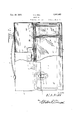
- Figure 1 is a view partly in side elevation and partly in section of a lunch kit constructed in accordance with an embodiment of my invention
- Figure 2 is an end View partly in elevation 45 and partly in section of the device as illustrated in Figure 1;
- Figure 3 is a fragmentary detailed sectional view on an enlarged scale taken substantially on the line 33 of Figure 1 looking in the direction of the arrow
- Figure 4 is-a fra mentary detailed sectional view taken su stantially on the line H of Figure 2;
- Figure 5 is a sectional view taken substantially on the line 55 of Figure 4.
- 1 denotes a cover preferably of tin of des red configuration and dimensions and which has arranged centrally thereof and secured to its upper portion a transversely disposed holding member 2.
- This member 2 is in the form of an inverted U and ossesses a certain degree of resiliency. Ad acent to its opposite ends the upper portion of the top 1 has secured thereto the loop brackets 3 throu h which are engaged the end portions of a handle strap 4:, preferably of leather.
- One end portion of the member 2 has hingedly connected thereto, as at 5, an end portion of an elongated spring member 6.
- this spring 6 is provided with an opening 7 through which .is adapted to be directed a reduced extension ber 2, sa (1 extension 8 having an opening 9 through hich is adapted to be projected a lug 10 carried by the spring 6 and extend-. ing inwardly of the opening 7 As particularly illustrated in Figure 2, it
- the spring 6 ca-rrieiry the adjacent end of the memis to be noted that the spring 6 is disposed lengthwise on a compound curvature afiording a relatively large central depending portion.
- the top 1 has its lower free marginal portions defined by the skirts 11 and each of said side skirts adjacent each end has fixed thereto a projected lug 12.
- This casing C is made 0 metal or any other desired material, and the upper portion of each of its side faces adjacent each end thereof has pivotally connected therewith a finger piece 14.
- This finger piece 14 has operatively connected therewith a rigid loop 15.
- a g ass container G Arranged within the casin C is a g ass container G, the walls of w ich being of double construction affording an intermediate vacuum space 16 giving an effective insulation against heat and thereby assuring the maintenance of the temperature of the articles placed within the container for a prolonged period of time.
- the container G is divided mto t wo compartments by the transverse partition P, it being understood, however, that other of such compartments may be aflforded by use of additional partitions.
- the applied container G is rested directly upon the longitudinally disposed cushions 18 carried by the bottom wall 19 of the casmg C, and interposed between the side walls of the container G and of the casing C at the lower portions thereof are the cushion strips 20.
- These cushion strips 18 and 20 may be of rubber, cork or other suitable material which will serve as an effective medium to substantially eliminate the liability of breakage of the container G.
- the upper portion of the container G has extending outwardly from its walls a shoulder 21 and in contact with this shoulder 21 and the portions of said side walls of the container G thereabove are the cushion strips 22 of rubber or other suitable material. Each of these strips 22 is directly carried by the upper marginal portion of the adjacent side wall of the casing G as particularly illustrated in detailed Figure 3.
- each of the side walls of the container G is provided with a groove 23 to receive and retain a gasket 24 preferably of rubber.
- the upper open face of the container G 18 adapted to be closed by a cover member M.
- This member embodies a lower plate 26 of glass having a central vacuum space 27 and each marginal portion of this plate- 26 in its under surface has a groove 28 to receive a gasket 24 when the cover member M is in applied or working position, thus providing an effective seal against the outside temperature.
- a lamination 29 of ground cork Disposed over the glass plate 26 is a lamination 29 of ground cork, the same being maintained in desired placement with respect to the late 26 by the retaining cover 31 preferab ly of tin.
- the marginal portions of this cover 31 are engaged from below with the marginal portions of the plate 26 and interposed between the marginal faces of the glass plate 26 and the adjacent walls of the cover 31 are the cushions 32, preferably of soft rubber, which serve effectually to prevent breakage of the plate 26.
- the central portion of the cover 31 is provided with a pair of upstanding and longitudinally aligned sleeves or barrels 33 with which are engaged the extremities of a loop handle 34, said handle 34 providing means for effectively manipulating the cover member M.
- the top 1 above but in relativel close proximity to its skirts 11 has seoured thereto the cushions 35, preferably of soft rubber, and Which have firm contact from above with the adjacent marginal portions of the applied cover member M and thereby affording additional effective means for maintaining the cover member M applied.
- the lamination 29 of cork hereinbefore referred to serves as a further means of insulation it also provides an elfective medium to protect the glass plate 26 against breakage.
- any portion of the container G should break, it may be removed by crushing the remaining portion of such container and the parts removed. After such removal a new container can be readily applied with a minimum of effort and labor.
- kits constructed in accord! ance with my invention the materials placed therein may be maintained for a protracted period of time at desired temperature and this applies with equal facility in connection with either cold foods or hot foods.
- top 1 is of such cross sectional configuration to readily permit the application therein of a conventional vacuum bottle which will be readily maintained therein by the spring 6.
- a kit of the class described comprising a casing, a container arranged within the casing, said container havin its walls of double construction to provi e vacuum insulation, cushions interposed between the bottoms of the casing and the container, cushions interposed between the lower portions of the side walls of the casing and the container, and cushions carried by the upper portions of the side walls of the casing for contact with the adjacent portions of the container, said casin having inwardly extending flanges for holding said cushions in adjusted position the side walls of the container being provided with outstanding shoulders engagmg said last named cushions from below.
- kits of the class described comprising able over the lugs,
- a casing a container placed therein, cushions interposed between the bottom walls and side walls of the container and casing, a fiat cover member for the container, a top adapted to be disposed over the applied cover member and la ping the container, internal cushions carried by the top for contact with the applied cover member from above and on the marginal edges thereof, and means for locking the cover member to the casing.
- a kit of the class described comprising a casing, a container placed therein, cushions interposed between the bottom walls and side walls of the container and easing, a flat cover member for the container, a top adapted to be disposed over the applied cover member and lapping the container, internal cushions carried by the top for contact with the applied cover member from above and on the marginal edges thereof, outstanding lugs carried by the portions of the top lapping the casing, finger pieces pivoted to side walls of the casing, and loop members operatively engaged with the finger pieces and engageswinging movement of the finger pieces towards the casing exerting pull on the top when the members are engaged with the lugs where y to hold the top in tight engagement with the container.
Landscapes
- Purses, Travelling Bags, Baskets, Or Suitcases (AREA)
Description
Nov. 10, 1931.
H. L. HILL LUNCH KIT Filed Aug. 22. 1929 2 Sheets-Sheet l H. L. HILL Nov. 10, 1931.
LUNCH KI T Filed Aug. 22. 1929 2 Sheets-Sheet 2 Patented Nov. 10, 1931 PATENT OFFICE nowaan L. HILL, or mm, CALIFORNIA.
LUNCH KIT Application filed August 22, 1929. Serial No. 387,721.
sociated a removable top or cover member,
said assembly making it practical for the consumer to eat from the container itself.
Furthermore, it is an object of the invention to provide a device of this kind of what might be termed open construction so that the various parts are readily accessible for cleaning and thus maintaining the devlce sanitary.
A further object of the invention is to provide a device of this kind which comprises throughout its structure the use of cushions of cork, rubber, and kindred material, which serve to substantially eliminate breakage.
The invention consists in the details of construction and in the combination and arrangement of the several parts of my improved lunch kit whereby certain important advantages are attained and the device rendered simpler, less expensive and otherwise more convenient and advantageous for use, as will be hereinafter more fully set forth.
The novel features of my invention will hereinafter be definitely claimed.
In order that my invention may be the better understood, I will now proceed to describe the same with reference to the accompanying drawings, wherein Figure 1 is a view partly in side elevation and partly in section of a lunch kit constructed in accordance with an embodiment of my invention;
Figure 2 is an end View partly in elevation 45 and partly in section of the device as illustrated in Figure 1;
Figure 3 is a fragmentary detailed sectional view on an enlarged scale taken substantially on the line 33 of Figure 1 looking in the direction of the arrow Figure 4 is-a fra mentary detailed sectional view taken su stantially on the line H of Figure 2;
Figure 5 is a sectional view taken substantially on the line 55 of Figure 4.
As disclosed in the accompanying drawlngs, 1 denotes a cover preferably of tin of des red configuration and dimensions and which has arranged centrally thereof and secured to its upper portion a transversely disposed holding member 2. This member 2 is in the form of an inverted U and ossesses a certain degree of resiliency. Ad acent to its opposite ends the upper portion of the top 1 has secured thereto the loop brackets 3 throu h which are engaged the end portions of a handle strap 4:, preferably of leather. One end portion of the member 2 has hingedly connected thereto, as at 5, an end portion of an elongated spring member 6.
The opposite end portion of this spring 6 is provided with an opening 7 through which .is adapted to be directed a reduced extension ber 2, sa (1 extension 8 having an opening 9 through hich is adapted to be projected a lug 10 carried by the spring 6 and extend-. ing inwardly of the opening 7 As particularly illustrated in Figure 2, it
8 ca-rrieiry the adjacent end of the memis to be noted that the spring 6 is disposed lengthwise on a compound curvature afiording a relatively large central depending portion.
The top 1 has its lower free marginal portions defined by the skirts 11 and each of said side skirts adjacent each end has fixed thereto a projected lug 12. When in applied position the skirts ll of the top 1 overlap the u per marginal portions of the outer casing of the body proper of the kit. This casing C is made 0 metal or any other desired material, and the upper portion of each of its side faces adjacent each end thereof has pivotally connected therewith a finger piece 14. This finger piece 14 has operatively connected therewith a rigid loop 15. By engaging the loop 15 over a lug or projection 12 and swinging the finger piece 14 downwardly, means are provided for eflectively maintalning the top 1 in applied or working position with respect to the casing C, yet at the same time affording a mechanism which ermits the ready and convenient removal 0 said to 1.
Arranged within the casin C is a g ass container G, the walls of w ich being of double construction affording an intermediate vacuum space 16 giving an effective insulation against heat and thereby assuring the maintenance of the temperature of the articles placed within the container for a prolonged period of time. As herein disclosed, the container G is divided mto t wo compartments by the transverse partition P, it being understood, however, that other of such compartments may be aflforded by use of additional partitions.
The applied container G is rested directly upon the longitudinally disposed cushions 18 carried by the bottom wall 19 of the casmg C, and interposed between the side walls of the container G and of the casing C at the lower portions thereof are the cushion strips 20. These cushion strips 18 and 20 may be of rubber, cork or other suitable material which will serve as an effective medium to substantially eliminate the liability of breakage of the container G.
The upper portion of the container G has extending outwardly from its walls a shoulder 21 and in contact with this shoulder 21 and the portions of said side walls of the container G thereabove are the cushion strips 22 of rubber or other suitable material. Each of these strips 22 is directly carried by the upper marginal portion of the adjacent side wall of the casing G as particularly illustrated in detailed Figure 3.
The top edge face of each of the side walls of the container G is provided with a groove 23 to receive and retain a gasket 24 preferably of rubber.
The upper open face of the container G 18 adapted to be closed by a cover member M. This member embodies a lower plate 26 of glass having a central vacuum space 27 and each marginal portion of this plate- 26 in its under surface has a groove 28 to receive a gasket 24 when the cover member M is in applied or working position, thus providing an effective seal against the outside temperature.
Disposed over the glass plate 26 is a lamination 29 of ground cork, the same being maintained in desired placement with respect to the late 26 by the retaining cover 31 preferab ly of tin. The marginal portions of this cover 31 are engaged from below with the marginal portions of the plate 26 and interposed between the marginal faces of the glass plate 26 and the adjacent walls of the cover 31 are the cushions 32, preferably of soft rubber, which serve effectually to prevent breakage of the plate 26. The central portion of the cover 31 is provided with a pair of upstanding and longitudinally aligned sleeves or barrels 33 with which are engaged the extremities of a loop handle 34, said handle 34 providing means for effectively manipulating the cover member M.
The top 1 above but in relativel close proximity to its skirts 11 has seoured thereto the cushions 35, preferably of soft rubber, and Which have firm contact from above with the adjacent marginal portions of the applied cover member M and thereby affording additional effective means for maintaining the cover member M applied. While the lamination 29 of cork hereinbefore referred to, serves as a further means of insulation it also provides an elfective medium to protect the glass plate 26 against breakage.
If any portion of the container G should break, it may be removed by crushing the remaining portion of such container and the parts removed. After such removal a new container can be readily applied with a minimum of effort and labor.
With the use of a kit constructed in accord! ance with my invention the materials placed therein may be maintained for a protracted period of time at desired temperature and this applies with equal facility in connection with either cold foods or hot foods.
It is to be noted that the top 1 is of such cross sectional configuration to readily permit the application therein of a conventional vacuum bottle which will be readily maintained therein by the spring 6.
From the foregoing description it is thought to be obvious that a lunch kit constructed in accordance with my invention is particularly well adapted for use by reason of the convenience and facility with which it may be assembled and operated, and it will also be obvious that my invention is susceptible of some change and modification without departing from the principles and spirit thereof and for this reason I do not wish to be understood as limiting myself to the precise arrangement and formation of the several parts herein shown in carrying out my invention in practice except as hereinafter claimed.
I claim 1. A kit of the class described comprising a casing, a container arranged within the casing, said container havin its walls of double construction to provi e vacuum insulation, cushions interposed between the bottoms of the casing and the container, cushions interposed between the lower portions of the side walls of the casing and the container, and cushions carried by the upper portions of the side walls of the casing for contact with the adjacent portions of the container, said casin having inwardly extending flanges for holding said cushions in adjusted position the side walls of the container being provided with outstanding shoulders engagmg said last named cushions from below.
2. A kit of the class described comprising able over the lugs,
a casing, a container placed therein, cushions interposed between the bottom walls and side walls of the container and casing, a fiat cover member for the container, a top adapted to be disposed over the applied cover member and la ping the container, internal cushions carried by the top for contact with the applied cover member from above and on the marginal edges thereof, and means for locking the cover member to the casing.
3. A kit of the class described comprising a casing, a container placed therein, cushions interposed between the bottom walls and side walls of the container and easing, a flat cover member for the container, a top adapted to be disposed over the applied cover member and lapping the container, internal cushions carried by the top for contact with the applied cover member from above and on the marginal edges thereof, outstanding lugs carried by the portions of the top lapping the casing, finger pieces pivoted to side walls of the casing, and loop members operatively engaged with the finger pieces and engageswinging movement of the finger pieces towards the casing exerting pull on the top when the members are engaged with the lugs where y to hold the top in tight engagement with the container.
In testimony whereof I hereunto aflix my signature.
HOWARD L. HILL.
Priority Applications (1)
| Application Number | Priority Date | Filing Date | Title |
|---|---|---|---|
| US387721A US1831663A (en) | 1929-08-22 | 1929-08-22 | Lunch kit |
Applications Claiming Priority (1)
| Application Number | Priority Date | Filing Date | Title |
|---|---|---|---|
| US387721A US1831663A (en) | 1929-08-22 | 1929-08-22 | Lunch kit |
Publications (1)
| Publication Number | Publication Date |
|---|---|
| US1831663A true US1831663A (en) | 1931-11-10 |
Family
ID=23531105
Family Applications (1)
| Application Number | Title | Priority Date | Filing Date |
|---|---|---|---|
| US387721A Expired - Lifetime US1831663A (en) | 1929-08-22 | 1929-08-22 | Lunch kit |
Country Status (1)
| Country | Link |
|---|---|
| US (1) | US1831663A (en) |
Cited By (11)
| Publication number | Priority date | Publication date | Assignee | Title |
|---|---|---|---|---|
| US2425963A (en) * | 1944-12-05 | 1947-08-19 | Silva Thomas | Lunch kit |
| US2484309A (en) * | 1947-06-30 | 1949-10-11 | Bernice L Noeth | Vacuum jar |
| US2511710A (en) * | 1948-01-16 | 1950-06-13 | Joseph E Hetzler | Insulated lunch kit |
| US2555788A (en) * | 1946-09-07 | 1951-06-05 | Norman E Donaldson | Infant's feeding kit |
| US2591151A (en) * | 1949-04-26 | 1952-04-01 | James P Hansen | Vacuum type food container |
| US2629042A (en) * | 1949-12-29 | 1953-02-17 | William H Burleyson | Portable food container having an electric heating element |
| US2656946A (en) * | 1947-06-28 | 1953-10-27 | Mealpack Corp | Dish |
| US2679244A (en) * | 1952-11-28 | 1954-05-25 | Fucci Salvatore | Combined bottle warmer and hot plate carrying case |
| US3016129A (en) * | 1957-11-14 | 1962-01-09 | Joseph Wyniger | Insulated carrying case for heated frozen food dinners and the like |
| US3025947A (en) * | 1957-12-06 | 1962-03-20 | Hammer Allan Dean | Portable lunch box |
| US3426889A (en) * | 1967-08-02 | 1969-02-11 | King Seeley Thermos Co | Insulated lunch kit |
-
1929
- 1929-08-22 US US387721A patent/US1831663A/en not_active Expired - Lifetime
Cited By (11)
| Publication number | Priority date | Publication date | Assignee | Title |
|---|---|---|---|---|
| US2425963A (en) * | 1944-12-05 | 1947-08-19 | Silva Thomas | Lunch kit |
| US2555788A (en) * | 1946-09-07 | 1951-06-05 | Norman E Donaldson | Infant's feeding kit |
| US2656946A (en) * | 1947-06-28 | 1953-10-27 | Mealpack Corp | Dish |
| US2484309A (en) * | 1947-06-30 | 1949-10-11 | Bernice L Noeth | Vacuum jar |
| US2511710A (en) * | 1948-01-16 | 1950-06-13 | Joseph E Hetzler | Insulated lunch kit |
| US2591151A (en) * | 1949-04-26 | 1952-04-01 | James P Hansen | Vacuum type food container |
| US2629042A (en) * | 1949-12-29 | 1953-02-17 | William H Burleyson | Portable food container having an electric heating element |
| US2679244A (en) * | 1952-11-28 | 1954-05-25 | Fucci Salvatore | Combined bottle warmer and hot plate carrying case |
| US3016129A (en) * | 1957-11-14 | 1962-01-09 | Joseph Wyniger | Insulated carrying case for heated frozen food dinners and the like |
| US3025947A (en) * | 1957-12-06 | 1962-03-20 | Hammer Allan Dean | Portable lunch box |
| US3426889A (en) * | 1967-08-02 | 1969-02-11 | King Seeley Thermos Co | Insulated lunch kit |
Similar Documents
| Publication | Publication Date | Title |
|---|---|---|
| US1831663A (en) | Lunch kit | |
| US2123031A (en) | Thermos carrier | |
| US1573620A (en) | Meal kit | |
| US3008153A (en) | Multipurpose cushion | |
| US2324495A (en) | Game carrier | |
| US1730403A (en) | Dinner pail | |
| US1522329A (en) | Culinary utensil | |
| US2591151A (en) | Vacuum type food container | |
| US1377824A (en) | Befbiqebatob | |
| US2425963A (en) | Lunch kit | |
| US1602745A (en) | Condiment holder | |
| US1393657A (en) | Lunch kit | |
| US1927149A (en) | Condiment holder | |
| US2026967A (en) | Lunch box | |
| GB308402A (en) | Improvements in display boxes | |
| US1823152A (en) | Steam-table serving-pan cover | |
| US1583724A (en) | Shoe-shining stand | |
| US1506516A (en) | Ice cap | |
| US1018041A (en) | Non-heat-donducting receptacle. | |
| US2295939A (en) | Ice tray | |
| US1843055A (en) | Refrigeratory container | |
| US1032086A (en) | Canteen. | |
| US1480460A (en) | Sample case | |
| US1688125A (en) | Samuel a | |
| US1450221A (en) | Berry-picker outfit |