US1820522A - Lamp shield - Google Patents
Lamp shield Download PDFInfo
- Publication number
- US1820522A US1820522A US194564A US19456427A US1820522A US 1820522 A US1820522 A US 1820522A US 194564 A US194564 A US 194564A US 19456427 A US19456427 A US 19456427A US 1820522 A US1820522 A US 1820522A
- Authority
- US
- United States
- Prior art keywords
- lamp
- shield
- reflector
- base
- socket
- Prior art date
- Legal status (The legal status is an assumption and is not a legal conclusion. Google has not performed a legal analysis and makes no representation as to the accuracy of the status listed.)
- Expired - Lifetime
Links
- 238000010276 construction Methods 0.000 description 5
- 230000004313 glare Effects 0.000 description 5
- 230000004438 eyesight Effects 0.000 description 2
- 229940020445 flector Drugs 0.000 description 2
- 238000005286 illumination Methods 0.000 description 2
- 238000012986 modification Methods 0.000 description 2
- 230000004048 modification Effects 0.000 description 2
- 240000008881 Oenanthe javanica Species 0.000 description 1
- 244000268528 Platanus occidentalis Species 0.000 description 1
- 230000015572 biosynthetic process Effects 0.000 description 1
- 238000009792 diffusion process Methods 0.000 description 1
- 238000004519 manufacturing process Methods 0.000 description 1
- 238000000034 method Methods 0.000 description 1
- 239000003595 mist Substances 0.000 description 1
- 239000002245 particle Substances 0.000 description 1
- 239000007787 solid Substances 0.000 description 1
- 238000010186 staining Methods 0.000 description 1
Images
Classifications
-
- F—MECHANICAL ENGINEERING; LIGHTING; HEATING; WEAPONS; BLASTING
- F21—LIGHTING
- F21V—FUNCTIONAL FEATURES OR DETAILS OF LIGHTING DEVICES OR SYSTEMS THEREOF; STRUCTURAL COMBINATIONS OF LIGHTING DEVICES WITH OTHER ARTICLES, NOT OTHERWISE PROVIDED FOR
- F21V11/00—Screens not covered by groups F21V1/00, F21V3/00, F21V7/00 or F21V9/00
-
- F—MECHANICAL ENGINEERING; LIGHTING; HEATING; WEAPONS; BLASTING
- F21—LIGHTING
- F21S—NON-PORTABLE LIGHTING DEVICES; SYSTEMS THEREOF; VEHICLE LIGHTING DEVICES SPECIALLY ADAPTED FOR VEHICLE EXTERIORS
- F21S41/00—Illuminating devices specially adapted for vehicle exteriors, e.g. headlamps
- F21S41/40—Illuminating devices specially adapted for vehicle exteriors, e.g. headlamps characterised by screens, non-reflecting members, light-shielding members or fixed shades
- F21S41/43—Illuminating devices specially adapted for vehicle exteriors, e.g. headlamps characterised by screens, non-reflecting members, light-shielding members or fixed shades characterised by the shape thereof
Definitions
- Another object ofthe invention is to proli ide .a lamp shield which may beremovably supported, within the, headlamp;
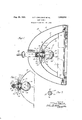
- FIG. 1 is vs ectionaljelevationthroughga headlamp embodying. the invention
- f Fig. ,2 is a sectional plan iew of. a portion lot-the headlight shown inFig. 1 and 'Fig., 3 ⁇ is a section' -off t e: ee e, taken a th l eseao r zvx a a
- Theinyfention has been'illustratedin conneuon wa se headlamp-1O of'a designinfcluding "an outer casing 11 and a reflector 12"1nounte'd within the;
- “samefl ⁇ contact tube 15 is mounted at "the center of the .re- V flector 1 and holds' the electrical contacts 'wliich 'com plete the circuit between the ⁇ outside electrical source, to which connection is:
- A-replacementunit has-alsobeen Shown as mountedy'in the headlamp andcomprise's' Another ob ect of the inventions map e-f and binding the "member 7 H u 1g 7 1 1: 7 ,1! M19 v It is apparent that rotation'of the'nut 170 ed'to bind against the-'"first men-tionedn'ut' 170 through 'a w asheru73 -s Ax'centra'l pmr f tion 7470f thewashei 73liesin a'plane'pen an outer portion?
- screwthreadedand is adapted-to receive a nuto 170 in ':screw-threadedengagement therewith 1 which is designed tobe "moved-into: closee ngagement with a Washer .71,- contactingiwith the-central outer'tjedge of the .ErefiectOr-QGO reflectors to 1 the holding: v r I inra directio'nto tighten the 's'ame upon the socket 66,; will tend tol force' holding member 65 inwardly against the inclined ends 70 of the socket arms, 69', thisfoper'ation; as will appear E from. the description succeeding,
- the plug 67 may be provided with out stsnding oppc tely pcsit o ed lugsBQ, l" may be tamped n t 1e sides, as shown'in Fig. 1, to enter the bayonet slots 131 formed in the ends of the movable contact tube 15, this structure being the usual headlamp construction.
- the socket 618 is adapted to re e ve the base of he hoop and hold the same in proper contacting relationship with the replacement reflector
- the plug 61 is adapted also to hold by means 0 a dielectric cylinder 81, a suitable contact rod 89 movable axially therethrough and adapted to conduct the electric current to the bulb.
- connection intermediate the lamp bulb .80 and the replacement lamp socket 66 is shown combined with means for preventing glare from the reflector which is the subject of the present invention.
- a stain ing is made which at its central part is in t shape of a sector till, this sector forming a shell conforming to the curvature of the lamp bulb 30 and covering a limited portion thereof, extending from a point somewhat below the axis of the reflector including the filament of the lamp, to a point in front of a plane passing transversely through the filamentot the lamp and above the axis thereof.
- the upper boundary of the sector is adapted :to he in a surface formed by passing a plurality of lines from the focal" point 91 of the reflector, at which the filament of the lamp is positinned, to the outer edge of the replacement or secondary reflector 60, or, as indicated in Fi 1, in a. plane transverse to the lamp axis and in front of the filament.
- the shield 90 is of such dimensions that rays of light emerging at the focus of the reflector 'will be. stopped by the shield 90 from passage to the front of the reflector above a. "plane including the. base 92 of the shield parallel to a lane passing to the axis of the reflector.
- the shield 90 is held in position on the lamp bulb hymeans of lateral bands 9 '95, which extend toward the base of the lamp and terminate in semi-cylindrical half tubes 96 and 97, the ends of the tube adjacent the strip or band 94, having a greater diameter than the outer end 98,
- the two cooperating tube elements 96 and 97 are adapted to fit over the base 100, of the lamp bulb and include between their edges the projecting pins'IOI formed-integral with the base of the lamp.
- the edges '99 of the tube members96 and 97 adjacent the pins "101 are somewhat inwardly curved to form surilamas adapted to contact with the pins 101 and thus retain the shield elements from axial movement'onthe lamp'base.
- the portion of the tubes 96 and 97 adjacent the lamp bulb have a curvature less than the outer ortions 98 so that when the nut 170 is r0 'ated in such a direction as to force the holding portion 65 u on the socket 66, the fingers 69 of the soc, et crowd the holding tubes 96 and 97 jamming the same into contact with the lamp base and thus uniting the whole into one solid unit from which the possibilityof vibration and rotation due to ar or movement of the support is entirely eliminated.
- the filaments generally used are of V- formation lying in a plane, the apex of the V being toward the front of the lamp. In order to give an undistorted reflection, the V plane is horizontal and the plane including the front edge 92 of the shield should also be horizontal in order to cut off the rays of light emerging from the V filament above a plane passing therethrough;
- Another aspect of the invention merit-ing attention is the combination of the shield of the straps 94L and95 with the by means shells 96 and 97, these shells being clamping of a thickness approaching that of the pins;
- This construction permits rotation of v r the base of the lamp so asto place the filament in horizontal position and also in proper relationship with the replacement re flector where the reflector employed is. of I the flat-lite type having'verticalbar sections. This adjustment may beeither in ro-" tation or in axialmovement; the construction permitting either adjustment, one as readily as the other.
- a glare screen comprising'a body having a screen formed as a segment of asphere and a supporting shank extended radially from the rear of said body and construc'ted to be interposed longitudinally between'the base of a lamp bulbvand its socket.
- a glare screen comprising a body hav- 7 ing a screen formed as a segment ofa sphere and a supporting shank extended radially from therear of said body and'constructed to beint'erposed longitudinally between the base of a'lamp means upon "said shank interlocking with I bulb and its/socket;
- a lamp inserted within a lamp said socket; a light shield of'approximately semi-spherical shape positioned in front of the lamp base,said shield having a cutaway portion; and means positioned between the adjacent wallsof said socket and lamp I base for supporting said shield;
Landscapes
- Engineering & Computer Science (AREA)
- General Engineering & Computer Science (AREA)
- Non-Portable Lighting Devices Or Systems Thereof (AREA)
- Vessels And Coating Films For Discharge Lamps (AREA)
Description
Aug. 25, 1931. s. F. ARBUCKLE ETAL LAMP SHIELD Original Filed Jan. 28,; 1924 5 INVENTOR ANUEL In HR uc/a BY FHRL gar/("51X ATTORNEY or .PAT'EBS NQNEW Patented Aug. 25, 19311;
r that? saint-n "Original application filed January 28 1924-, seri a1 uo;ess,'947.- Divided ,11927. SerialNo; 194,564.
I Thisinrention mates to, automobilehjead lights and particularly to a shield adapted to be used connection with, a light; bulb in a headlight for cutting; oficertain of the rays projected by saidfbulb." lhe application isa division of our copendi-ng applica tion entitled Headlamp replacement unit filed January 28, 1924 Serial 'No. 688,947, which eventuated :into- Patent Number "1,704,02 on March 5,,1929.-
-:One of the objects of' the inVention isjto providea shield fora headlamp bulb which may-besupported upon the base-of thebulb.
Another object ofthe inventionis to proli ide .a lamp shield which may beremovably supported, within the, headlamp; Q
Vision of a shield adapted to be positioned utilizedon amo ving vehicle, and iinosuch ni'r weather conditions where the presence" of fog or mist makes it exceedingly diflicult to operate avehicle, safely r i Other objects oithe invention andobjects involving the details oi construction and methods of manufacture :will becomeapparent on consideration of {the specificem ibodi-ment of theinvention which-may be refierred and which is herein described and illustrated in the accompanying drawing in whi'ch;.-, j
o :Fig; 1' is vs ectionaljelevationthroughga headlamp embodying. the invention; f Fig. ,2 is a sectional plan iew of. a portion lot-the headlight shown inFig. 1 and 'Fig., 3 {is a section' -off t e: ee e, taken a th l eseao r zvx a a Theinyfention has been'illustratedin conneuon wa se headlamp-1O of'a designinfcluding "an outer casing 11 and a reflector 12"1nounte'd within the; "samefl {contact tube 15 is mounted at "the center of the .re- V flector 1 and holds' the electrical contacts 'wliich 'com plete the circuit between the {outside electrical source, to which connection is:
made by the cordf29sandthe lamp bulb '30;
" A-replacementunit has-alsobeen Shown as mountedy'in the headlamp andcomprise's' Another ob ect of the inventions map e-f and binding the "member 7 H u 1g 7 1 1: 7 ,1! M19 v It is apparent that rotation'of the'nut 170 ed'to bind against the-'"first men-tionedn'ut' 170 through 'a w asheru73 -s Ax'centra'l pmr f tion 7470f thewashei 73liesin a'plane'pen an outer portion? 5 lies in a surface inclined to theaplane' oi the central portion '74; iTh'e outer: portion -7 5 I of the 5 washer 73 isvsplit a reflector b ot the outer edge of is adapted to bear against the mainzrefiector 12in order to aid ins'upporting the resm t: F; influentia meet ngs imnk, mem s; fiiiin chat: or? nnockwAr,
7 I messy, VASSIVGNORS TO; LjIONOGRAM ens; conronnmro mpr E TQMI EIG NL O PO T ON DEP A EI- i "natesin a radiallylextendingflange :61 which i I placement unit intheheadlamp. I-he center "offthe refiector'iis cutto form'a central 'aperture63, in whichziszadapted to be posiv tioned the shoulder 640i a'oholding member 65. iThe member 65 ;is;positioned upon a gtube' 66 forming. a ,plug;67 ofndiminished 3 cross section and aasocket 68 of increased cross section,=the ends of thesocket 68 extending within the reflector as separate.
=yieldingw'arms 69rhaving outturnedend's-YO. The holding member 65 restsi uponuthesef socket ends 69. adjacent to "the outturned portions 70. -;Tl1e socket-adjacentthe-junce 2 tion :ioffthe plugm67; is. externally; screwthreadedand is adapted-to receive a nuto 170 in ':screw-threadedengagement therewith 1 which is designed tobe "moved-into: closee ngagement with a Washer .71,- contactingiwith the-central outer'tjedge of the .ErefiectOr-QGO reflectors to 1 the holding: v r I inra directio'nto tighten the 's'ame upon the socket 66,; will tend tol force' holding member 65 inwardly against the inclined ends 70 of the socket arms, 69', thisfoper'ation; as will appear E from. the description succeeding,
binding" the reflector closely "to its :means 'ofsupport. m 1 Similarly positionedon the screw-threadp o "85 I ed socket is a second 'niiti72 which is adapt pendicular to 'theaxis of the socketfifiand radially to form a plurality:f ofi sectors 7 6 2, Projections ends of the sectors 76 contacting against the surface of the original or primary reflector 12 of the headlamp, yieldingly maintaining the .66 in proper relationship therewith. a Y
The plug 67 may be provided with out stsnding oppc tely pcsit o ed lugsBQ, l" may be tamped n t 1e sides, as shown'in Fig. 1, to enter the bayonet slots 131 formed in the ends of the movable contact tube 15, this structure being the usual headlamp construction. The socket 618 is adapted to re e ve the base of he hoop and hold the same in proper contacting relationship with the replacement reflector In addition to serving as a connecting was between the contact tube 15 and lamp 80, the plug 61 is adapted also to hold by means 0 a dielectric cylinder 81, a suitable contact rod 89 movable axially therethrough and adapted to conduct the electric current to the bulb. I 1
This form of connection intermediate the lamp bulb .80 and the replacement lamp socket 66 is shown combined with means for preventing glare from the reflector which is the subject of the present invention, From a strip ofmetal a stain ing is made which at its central part is in t shape of a sector till, this sector forming a shell conforming to the curvature of the lamp bulb 30 and covering a limited portion thereof, extending from a point somewhat below the axis of the reflector including the filament of the lamp, to a point in front of a plane passing transversely through the filamentot the lamp and above the axis thereof. The upper boundary of the sector is adapted :to he in a surface formed by passing a plurality of lines from the focal" point 91 of the reflector, at which the filament of the lamp is positinned, to the outer edge of the replacement or secondary reflector 60, or, as indicated in Fi 1, in a. plane transverse to the lamp axis and in front of the filament. In other i'fli'ds, the shield 90 is of such dimensions that rays of light emerging at the focus of the reflector 'will be. stopped by the shield 90 from passage to the front of the reflector above a. "plane including the. base 92 of the shield parallel to a lane passing to the axis of the reflector. onsequently, light rays will mnerge only as reflected from the surface of the reflector or such as pass out direetly beneath the base 99 of the shield secmi- :90, these lflyi being inclined downwardly from the horizontal axial plane and thus not causing any glare to, an observer in front of the lwadlump. 3
Depending from the mnercdge of the sec or in and xtendmg in a circular dlreo tien aroun t e lamp b ll es as t oin oppeslte sid s of he sector IS: a. hand .9 ,i 2l1 same erving both as an. uxili ry ho ding means for retaining the shield 90 in position and also as a shield for preventing the passage of direct rays of the lamp filament to that-portion 24 of the original or primary reflector 12 which extends beyond the outer edgeof the secondary reflector plane 61. The shield 90, is held in position on the lamp bulb hymeans of lateral bands 9 '95, which extend toward the base of the lamp and terminate in semi-cylindrical half tubes 96 and 97, the ends of the tube adjacent the strip or band 94, having a greater diameter than the outer end 98, The two cooperating tube elements 96 and 97 are adapted to fit over the base 100, of the lamp bulb and include between their edges the projecting pins'IOI formed-integral with the base of the lamp. The edges '99 of the tube members96 and 97 adjacent the pins "101 are somewhat inwardly curved to form surilamas adapted to contact with the pins 101 and thus retain the shield elements from axial movement'onthe lamp'base. The portion of the tubes 96 and 97 adjacent the lamp bulb have a curvature less than the outer ortions 98 so that when the nut 170 is r0 'ated in such a direction as to force the holding portion 65 u on the socket 66, the fingers 69 of the soc, et crowd the holding tubes 96 and 97 jamming the same into contact with the lamp base and thus uniting the whole into one solid unit from which the possibilityof vibration and rotation due to ar or movement of the support is entirely eliminated. "The filaments generally used are of V- formation lying in a plane, the apex of the V being toward the front of the lamp. In order to give an undistorted reflection, the V plane is horizontal and the plane including the front edge 92 of the shield should also be horizontal in order to cut off the rays of light emerging from the V filament above a plane passing therethrough;
Attention is drawn also to the utility of the shield in preventin glare under varied Weather conditions especially in foggy Weather Where the light rays emerging from the lamp are subjected to multiple reflection from the various vapor particles, causing-- such diffusion of illumination as, to make it exceedingly difilcult for the operator of the.
'carto visualize the objects in the path of m m nt f. the vehicle. It has been found that by eliminating the rays of light which emerge in an upward direction from the headlamp that this secondary reflection of the light beam is very largelyeliminated so that much clearer vision is obtained to the opcmtorthan would be obtainable, Without the employme t of the shield 90. The aperture bounded by the shield 90 and th band 93,. however, permits the emergence of those direct rays which illuminate. the
where illumination is essential.
Another aspect of the invention merit-ing attention is the combination of the shield of the straps 94L and95 with the by means shells 96 and 97, these shells being clamping of a thickness approaching that of the pins;
101. This construction permits rotation of v r the base of the lamp so asto place the filament in horizontal position and also in proper relationship with the replacement re flector where the reflector employed is. of I the flat-lite type having'verticalbar sections. This adjustment may beeither in ro-" tation or in axialmovement; the construction permitting either adjustment, one as readily as the other.
While We have shownthe shield in-connection with a replacementvreflec'tor it is to I, i
be understood that it may also be used ad-- vantageously in one of the'ordinaryltype'.
Various other modifications of the 1nven-' tion will become apparent to those skilled in the art and therefore it is desired to pro tect fully all such modifications as come within the spirit of the invention and as defined by the claims hereto appended.
Having thus described the invention, what is claimed is: n- 7 a 1. A glare screen comprising'a body having a screen formed as a segment of asphere and a supporting shank extended radially from the rear of said body and construc'ted to be interposed longitudinally between'the base of a lamp bulbvand its socket.
2. A glare screen comprising a body hav- 7 ing a screen formed as a segment ofa sphere and a supporting shank extended radially from therear of said body and'constructed to beint'erposed longitudinally between the base of a'lamp means upon "said shank interlocking with I bulb and its/socket; and
cooperatinglneans upon the lamp base to prevent relative movements of the parts."
3. In an electric lamp shield construction, i
socket; a lamp; base inserted withina lamp said socket; a light shield of'approximately semi-spherical shape positioned in front of the lamp base,said shield having a cutaway portion; and means positioned between the adjacent wallsof said socket and lamp I base for supporting said shield;
In testimony whereof, we affix our signatures. c SAMUEL F. ARBU'CKLE.
CARL P; BROCKWAY.
Priority Applications (1)
| Application Number | Priority Date | Filing Date | Title |
|---|---|---|---|
| US194564A US1820522A (en) | 1924-01-28 | 1927-05-27 | Lamp shield |
Applications Claiming Priority (2)
| Application Number | Priority Date | Filing Date | Title |
|---|---|---|---|
| US688947A US1704028A (en) | 1924-01-28 | 1924-01-28 | Head-lamp replacement unit |
| US194564A US1820522A (en) | 1924-01-28 | 1927-05-27 | Lamp shield |
Publications (1)
| Publication Number | Publication Date |
|---|---|
| US1820522A true US1820522A (en) | 1931-08-25 |
Family
ID=26890161
Family Applications (1)
| Application Number | Title | Priority Date | Filing Date |
|---|---|---|---|
| US194564A Expired - Lifetime US1820522A (en) | 1924-01-28 | 1927-05-27 | Lamp shield |
Country Status (1)
| Country | Link |
|---|---|
| US (1) | US1820522A (en) |
-
1927
- 1927-05-27 US US194564A patent/US1820522A/en not_active Expired - Lifetime
Similar Documents
| Publication | Publication Date | Title |
|---|---|---|
| US1676464A (en) | Headlight | |
| US1820522A (en) | Lamp shield | |
| ES279983U (en) | Non dazzling vehicle headlamp. | |
| US3317772A (en) | Headlight arrangement for automotive vehicles including a reflector and a light shield means | |
| US1992041A (en) | Light projector | |
| US1712027A (en) | Light-projecting device | |
| US1689378A (en) | Automobile head lamp | |
| US1704028A (en) | Head-lamp replacement unit | |
| US1274217A (en) | Glare-subduing and light conserving and distributing device for head-lights of automobiles, &c. | |
| US1548294A (en) | Headlight | |
| US2262098A (en) | Head lamp of motor vehicles | |
| US1399378A (en) | cltjley | |
| US2071979A (en) | Electric incandescent lamp | |
| US2045512A (en) | Electric incandescent lamp | |
| US1720311A (en) | Vehicle light | |
| US1431964A (en) | Headlight for road vehicles or the like | |
| US1987112A (en) | Means for deflecting headlight rays | |
| US2129814A (en) | Lamp attachment means | |
| US2027690A (en) | Vehicle headlight | |
| US2148965A (en) | Composite light | |
| US1520192A (en) | Dimmer for headlights | |
| US1843577A (en) | Incandescent bulb | |
| US1960049A (en) | Attachment for electric lamps | |
| US1513715A (en) | Headlamp for automobiles | |
| US1313716A (en) | Salvatobe mazzeo |