US1820249A - Machine for making coat hangers - Google Patents
Machine for making coat hangers Download PDFInfo
- Publication number
- US1820249A US1820249A US339380A US33938029A US1820249A US 1820249 A US1820249 A US 1820249A US 339380 A US339380 A US 339380A US 33938029 A US33938029 A US 33938029A US 1820249 A US1820249 A US 1820249A
- Authority
- US
- United States
- Prior art keywords
- stock
- machine
- shaft
- carrier
- cutting
- Prior art date
- Legal status (The legal status is an assumption and is not a legal conclusion. Google has not performed a legal analysis and makes no representation as to the accuracy of the status listed.)
- Expired - Lifetime
Links
- 238000005520 cutting process Methods 0.000 description 20
- 241000283707 Capra Species 0.000 description 1
- RUPBZQFQVRMKDG-UHFFFAOYSA-M Didecyldimethylammonium chloride Chemical compound [Cl-].CCCCCCCCCC[N+](C)(C)CCCCCCCCCC RUPBZQFQVRMKDG-UHFFFAOYSA-M 0.000 description 1
- 239000000428 dust Substances 0.000 description 1
- 239000000463 material Substances 0.000 description 1
- 238000009966 trimming Methods 0.000 description 1
Images
Classifications
-
- B—PERFORMING OPERATIONS; TRANSPORTING
- B27—WORKING OR PRESERVING WOOD OR SIMILAR MATERIAL; NAILING OR STAPLING MACHINES IN GENERAL
- B27M—WORKING OF WOOD NOT PROVIDED FOR IN SUBCLASSES B27B - B27L; MANUFACTURE OF SPECIFIC WOODEN ARTICLES
- B27M3/00—Manufacture or reconditioning of specific semi-finished or finished articles
- B27M3/24—Manufacture or reconditioning of specific semi-finished or finished articles of household utensils, e.g. spoons, clothes hangers, clothes pegs
Definitions
- Fig. 1 is a side e16 vation of my lnyention, part of theyiew be- ;ing in section, taken on theline 1 .1 of Fig. 3; Fig.2 is a plant; F ig, 3fis a section taken I W of Pa of para e angle wo kig fifi,
- Fig.,4 is a perspective View of two lof the mat hanger stock blanksniade by my improvedmachine Fig.
- Fig. G is an enlargejd sectiontaken' onthe line 6 6, of Fig. e 5;
- Fig. 7 is a section taken on the line'7'.,7' of I it: ;:Fig. 3, an-d'Fig. .8, is a sideelevation of;
- suitable f ran1e comprising a clustear. of fiveanglelposts 110,. provided with kstaa bilit-y foot Iopieces; 11, and corner braces :12; said foot pieces, beingv mounted. upon ga suit 7 p r ;a-;-track along whichjthe coat hangerastock j) j i able base 13.
- P The top"portionbfithejifr'ame is braced lbyfthearadiating angle members: 14, I which are secured. to the circular 'flange of a journal. bearing '16 'to';;producei a; rig d frame is a hollow shaftfA; which isjournaled in they journal bearing 16.
- This shaft is wdriyen'by the bevel;-gear -19 -or any other suit- I .able drive; and-carries a horizontalturn' table 1 20 which is rigidly clamped to said shaft by bolt 21; gor other suitable means.
- the primary @fu'nction ot the. turn table is. to carry two moto -dri e lc in-gzelemen s; BV and? :C, I
- Theband36 is fastened tosaidposts to-@1 5 I g augmen erig d yjqf them i -i meand 1 Y r-sa i'd guides project inwar'dlywiththeir inner I extremities fii shwith the-inner surface of the ib 'n i 3 to pr vide.
- piecesv of, stock may be fed into thev machine r constitute coat'hanger, stock holders and--as' shownproyide means by; which a pl-ur'ality of- 5 simultaneously. to .beoperated upon; by the painof motor driven cutting; elementsv :B.
- Therwork.oristdcknsually is composed oi w ood or other suitable mate, j grial and is fed inwardly byahooki 42 over its y outer lend attached to a flexible, .cord :43 run- .ning overa pulley 4 and attached toawei-ght 00 45,? said pulley being journa led zby brackets 1 of bell crank 50 up relieves tension of presser "spring pressure.
- the stock piece is clamped near its inner end upon the pair of work guides by means of the transverse presser foot 47 while the motor driven cutting elements B and C are performing their cutting function, there being a presser foot and its co-operating parts provided for each pair of guides.
- the presser foot is held by an upwardly extending thrust rod 48 threaded thereinto and held adjusted by lock nut 49.
- the upper end of thrust rod 48 passes freely through the lower arm of a bell crank 50 and isheld under adjustable tension of spring 51 so that tilting foot 47 to permit the stock sliding in against stop 41 and downward movement applies the pressure foot to hold the stock rigidly under
- the ends of the presser foot 47 are slotted at 52 (see Fig.
- the bell crank 50 is journaled at its angle upon the supporting shaft 17 "mountedupon radiating braces 14 and said bellcrank'isrevolubly held between collars 53 on said shaft.
- the upper arm of the bell crank is operated by a thrust rod 54 which carries on its inner end an antifriction roll 55. Said roll is movably held agalnst the surface of a cam 56 by means of a stirrup 57 a which is pivoted upon the flange 15 of the stationary bearing 16.
- the cam is soshaped as'tocause each presser foot 47'to hold the stock D stationary while the cutting elements "are performing their work and to immediately release the stock and allow the feeding device42 to functionafter the cutting elementspass on to a succeeding stock feeding element as the shaft A revolves.
- the cutting elements perforrntheir function successively upon the succession of stock ter element B so as to cut the sides of a pair pieces held by'the several holding and feedingdevices.
- the presser foot is raised to release the stock after-each cutting operation by means of springs 71 on the sides of the guides 35, the combined tension of said ters, threein number as'shown and of equal diameter, are assembled at evenly spaced intervals apart on-the vertical shaft'27 of cutof coat hanger blanks 59 and 60 evenly as the turntable revolves.
- the'cutters 28 perform their function the inner concave cutters 28' lyingbetween and of less diameter than cutters 28, round the inner edges of the Utongues or coat hanger blanks 59 and 60 as a by the cup saw. 1
- the work or stock piece D can be built up in rough out of pieces of material glued together so as to utilize the last curved cut made
- the hollow shaft A is provided with a duct 62 near the turn table which has an orifice near the cutting elements and said shaft is connected with a suction duct 63 at its upper end which is adapted to remove saw dust as the cutters function.
- Suitable commutator rings 64 on the shaft A also provide electrical connections for the motors 25 and 30.
- a machine for making coat hanger blanks comprising, in combination, a carrier revoluble about a vertical axis, means for revolving said carrier, a motor driven cutting element mounted upon-said carrier and adapted to move in a circular path concentric with said axis, a'stop on said carrier against which the stock is adapted to be adjusted with its inner end across the cutting path of said cutting element, a plurality of stock holders distributed around said axis and adapted to present a series of pieces of stock against said stop and to the successive cutting action of said cutting element as the latter revolves about said axis, each of said stockholders comprising a guide support for holding and guiding a piece of stock across the path of said cuttingelement and against said stop, clamping means co-acting with said holder for securing the stock while thec'utting element is performing its function. and for releasing the stock thereafter, and cam operated means connected with said shaft for applying and releasing said clamp automatically.
- a machine for making coat hanger blanks comprising, in combination, a carrier 1 revoluble about a substantiallyvertical axis, a means for revolving said carrier, a Stock: holder cooperating with said carrier and v 5 adapted to present stock in a plane intersectr ing said axis at an angle, a motordriven gang of cutterson said carrier adapted to'be moved in a circumferential path to describe a plurality of substantially horizontal and;
- a machine'fonmaking coat hanger blanks and theylike comprising, in combina f tion, a'carrierrevoluble about'a vertical axis,
- each of said stock holders comprising a'guide support for lioldingand guiding a piece of stock across I the path of said cutting element and against c said stop, clamping meansco-acting with said holder for securing the stock While the cutting element is performing its function for releasing the stock-thereafter, and
Landscapes
- Engineering & Computer Science (AREA)
- Life Sciences & Earth Sciences (AREA)
- Manufacturing & Machinery (AREA)
- Wood Science & Technology (AREA)
- Forests & Forestry (AREA)
- Treatment Of Fiber Materials (AREA)
Description
Aug. 25, 1931. w. .1. REHRIG MACHINE FOR MAKING GOAT HANGERS Filed Feb. 12. 1929 3 Sheets-Sheet. l
I INVENTOR; BY; 176% M Y M A TTORNE VS.
Aug. 25, 1931. w. J. REHRIG 1,820,249
MACHINE FOR MAKING COAT HANGERS Filed Feb. 12, 1929 3 SheetsSheet. 2
INVENTOR,
562mg I Aug. 25, 1931. w. J. REHREG 1,820,249
MACHINE FOR MAKING COAT HANGERS v Filed Feb. 12, 1929 3 Sheets-Sheet. 3 I
11v VENTOR, By wzzz'm jfi zr z ATTORNEYO.
Patented A g. 25 1931 MACHINE non MAKING- vcoA'r HANGERS Y? I Application and February 12 My. invention relates to improvements .in
' 127 on.a. vertical a'xisand (carrying-at its. 111)- per Jend a plurality, of circulargcutters -28, suitably spaced. apart with intervening, c0
" cave cutters 28'. ;,Cut ting element 6 consists: 7 ofa motcrf80 monntediby upwardlyextend jing bracket 31on the turn table with its'drive v I shaft 132 disposed-on an axis radiating from 1 machines-for making coat hangers5'the' pri mary object being to providepmeans for making aj maXimumnumber of what lfhave flfchosen to term coat hanger blanks :With a: minimum of expense and labor. With these and other objects in View myinvention comprises the features of con'structionand combination of partshereinafter described and claimed; I
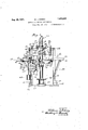
In the accompanying drawingsforming- 2 'partof this specification, Fig. 1 is a side e16 vation of my lnyention, part of theyiew be- ;ing in section, taken on theline 1 .1 of Fig. 3; Fig.2 is a plant; F ig, 3fis a section taken I W of Pa of para e angle wo kig fifi,
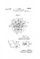
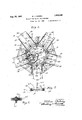
' on the'lin'e 3-3 of.F ig.'r1-;Fig.,4 is a perspective View of two lof the mat hanger stock blanksniade by my improvedmachine Fig.
' 5 isa-perspective View ,ofa leoathanger blank j formed: their function; and prior torthe ,final I cutmadeby the cuppedsa'w'; Fig. G is an enlargejd sectiontaken' onthe line 6 6, of Fig. e 5; Fig. 7 is a section taken on the line'7'.,7' of I it: ;:Fig. 3, an-d'Fig. .8, is a sideelevation of; one
- of the cuttin-gele'mentsh';a
after the. trimming saw bladeshave ;per-
-My improvedmaehlne:
suitable f ran1e,-that shown comprising a clustear. of fiveanglelposts 110,. provided with kstaa bilit-y foot Iopieces; 11, and corner braces :12; said foot pieces, beingv mounted. upon ga suit 7 p r ;a-;-track along whichjthe coat hangerastock j) j i able base 13. P The top"portionbfithejifr'ame is braced lbyfthearadiating angle members: 14, I which are secured. to the circular 'flange of a journal. bearing '16 'to';;producei a; rig d frame is a hollow shaftfA; which isjournaled in they journal bearing 16. This shaft is wdriyen'by the bevel;-gear -19 -or any other suit- I .able drive; and-carries a horizontalturn' table 1 20 which is rigidly clamped to said shaft by bolt 21; gor other suitable means. The primary @fu'nction ot the. turn table is. to carry two moto -dri e lc in-gzelemen s; BV and? :C, I
structure. Arranged ,-,c vertically; in this at its. lower end in ,aj step 'bearingll8 on the base 13. 7 The yupperendbf said. shaft; turns which: are. revolved -in.ahorizontal plane to gpertorm their work.
Cutting element B,consists' ef atmotor 25 mounted. depending bracket :26 upon the is assembled I in a *andCm 'f :1 =1 HIP, gSecurjed to the outer ;edge.o.f..the turn table by. brackets 40 and concentric.therewithfis a circular stop. or ,band l1',1 which is so-pojs'il 5 *tioned asv t0 provide-a moving stop against fwrpmmfafnnfinreior?testenemas;ciiniiioamn 'fj ,1929. seriai mi. 339, 80. 7
militant 3.1.01 mung-ta Ministerial shalt r th ve ticalv ax s o h m n d veshaft; A
and inclined upwardly and outwardly from no I five in number/being shown but anyisnitable.
nd -are s ppo d by cro s members-1,38, h. 1 711 r carried by downwardly and inwardlyinclinedbracesl 39-. ;The 1owerf .ends of gthese 'bracesare secured ;;to the posts 10 Theband36 is fastened tosaidposts to-@1 5 I g augmen erig d yjqf them i -i meand 1 Y r-sa i'd guides project inwar'dlywiththeir inner I extremities fii shwith the-inner surface of the ib 'n i 3 to pr vide. l arance for-the cup gi l-ides of each '{pairfface inwardly to provide :may'be fed into the maehineiaiz-The guidesf 35.
: piecesv of, stock may be fed into thev machine r constitute coat'hanger, stock holders and--as' shownproyide means by; which a pl-ur'ality of- 5 simultaneously. to .beoperated upon; by the painof motor driven cutting; elementsv :B.
which the" inner. endslofthewo1 k or stock 5 pieces]? are fed. Therwork.oristdcknsually is composed oi w ood or other suitable mate, j grial and is fed inwardly byahooki 42 over its y outer lend attached to a flexible, .cord :43 run- .ning overa pulley 4 and attached toawei-ght 00 45,? said pulley being journa led zby brackets 1 of bell crank 50 up relieves tension of presser "spring pressure.
46 between each pair of stock guides and secured to the supporting band 36.
The stock piece is clamped near its inner end upon the pair of work guides by means of the transverse presser foot 47 while the motor driven cutting elements B and C are performing their cutting function, there being a presser foot and its co-operating parts provided for each pair of guides. The presser foot is held by an upwardly extending thrust rod 48 threaded thereinto and held adjusted by lock nut 49. The upper end of thrust rod 48 passes freely through the lower arm of a bell crank 50 and isheld under adjustable tension of spring 51 so that tilting foot 47 to permit the stock sliding in against stop 41 and downward movement applies the pressure foot to hold the stock rigidly under The ends of the presser foot 47 are slotted at 52 (see Fig. 7 to re ceive vertical sides of guides 35and assist H1 guiding the presser foot in its action without turning. The bell crank 50 is journaled at its angle upon the supporting shaft 17 "mountedupon radiating braces 14 and said bellcrank'isrevolubly held between collars 53 on said shaft. The upper arm of the bell crank is operated by a thrust rod 54 which carries on its inner end an antifriction roll 55. Said roll is movably held agalnst the surface of a cam 56 by means of a stirrup 57 a which is pivoted upon the flange 15 of the stationary bearing 16. The cam is soshaped as'tocause each presser foot 47'to hold the stock D stationary while the cutting elements "are performing their work and to immediately release the stock and allow the feeding device42 to functionafter the cutting elementspass on to a succeeding stock feeding element as the shaft A revolves. In this manner the cutting elements perforrntheir function successively upon the succession of stock ter element B so as to cut the sides of a pair pieces held by'the several holding and feedingdevices. The presser foot is raised to release the stock after-each cutting operation by means of springs 71 on the sides of the guides 35, the combined tension of said ters, threein number as'shown and of equal diameter, are assembled at evenly spaced intervals apart on-the vertical shaft'27 of cutof coat hanger blanks 59 and 60 evenly as the turntable revolves. As the'cutters 28 perform their function the inner concave cutters 28' lyingbetween and of less diameter than cutters 28, round the inner edges of the Utongues or coat hanger blanks 59 and 60 as a by the cup saw. 1
shown in Fig. 6, to produce a smooth rounded lower or inner edge on each blank. Immediately following the action of these cutters 28, the cup saw 33, which is mounted upon the upper and outer end of shaft 32 of the cutter element C cuts the pair of coat hanger blanks 5.9;and 60 from the stock piece along the lines of the kerfs left by the horizontal cutters 28, thus producing a pair of completed curved coat hanger blanks 61, of even width and thickness such as shown in Fig. 4. These blanks as cut by the cup saw drop and can be removed from the machine by any suitable conveyer means not shown. The work or stock piece D can be built up in rough out of pieces of material glued together so as to utilize the last curved cut made The hollow shaft A is provided with a duct 62 near the turn table which has an orifice near the cutting elements and said shaft is connected with a suction duct 63 at its upper end which is adapted to remove saw dust as the cutters function. Suitable commutator rings 64 on the shaft A also provide electrical connections for the motors 25 and 30.
As the machine operates an attendant following the action of the cutters may from time to time replenish the used stock in each pair of guides 35. Otherwise the operation of the machine is automatic. The machine operates at high speed and produces a finished product of best quality. By cuttinga plurality of blanks at each operation of the cutters the output of the machine is increased. Having described my invention what I claim as new and desire tosecure by Letters Patent is:
1. A machine for making coat hanger blanks, comprising, in combination, a carrier revoluble about a vertical axis, means for revolving said carrier, a motor driven cutting element mounted upon-said carrier and adapted to move in a circular path concentric with said axis, a'stop on said carrier against which the stock is adapted to be adjusted with its inner end across the cutting path of said cutting element, a plurality of stock holders distributed around said axis and adapted to present a series of pieces of stock against said stop and to the successive cutting action of said cutting element as the latter revolves about said axis, each of said stockholders comprising a guide support for holding and guiding a piece of stock across the path of said cuttingelement and against said stop, clamping means co-acting with said holder for securing the stock while thec'utting element is performing its function. and for releasing the stock thereafter, and cam operated means connected with said shaft for applying and releasing said clamp automatically.
2. A machine for making coat hanger blanks, comprising, in combination, a carrier 1 revoluble about a substantiallyvertical axis, a means for revolving said carrier, a Stock: holder cooperating with said carrier and v 5 adapted to present stock in a plane intersectr ing said axis at an angle, a motordriven gang of cutterson said carrier adapted to'be moved in a circumferential path to describe a plurality of substantially horizontal and;
longitudinally circular cuts in the end of said stock on said holder correspondingwith the sides of coat hanger blanks, and a'motor driven cup saw on said carrier adapted to be moved in a circular pathto describe a curved cutoff severing theportions of stock pre-' pared bysaid gangof cutters into completed coat hanger blanks.
3. A machine'fonmaking coat hanger blanks and theylike, comprising, in combina f tion, a'carrierrevoluble about'a vertical axis,
means for revolving said carrier, a motor driven cutting element mounted upon said carrier and adapted'to move in a circular I path concentric withsaidaxis, astop on said vg5 carrieragainst which the stock is adapted to be adjusted ithits inner endacross'the cut-. ting path of said cuttingelemenna plurality I of stock holders distributed around said axis and adapted to presenta series of pieces of stock against. said stop and to the successive" cutting action of said cutting element as the latter revolves about said axis, each of said stock holders comprising a'guide support for lioldingand guiding a piece of stock across I the path of said cutting element and against c said stop, clamping meansco-acting with said holder for securing the stock While the cutting element is performing its function for releasing the stock-thereafter, and
' means actuated in synchronism with the I revolutionof said carrier. for applying and I releasing said clamp.
In Witness WhereofI have signed my name 7 to this specification.
a; I r WILLIAMJQR RIG.
con
Priority Applications (1)
| Application Number | Priority Date | Filing Date | Title |
|---|---|---|---|
| US339380A US1820249A (en) | 1929-02-12 | 1929-02-12 | Machine for making coat hangers |
Applications Claiming Priority (1)
| Application Number | Priority Date | Filing Date | Title |
|---|---|---|---|
| US339380A US1820249A (en) | 1929-02-12 | 1929-02-12 | Machine for making coat hangers |
Publications (1)
| Publication Number | Publication Date |
|---|---|
| US1820249A true US1820249A (en) | 1931-08-25 |
Family
ID=23328742
Family Applications (1)
| Application Number | Title | Priority Date | Filing Date |
|---|---|---|---|
| US339380A Expired - Lifetime US1820249A (en) | 1929-02-12 | 1929-02-12 | Machine for making coat hangers |
Country Status (1)
| Country | Link |
|---|---|
| US (1) | US1820249A (en) |
-
1929
- 1929-02-12 US US339380A patent/US1820249A/en not_active Expired - Lifetime
Similar Documents
| Publication | Publication Date | Title |
|---|---|---|
| US411925A (en) | Cut-off sawing-machine | |
| US1820249A (en) | Machine for making coat hangers | |
| US490877A (en) | lovell | |
| US1329755A (en) | Machine for halving or splitting peaches | |
| US1604347A (en) | Artichoke trimmer | |
| US2010865A (en) | Fruit splitter | |
| US1995026A (en) | Machine for trimming wall paper | |
| US1542554A (en) | Fruit-slice-cutting machine | |
| US1731715A (en) | dunlap | |
| US1807251A (en) | Process of producing veneers | |
| US691432A (en) | Machine for cutting cork disks. | |
| US907435A (en) | Carving-machine. | |
| US329846A (en) | myers | |
| US889276A (en) | Machine for cutting vegetables. | |
| US1263842A (en) | Fur-cutting machine. | |
| US144916A (en) | Improvement in flower-makers girass-cuttlng machines | |
| US334997A (en) | Gang-edger | |
| US1012995A (en) | Veneer-lathe. | |
| US274220A (en) | Franklin b | |
| US692356A (en) | Carving-machine. | |
| JPH06269269A (en) | Device for picking leaf | |
| US417709A (en) | Machine for sawing front strips for desks | |
| US131648A (en) | Improvement in machines for making boxes for elevators | |
| US266259A (en) | Machine for cutting the shafts or stems of feathers | |
| US473301A (en) | Brick and tile cutting machine |