US181775A - Improvement in cider and wine presses - Google Patents
Improvement in cider and wine presses Download PDFInfo
- Publication number
- US181775A US181775A US181775DA US181775A US 181775 A US181775 A US 181775A US 181775D A US181775D A US 181775DA US 181775 A US181775 A US 181775A
- Authority
- US
- United States
- Prior art keywords
- curb
- follower
- cock
- piston
- apron
- Prior art date
- Legal status (The legal status is an assumption and is not a legal conclusion. Google has not performed a legal analysis and makes no representation as to the accuracy of the status listed.)
- Expired - Lifetime
Links
- 235000019987 cider Nutrition 0.000 title description 7
- XLYOFNOQVPJJNP-UHFFFAOYSA-N water Substances O XLYOFNOQVPJJNP-UHFFFAOYSA-N 0.000 description 11
- 235000011389 fruit/vegetable juice Nutrition 0.000 description 5
- 230000002706 hydrostatic effect Effects 0.000 description 5
- 230000000284 resting effect Effects 0.000 description 4
- 238000010276 construction Methods 0.000 description 3
- 238000007599 discharging Methods 0.000 description 2
- 239000007788 liquid Substances 0.000 description 2
- 244000141359 Malus pumila Species 0.000 description 1
- 235000021016 apples Nutrition 0.000 description 1
- 230000000630 rising effect Effects 0.000 description 1
- 230000002459 sustained effect Effects 0.000 description 1
Images


Classifications
-
- B—PERFORMING OPERATIONS; TRANSPORTING
- B30—PRESSES
- B30B—PRESSES IN GENERAL
- B30B9/00—Presses specially adapted for particular purposes
- B30B9/02—Presses specially adapted for particular purposes for squeezing-out liquid from liquid-containing material, e.g. juice from fruits, oil from oil-containing material
- B30B9/24—Presses specially adapted for particular purposes for squeezing-out liquid from liquid-containing material, e.g. juice from fruits, oil from oil-containing material using an endless pressing band
Definitions
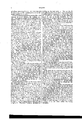
- FIG. 1 is a side elevation.
- Fig. 2 is a plan.
- Fig. 3 is an enlarged sectional view of the press-cylinder, curb, and follower.
- Fig. 4 is a cross-section of the four-way cock.
- Figs. 5, 6, and 7 are perspective, sectional, and elevation views, respectively, of the devices for shifting the cock.
- Fig. 8 is a plan of the bed and chute.
- the prime feature of this invention consists of a curb and follower resting over an endless apron, and acted upon by a hydrostatic press, to force the curb and follower down tok cut o' a section of the pomace on the apron and express the juice therefrom; thento raise them again, while the apron makes a forward movement to bring a new section beneath the curb, the action being thus intermittent.
- It also further consists of a four-way cock of peculiar construction, a shifting device for changing the cock, and a bed beneath the endless apron for carrying oi the juice, all constructed substantially as hereinafter described.
- A is a frame of any convenient construction.
- B B are two rollers at the ends of the frame, and C is an endless apron of canvas passing around the rollers.
- D is a vhydrostatic press resting over the front end of the machine, and sustained by strong rods bolted to the frame, or by any other means. 1t is fed by pipes c a', opening into the top and botrlhe piston b is attached to a rod, c, which extends above aud below the cylinder.
- E is the curb, and F is the follower, which parts are connected with the rod c by a balland-socket joint, (shown by dotted lines, Fig. 3,) which at top and bottom, and having vertical walls on the inside for the play of the follower.
- rIlhe follower is of the same shape in outline, n'lling the area of the curb, and connectedtherewith by longitudinal springs d d, passing through holes in the ends of the curb, or by any other kind of springs that will hold the follower to the top of the curb when not under pressure. rlhe edges of the follower which rest in the curb may be packed to prevent passage of the cider upward.
- G is an arm attached to the upper end of the rod c, and made adjustable vertically thereon by means of a set-screw, e.
- a connecting-rod H.
- V The bottom of the con necting-rod is similarly jointed to a block,f, which adjusts upon a pivoted arm, g, and is secured by a set-screw.
- This arm carries a pawl, h, which engages with a disk, c', operating a wheel, j, which engages with a pinion on the shaft of the pulley B, carrying the endless apron.
- the operation of this part of our invention is as follows: The curb and follower are forced down by reason of the water being let in 'through the upper pipe a, and pressing downward upon the piston b.
- the curb strikes upon the apron and incloses a section of the pomace thereon, and when seated, the follower is then pressed down by the excess of pressure so as to express the juice.
- a certain degree of pressure is attained, sufficient to express the juice, the ingress of water to the press is changed from the upper pipe a. to the lower one a', as will presently be described, and the follower and curb are thereby raised from the apron.
- the arm G gives motion to the connecting-rod H, arm g, and pawl h, thereby operating the rim t', wheel j, and roller B, and feeding the apron along in position. to receive another action of the curb and follower.
- the appara tus acts intermittently, alternately pressing a section of the pomace upon the apron, and then moving the apron up for a new action, doing the whole work automatically, and discharging the dry pomace over the end of the apron.
- the pomace may dropfrom the grinding apparatus directly upon the rear end of the apron, and the pressing be done as fast as the apples are ground.
- the lower edge ofthe curb is preferably made thin, so as to cut through the poinace readily.
- the ball-and-socket joint connecting the follower with the piston-rod is essential to allow the curb to adapt itself to position, and the follower to work without binding.
- the springs d d give the propel' elasticity to the follower, as Well as hold the follower up from the bottom of the curb, and they also serve as the connection between the Afollower and the curb, by which both parts are raised together in the upstroke of the piston.
- I is the force-pump, by which water is forced tothe hydrostatic press. Its piston-rod lc is operated by a crank-wheel, l, driven by a pulley, fm., on its shaft, or by any other means.
- n. is-the induction-pipe
- o is the eductionpipe, connected with said force pump.
- the eduction-pipe 0 extends to the four-way cock, and it also has a branch, o', which opens into the base of a regulating-cylinder, L.
- This cylinder has a piston resting therein, whose rod p extends upward, and has a weight, q, on top.
- the regulating-cylinder also has a discharge-pipe, r, which allows escape of the dead water therefrom.
- K is the four-way cock. It rests in a case, s, into which opens the four pipes a a o t.
- the pipeo is the feeding-pipe from the force-pump to the cock, and the pipes a a are the feeding-pipes from the cock to the hydrostatic press, as before described.
- the pipe t is simply a discharge or exhaust pipe for allowing escape of the deadwater from tbe press.
- the cock is provided with curved ports u u, Fig. 4, so arranged that in making a quarterturn of the cock the water is alternately turned on and off through the pipes a a by the shifting of the ports from one pipe to the other.
- M is adisk attached fast to the inner end of the cock, and having two pins or studs, e o',
- Fig. 7 projectingfrom its face.
- a loop, w which rests over the pin o.
- an arm, w that rests under the pin t.
- the sleeve N has an offset, y, on which rests a lever, P, connected at the front end to a hinged link, z, which forms the fulcrum, and having on its long end a counter-weight, c2, adjustable to any position by means of notches on the beam.
- the offset y which forms a bearing, rests a short shaft or pin', d2, having an arm, d3, upon which is hung a light weight, d4.
- the arm d3 rests in an open slot having an inclined side, y.
- lIhe rod p in line with the shaft d2, has a square shoulder, p2, with which the end of the shaft d2 engages when so forced inward.
- the end of the arm d3 is con-v nected with the outer edge of disk M, above the pin lv', by means of a chain or other ilexible connection, r', as shown.
- the arrangement above described forms the shifting device to the cock.
- the operation is as follows: The water is forced by pump I, through pipe o, into and through the cock,and thence through pipe aiuto the top of the hydrostatic press.
- sufcient to express the cider under the follower the overpressure t through the branch o. and beneath the piston in the regulating-cylinder L, raises the rod vp. and weight q.
- the loop w strikes the pin fv, and turns the disk M, thereby shifting the cock.
- the piston-rodp then falls.
- This shifting motion slaekens the chain r', andl allows the shaft d2 to press inward.
- the shaft d2 engages with Athe shoulder p2, and thesleeve N rises with ⁇ the pistod-rod.
- pipe o' is then raised through pipe o with the water from the pump.
- the chain r may have a soft link
- R is a bed, which rests beneath the curb E, and R is a chute beneath the endless apron.
- the bed R is a raised platform, and has a re:- movable rack, composed of slats s2 s2, Fig. 8, which is surrounded by a groove, t2, ending at the inner extremity in a spout, t3.
- chute R has corresponding grooves u2 u, ending in a common discharge, a3. At this point a side spout may run out to discharge the cider into a suitable vessel.
- the bed R serves to receive the pressure ofj the curb and follower, and the liquid which, passes through the apron runs between the.
- the weight 02 serves simply to force The
- the bed R is essential to receive and support the apron ⁇ This press is adapted to ⁇ pressing Wine and. other liquids, as well as cider.
- the bed R consisting of a raised platform, resting under the curb and supporting the endless apron, and constructed With the slats .s2 s2 and grooves t2 t2, for allowing ready escape of the expressed juice, as described.
Landscapes
- Engineering & Computer Science (AREA)
- Mechanical Engineering (AREA)
- Fluid-Pressure Circuits (AREA)
Description
z sheets-sheet 1'. 0.12,. COWLEY & DpS. FARQUHARSON. CIDE?. AND WINE PRESS.'
No.181,775. Pazenzea sepas, 1am
Wa'zgnsses. /fzvwezzarg 2 Sheets-Sheet 2.
c. n. coWLEY & n. s?. FARQUHARsoN. CIDER'AND WINE PRESS. 110.181,775. Patented sept.5v,1a7s.
Jag-71 es; 6J. Zan?.
\ tom above and below the piston b.
UNITED STATEs 'PATENT OFFICE.
GOVEL R. OOWLEY AND DUNCAN S. FARQUHARSON, OF ROCHESTER, N. Y.
IMPROVEMENT IN CIDER AND WINE PRESSES.
Specification forming part of Letters Patent No. 181,775, dated September 5, 1876; application filed March 26, 1875.
To all whom it may concern:
Be it known that we, GOVEL R. GOWLEY and DUNCAN S. FARQUHARSON, both of the city of Rochester, in the county of Monroe and State of New York, have invented certain new and useful Improvements in Cider and Wine Presses; and we do hereby declare that the following is a full, clear, and exact description of the construction and operation of the same, reference being had to the accompanying drawings, in which- Figure 1 is a side elevation. Fig. 2 is a plan. Fig. 3 is an enlarged sectional view of the press-cylinder, curb, and follower. Fig. 4 is a cross-section of the four-way cock. Figs. 5, 6, and 7 are perspective, sectional, and elevation views, respectively, of the devices for shifting the cock. Fig. 8 is a plan of the bed and chute.
The prime feature of this invention consists of a curb and follower resting over an endless apron, and acted upon by a hydrostatic press, to force the curb and follower down tok cut o' a section of the pomace on the apron and express the juice therefrom; thento raise them again, while the apron makes a forward movement to bring a new section beneath the curb, the action being thus intermittent. It also further consists of a four-way cock of peculiar construction, a shifting device for changing the cock, and a bed beneath the endless apron for carrying oi the juice, all constructed substantially as hereinafter described.
A is a frame of any convenient construction. B B are two rollers at the ends of the frame, and C is an endless apron of canvas passing around the rollers. D is a vhydrostatic press resting over the front end of the machine, and sustained by strong rods bolted to the frame, or by any other means. 1t is fed by pipes c a', opening into the top and botrlhe piston b is attached to a rod, c, which extends above aud below the cylinder. E is the curb, and F is the follower, which parts are connected with the rod c by a balland-socket joint, (shown by dotted lines, Fig. 3,) which at top and bottom, and having vertical walls on the inside for the play of the follower. rIlhe follower is of the same shape in outline, n'lling the area of the curb, and connectedtherewith by longitudinal springs d d, passing through holes in the ends of the curb, or by any other kind of springs that will hold the follower to the top of the curb when not under pressure. rlhe edges of the follower which rest in the curb may be packed to prevent passage of the cider upward.
G is an arm attached to the upper end of the rod c, and made adjustable vertically thereon by means of a set-screw, e. To its outer end is jointed a connecting-rod, H. VThe bottom of the con necting-rod is similarly jointed to a block,f, which adjusts upon a pivoted arm, g, and is secured by a set-screw. This arm carries a pawl, h, which engages with a disk, c', operating a wheel, j, which engages with a pinion on the shaft of the pulley B, carrying the endless apron.
The operation of this part of our invention is as follows: The curb and follower are forced down by reason of the water being let in 'through the upper pipe a, and pressing downward upon the piston b. The curb strikes upon the apron and incloses a section of the pomace thereon, and when seated, the follower is then pressed down by the excess of pressure so as to express the juice. When a certain degree of pressure is attained, sufficient to express the juice, the ingress of water to the press is changed from the upper pipe a. to the lower one a', as will presently be described, and the follower and curb are thereby raised from the apron. In the upstroke, the arm G gives motion to the connecting-rod H, arm g, and pawl h, thereby operating the rim t', wheel j, and roller B, and feeding the apron along in position. to receive another action of the curb and follower.
By thc means above described, the appara tus acts intermittently, alternately pressing a section of the pomace upon the apron, and then moving the apron up for a new action, doing the whole work automatically, and discharging the dry pomace over the end of the apron.
If desired, the pomace may dropfrom the grinding apparatus directly upon the rear end of the apron, and the pressing be done as fast as the apples are ground.
The lower edge ofthe curb is preferably made thin, so as to cut through the poinace readily. vThe ball-and-socket joint connecting the follower with the piston-rod is essential to allow the curb to adapt itself to position, and the follower to work without binding. The springs d d give the propel' elasticity to the follower, as Well as hold the follower up from the bottom of the curb, and they also serve as the connection between the Afollower and the curb, by which both parts are raised together in the upstroke of the piston.
I is the force-pump, by which water is forced tothe hydrostatic press. Its piston-rod lc is operated by a crank-wheel, l, driven by a pulley, fm., on its shaft, or by any other means.
n. is-the induction-pipe, and o is the eductionpipe, connected with said force pump. The eduction-pipe 0 extends to the four-way cock, and it also has a branch, o', which opens into the base of a regulating-cylinder, L. This cylinder has a piston resting therein, whose rod p extends upward, and has a weight, q, on top. The regulating-cylinder also has a discharge-pipe, r, which allows escape of the dead water therefrom. K is the four-way cock. It rests in a case, s, into which opens the four pipes a a o t. The pipeo is the feeding-pipe from the force-pump to the cock, and the pipes a a are the feeding-pipes from the cock to the hydrostatic press, as before described. The pipe t is simply a discharge or exhaust pipe for allowing escape of the deadwater from tbe press.
The cock is provided with curved ports u u, Fig. 4, so arranged that in making a quarterturn of the cock the water is alternately turned on and off through the pipes a a by the shifting of the ports from one pipe to the other. By this means, when the water is let on-say, through a--it is discharging through a.' into the waste-pipe t, and vice versa. By this means the dead-water above or below the piston b is discharged without impeding the motion of the piston, and the whole is done automatically by the shifting device, as will presently be described.
M is adisk attached fast to the inner end of the cock, and having two pins or studs, e o',
Fig. 7, projectingfrom its face. To the weight q or rod p is attached a loop, w, which rests over the pin o. To a loose sleeve or tube, N, Figs. 5 and 6, which rests on the rod p, is attached an arm, w, that rests under the pin t. The sleeve N has an offset, y, on which rests a lever, P, connected at the front end to a hinged link, z, which forms the fulcrum, and having on its long end a counter-weight, c2, adjustable to any position by means of notches on the beam. Within the offset y, which forms a bearing, rests a short shaft or pin', d2, having an arm, d3, upon which is hung a light weight, d4. The arm d3 rests in an open slot having an inclined side, y. The weight d4, pressing downward, bears the arm against this incline, and the tendency is to force the shaft d2 in endwise. lIhe rod p, in line with the shaft d2, has a square shoulder, p2, with which the end of the shaft d2 engages when so forced inward. The end of the arm d3 is con-v nected with the outer edge of disk M, above the pin lv', by means of a chain or other ilexible connection, r', as shown.
The arrangement above described forms the shifting device to the cock. The operation is as follows: The water is forced by pump I, through pipe o, into and through the cock,and thence through pipe aiuto the top of the hydrostatic press. When a certain degree of pressure is attained, sufcient to express the cider under the follower, the overpressure t through the branch o. and beneath the piston in the regulating-cylinder L, raises the rod vp. and weight q. In rising, the loop w strikes the pin fv, and turns the disk M, thereby shifting the cock. The piston-rodp then falls. This shifting motion slaekens the chain r', andl allows the shaft d2 to press inward. In the next upward stroke the shaft d2 engages with Athe shoulder p2, and thesleeve N rises with `the pistod-rod.
down motionof the'piston in the regulatingcylinder L the water in the cylinder beneath the piston is forced back through the branch,
pipe o', and is then raised through pipe o with the water from the pump.
It' desired, the chain r may have a soft link,
which will break when destructivepressure is.
applied, thereby allowing the piston in the;
regulating-cylinder to rise above the openingof waste-pipe r, and permitting escape of the water.
R is a bed, which rests beneath the curb E, and R is a chute beneath the endless apron. The bed R is a raised platform, and has a re:- movable rack, composed of slats s2 s2, Fig. 8, which is surrounded by a groove, t2, ending at the inner extremity in a spout, t3. chute R has corresponding grooves u2 u, ending in a common discharge, a3. At this point a side spout may run out to discharge the cider into a suitable vessel.
The bed R serves to receive the pressure ofj the curb and follower, and the liquid which, passes through the apron runs between the.
slats and discharges into the grooves t2 t2, and
is run off through spout t3. The liquidwhich.
passes through the endless apron before reaching the curb is received by the chute R', and discharged by the grooves u u2.
under the pressure of the curb and` follower,
pressure.
The weight 02 serves simply to force The,
The bed R: is essential to receive and support the apron` This press is adapted to `pressing Wine and. other liquids, as well as cider.
Having thus described our invention, we do not claim in this application, broadly, the four-way cock shown in Fig. 4, as the same will be the subject of a separate application by Duncan S. Farquharson. Neither do we claim, broadly, the use of springs such as are shown in Patent No. 73,690; but` What We claim as new is- 1. The combination, with the endless apron C, of the curb E and follower F, said parts receiving an intermittent action, and operating in the manner and for the purpose specied.
2. The combination, with the curb E and follower F, of the springs d d, secured in the middle to the follower, and passing at the ends through sockets of the curb, whereby the follower is made elastic in its action, and is raised to the top of the curb when not under pressure, as herein shown and described.
3. The combination, with the curb E and follower F, of the hydrostatic press D, feedingpipes a. a', and the four-way cock K, for operating the curb and follower alternately in opposite directions, as shown and described.
4. The combination, with the force-pump I and cock K, of the regulating-cylinder L, provided With a Weighted piston, and with a shifting device for changing the cock, as shown and described.
5. The combination, with the cock K and the piston of the regulating-cylinder L, of the sleeve N, Weighted shaft d2, shoulder p2, the chain 1"', and the stop w and arm av, connecting with the stops 'u 'v' on the disk M oi' the cock, as and for the purpose specied.
6. The bed R, consisting of a raised platform, resting under the curb and supporting the endless apron, and constructed With the slats .s2 s2 and grooves t2 t2, for allowing ready escape of the expressed juice, as described.
In witness whereof we have hereunto signed our names in the presence of two subscribing witnesses.
COVEL R. COWLEY. D. S. FARQUHARSON.
Witnesses:
R. F. OsGooD, EDWIN B. SCOTT.
Publications (1)
| Publication Number | Publication Date |
|---|---|
| US181775A true US181775A (en) | 1876-09-05 |
Family
ID=2251181
Family Applications (1)
| Application Number | Title | Priority Date | Filing Date |
|---|---|---|---|
| US181775D Expired - Lifetime US181775A (en) | Improvement in cider and wine presses |
Country Status (1)
| Country | Link |
|---|---|
| US (1) | US181775A (en) |
Cited By (1)
| Publication number | Priority date | Publication date | Assignee | Title |
|---|---|---|---|---|
| US2963960A (en) * | 1955-02-21 | 1960-12-13 | Nat Res Dev | Apparatus for the expulsion of liquid from fibrous materials |
-
0
- US US181775D patent/US181775A/en not_active Expired - Lifetime
Cited By (1)
| Publication number | Priority date | Publication date | Assignee | Title |
|---|---|---|---|---|
| US2963960A (en) * | 1955-02-21 | 1960-12-13 | Nat Res Dev | Apparatus for the expulsion of liquid from fibrous materials |
Similar Documents
| Publication | Publication Date | Title |
|---|---|---|
| US181775A (en) | Improvement in cider and wine presses | |
| US315667A (en) | Rotary force-pump | |
| US348361A (en) | Force-pump | |
| US782843A (en) | Lard-press. | |
| US28899A (en) | Machine for scouring type | |
| US1003946A (en) | Pneumatic water-elevator. | |
| US288007A (en) | Force-pump | |
| US205217A (en) | Improvement in gate-operating mechanisms | |
| US34068A (en) | Jambs a | |
| US356750A (en) | cully | |
| US26794A (en) | Improvement in apparatus for evaporating saccharine juices | |
| US1480768A (en) | Knockdown press | |
| US1004982A (en) | Automatic-balance high-pressure pump. | |
| US430436A (en) | richardson | |
| US357448A (en) | Cider-press | |
| US295159A (en) | poers | |
| US1115261A (en) | Pump. | |
| US844751A (en) | Baling-press. | |
| US195377A (en) | Improvement in machines for compressing tan-bark | |
| US263156A (en) | Brick-press | |
| US416108A (en) | hyatt | |
| US5105A (en) | Siphon fob | |
| US169316A (en) | Improvement in water-elevators | |
| US670868A (en) | Pump. | |
| US1197401A (en) | Hydraulic pump. |