US1817153A - Internal combustion engine - Google Patents
Internal combustion engine Download PDFInfo
- Publication number
- US1817153A US1817153A US314138A US31413828A US1817153A US 1817153 A US1817153 A US 1817153A US 314138 A US314138 A US 314138A US 31413828 A US31413828 A US 31413828A US 1817153 A US1817153 A US 1817153A
- Authority
- US
- United States
- Prior art keywords
- valve
- cam
- piston
- internal combustion
- engine
- Prior art date
- Legal status (The legal status is an assumption and is not a legal conclusion. Google has not performed a legal analysis and makes no representation as to the accuracy of the status listed.)
- Expired - Lifetime
Links
- 238000002485 combustion reaction Methods 0.000 title description 10
- 239000012530 fluid Substances 0.000 description 7
- 239000007789 gas Substances 0.000 description 7
- 238000010276 construction Methods 0.000 description 5
- 239000000446 fuel Substances 0.000 description 3
- 230000000694 effects Effects 0.000 description 2
- 230000000737 periodic effect Effects 0.000 description 2
- 238000001816 cooling Methods 0.000 description 1
- 238000004880 explosion Methods 0.000 description 1
- 210000003414 extremity Anatomy 0.000 description 1
- 239000012858 resilient material Substances 0.000 description 1
- 210000000707 wrist Anatomy 0.000 description 1
Images

Classifications
-
- F—MECHANICAL ENGINEERING; LIGHTING; HEATING; WEAPONS; BLASTING
- F01—MACHINES OR ENGINES IN GENERAL; ENGINE PLANTS IN GENERAL; STEAM ENGINES
- F01L—CYCLICALLY OPERATING VALVES FOR MACHINES OR ENGINES
- F01L1/00—Valve-gear or valve arrangements, e.g. lift-valve gear
- F01L1/02—Valve drive
- F01L1/04—Valve drive by means of cams, camshafts, cam discs, eccentrics or the like
- F01L1/06—Valve drive by means of cams, camshafts, cam discs, eccentrics or the like the cams, or the like, rotating at a higher speed than that corresponding to the valve cycle, e.g. operating fourstroke engine valves directly from crankshaft
Definitions
- This invention relates to internal combustion engines and more particularly to engines of the character disclosed in my application for patent Serial No. 206,888,1iled July 19,
- the engine shown and described in the prior application is of the so-called two-cycle type in which one power impulse is produced during each revolution of the crank, whereas the engine of the present application, herein- 1 many of the improvements of the present conafter to be described, may operate on the four-cycle plan in which one power impulse occurs in each two revolutions of the crankshaft. It is to be understood, however, that struction are adaptable to engines of different character and are not necessarily restricted to four-cycle engines.
- the explosion chamber is cleanly scavenged during each alternate stroke of the power piston and vacuum spaces for the intake of fuel required in other engines, are entirely eliminated.
- Figure 1 represents a sectional elevation of a four-cycle engine embodying the features of construction and improvements comprised in the present invention
- Figures 7, 8, 9 and 10 diagrammatic skeleton views of the working parts of the engine showing different positions thereof in the cycle of operation of the engine.
- the cylinder 5 of the engine is ribbed as at 6, for cooling purposes and it terminates at its lower end in a crank-case 7.
- the opposite end of the cylinder is closed by a head 8 provided with a beveled seat 9 for the intake valve 10 of the engine.
- a hollow boss 12 above the seat 9 connects with the carburetor of the engine or other source of motive fluid, as at 13.
- the valve engaging the seat at the inner surface of the head has a. stem 14 that projects through an opening at the end of the boss, axially alined with the valve seat.
- the stem has a rounded knob 15 engaged by a rocking lever 16, and a spring 17 coiled around the stem between the head and the knob, provides a. yielding medium to hold the valve to its seat.
- the lever hereinbefore referred to is fulcrumed upon a standard 18 fastened upon the head 8, one of its arms has a rounded extremity in engagement with the knob of the valve stem and the other armof the lever connects with a rod 19 comprised in the cam movement hereinafter to be described.
- the power piston 20 which by means of a rod 21 is connected with the wrist of the crank 22 on a crank shaft 23 supported in bearings at opposite sides of the crank case.
- a shank 26 between the cam-wheel proper and the pulley is rotatably fitted in an opening in the side of the crank case.
- the cam-wheel is constructed to effect four movements of the intake valve in every two revolutions of the crank shaft'a-s will hereinafter be described.
- each groove has, for this purpose, two circumferential grooves 27 and 28 that intersect one another so that a tappet rod working in the grooves may pass from one to another at the end of each revolution of the shaft.
- the bottom surface of each groove represents the contact face engaged by the end of the tappet rod, the face of each groove having a low point A and a high point B, it being observed that each face is of substantially elliptical form.
- the tappet rod 29 is, at its upper end, pivotally connected with a hollow head 32 which is slidably fitted in a. housing 31, and which is connected with the rod 19 on the rocker-lever 16 through the medium of a ball 33 seated in the bottom of a cavity of the head, and engaged by the concaved end of the rod.
- a floating piston 36 Interposed between the power piston and the intake port of the cylinder is a floating piston 36, preferably composed of two sections 34 and 35.
- the upper section has a valve seat 37 adapted to be engaged by the intake valve which to this end has a beveled face 38 additional to that which engages the seat on the head of the cylinder.
- the two sections of the floating piston are hollow to admit motive fluid taken in past the valve 10, to the power piston.
- the upper or body section 34 has a circumferential groove and the lower section has an internal rim 39 extending into the groove of the other.
- the section is flexible and made in the form of a split skirt so that it may freely expand into fluid-tight contact with the wall of the cylinder.
- the cylinder has two series of exhaust ports uncovered when the floating piston occupies its normal position at the end of the piston chamber and the other series being uncovered by the power piston when the latter is at the end of its power stroke.
- the skirt 35 of the floating piston has a series of openings 43 adapted to register in one position of the floating piston with an opening 44 in the piston wall occupied by the gap end of a spark plug 45 and to register in another position of the floating piston with the series of exhaust ports 41.
- the last mentioned ports communicate directly with the atmosphere, but the other series of ports open into a manifold 46 formed around the wall of the cylinder and provided with an outlet 47.
- a spring-pressed valve 48 controls the escape of the exhaust gases through the opening and prevents the intake of atmospheric air and the escape of motive fluid when the engine is not exhausting.
- the automatic control of the communication between the exhaust ports and the atmosphere is an essential feature of the construction and greatly increases the efficiency thereof.
- valve 10 In the operation of the engine, the valve 10 is moved to and from its seat 9 at the end of the cylinder at periodic intervals in the rotary movement of the cam shaft, the valve controls the passage of motive fluid through the floating piston to the power piston and it also effects an inward movement ofthe floating piston by engagement with the valve seat 37 thereof.
- a timing mechanism has been indicated at 49, but neither its circuit nor its connections have been illustrated in the drawings since they do not differ either in construction or relative arrangement from other engines at present in common use.
- valve 10 During the power stroke of the piston the valve 10 is separated from its seat by the cam movement and, by engagement with the valve seat of the floating piston, pushes the latter inwardly to a position in which its ports 43 are in register with the exhaust ports 41.
- the power piston has moved past the exhaust ports 42 and both series of ports are thus uncovered for the rapid exhaust of burnt gases during the return stroke of the power piston.
- valve 10 is during this part of the operation, not opened sufficiently to cause the floating piston to uncover the exhaust ports 41, and that the popvalve 48 prevents the escape of the charge through the exhaust ports.
- valve seat-opening 9 Prior to the following inward movement of the power piston, depicted in Figure 8, the valve seat-opening 9 is closed by the cammovement, and the immediately following movement of the power piston compresses the charge between the pistons and again moves the floating valve to the original position illustrated in Figure 9, at which point the charge is fired.
- the exhaust ports 42 may, under certain conditions, be eliminated, the high and low points of the cam may be formed at the sides of the grooves instead of at the bottom thereof, or the cam may be otherwise changed as long as it performs its particular function in eflecting a plurality of distinctive movements of one or more engine-valves during tw-o revolutions of the crank shaft.
- the bar 30 of the cam may be made of resilient material to permit of its end following the pitch of the cam-grooves, in which case the ball joint may be omitted.
- intersectiong cam grooves make it possible to produce one or more periodic movements of a valve or other machine part during any two successive revolutions of the shaft on which it is mounted, but it will be apparent that if it is desired to have the movements occur between alternate periods of inactivity, one of the grooves may be devoid of motion-producing points for idle movement of the tappet rod while the other groove has the high and low points, as hereinbefore described.
- a valve movement comprising a rotary wheel having intersecting grooves of different depths to provide cam faces, and a member adapted to follow the grooves and pass from one to another at their point of intersection during rotation.
- a valve movement comprising a rotary shaft, :1 bearing for the shaft fastened on same, the bearing having intersecting cam grooves of different depths, and a tappet rod to follow the grooves and pass from one to another.
- a valve movement comprising a rotary shaft, a cylindrical member concentrically mounted on the shaft and having intersecting grooves of different depths, an angular guide tube permanently mounted in close proximity to said member, and a flat faced tappet rod in the tube, disposed to follow the grooves and pass from one to another at their point of intersection, and adapted to be opposed in its movements by a face engaging a face of the tube.
Landscapes
- Engineering & Computer Science (AREA)
- Mechanical Engineering (AREA)
- General Engineering & Computer Science (AREA)
- Valve-Gear Or Valve Arrangements (AREA)
Description
Aug. 4, 1931. c. L. KINDER 1,817,153
INTERNAL COMBUSTION ENGINE Filed Oct. 22, 1928 2 Sheets-Sheet l INVENTOR. 7
A ZTORNEY.
, Aug. 4, 1931. cl KINDER 1,317,153
' INTERNAL COMBUSTION ENGINE Fild Oct. 22. 1928 2 Sheets-Sheet 2 I INVENTOR.
BY v ATTORNEY.
Patented Aug. 4, 1931 PATENT- OFFlQE CLOYD L. KINDER, OF DENVER, COLORADO INTERNAL COMBUSTION ENGINE Application filed .October 22, 1928. Serial No. 314,138.
This invention relates to internal combustion engines and more particularly to engines of the character disclosed in my application for patent Serial No. 206,888,1iled July 19,
The engine shown and described in the prior application is of the so-called two-cycle type in which one power impulse is produced during each revolution of the crank, whereas the engine of the present application, herein- 1 many of the improvements of the present conafter to be described, may operate on the four-cycle plan in which one power impulse occurs in each two revolutions of the crankshaft. It is to be understood, however, that struction are adaptable to engines of different character and are not necessarily restricted to four-cycle engines.
Among the improvements above referred Q to, is a cam-movement by which one or more valves for the control of motive fluid to and from the engine are periodically operated during two or more revolutions of a shaft with which it is associated. Another improvement resides in the means for transmitting the movements originated by the cam to the valves. A further improvement will be found in an automatically controlled exhaust for spent gases in the operation of the engine,
and still other objects reside in the construc- 45. two pistons. The fresh fuel taken into the cylinder and the exhaust gases are at all times completely separated from each other.
The explosion chamber is cleanly scavenged during each alternate stroke of the power piston and vacuum spaces for the intake of fuel required in other engines, are entirely eliminated.
In the accompanying drawings in the several views of which like parts are similarly designated,
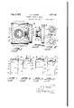
Figure 1 represents a sectional elevation of a four-cycle engine embodying the features of construction and improvements comprised in the present invention,
Figure 2, a section taken on the line 22, Figure 1,
Figure 3, a transverse section along the line 33, Figure 1,
Figure at, an elevation of the cam and fly wheel-pulley included in the construction,
Figures 5 and 6, sections taken along the lines 55 and 66 of Figure 4, respectively, and
Figures 7, 8, 9 and 10, diagrammatic skeleton views of the working parts of the engine showing different positions thereof in the cycle of operation of the engine.
The cylinder 5 of the engine is ribbed as at 6, for cooling purposes and it terminates at its lower end in a crank-case 7. The opposite end of the cylinder is closed by a head 8 provided with a beveled seat 9 for the intake valve 10 of the engine. A hollow boss 12 above the seat 9 connects with the carburetor of the engine or other source of motive fluid, as at 13.
The valve engaging the seat at the inner surface of the head, has a. stem 14 that projects through an opening at the end of the boss, axially alined with the valve seat. The stem has a rounded knob 15 engaged by a rocking lever 16, and a spring 17 coiled around the stem between the head and the knob, provides a. yielding medium to hold the valve to its seat.
The lever hereinbefore referred to, is fulcrumed upon a standard 18 fastened upon the head 8, one of its arms has a rounded extremity in engagement with the knob of the valve stem and the other armof the lever connects with a rod 19 comprised in the cam movement hereinafter to be described.
Fitted for reciprocation in the cylinder is the power piston 20 which by means of a rod 21 is connected with the wrist of the crank 22 on a crank shaft 23 supported in bearings at opposite sides of the crank case.
A combined fly wheel and pulley 24 and a cam-wheel 25 preferably made together in one piece, are mounted upon the shaft at one end thereof, the cam-wheel being inside the crank case and the pulley outside the same.
A shank 26 between the cam-wheel proper and the pulley is rotatably fitted in an opening in the side of the crank case.
The cam-wheel is constructed to effect four movements of the intake valve in every two revolutions of the crank shaft'a-s will hereinafter be described.
It has, for this purpose, two circumferential grooves 27 and 28 that intersect one another so that a tappet rod working in the grooves may pass from one to another at the end of each revolution of the shaft. The bottom surface of each groove represents the contact face engaged by the end of the tappet rod, the face of each groove having a low point A and a high point B, it being observed that each face is of substantially elliptical form.
The tappet rod 29 is, at its upper end, pivotally connected with a hollow head 32 which is slidably fitted in a. housing 31, and which is connected with the rod 19 on the rocker-lever 16 through the medium of a ball 33 seated in the bottom of a cavity of the head, and engaged by the concaved end of the rod.
It is apparent that the tappet rod in switching from one cam groove to another must necessarily twist and this twisting motion is permitted by the swivel connection between the bar and the lever effected by the ball and the rod.
Excessive lateral movement of the tappet rod is prevented by a rectangular lining in the housing 31, opposite sides of which are gaged by the edges of the tappet rod, as best shown in Figure 3.
Interposed between the power piston and the intake port of the cylinder is a floating piston 36, preferably composed of two sections 34 and 35. The upper section has a valve seat 37 adapted to be engaged by the intake valve which to this end has a beveled face 38 additional to that which engages the seat on the head of the cylinder. The two sections of the floating piston are hollow to admit motive fluid taken in past the valve 10, to the power piston. r
The upper or body section 34, has a circumferential groove and the lower section has an internal rim 39 extending into the groove of the other.
The section is flexible and made in the form of a split skirt so that it may freely expand into fluid-tight contact with the wall of the cylinder. A pin 40 on the cylinder wall, projecting into the space between the ends of the split skirt, prevents the shell from turn- The cylinder has two series of exhaust ports uncovered when the floating piston occupies its normal position at the end of the piston chamber and the other series being uncovered by the power piston when the latter is at the end of its power stroke.
The skirt 35 of the floating piston, has a series of openings 43 adapted to register in one position of the floating piston with an opening 44 in the piston wall occupied by the gap end of a spark plug 45 and to register in another position of the floating piston with the series of exhaust ports 41.-
The last mentioned ports communicate directly with the atmosphere, but the other series of ports open into a manifold 46 formed around the wall of the cylinder and provided with an outlet 47. A spring-pressed valve 48 controls the escape of the exhaust gases through the opening and prevents the intake of atmospheric air and the escape of motive fluid when the engine is not exhausting.
The automatic control of the communication between the exhaust ports and the atmosphere is an essential feature of the construction and greatly increases the efficiency thereof.
It is to be understood, however, that under certain conditions, the series of exhaust openings 42 may be entirely eliminated, in which case all the burnt gases are exhausted through the ports 41. The provision of two series of exhaust ports at different points, as shown in the drawings, provides for the complete expulsion of exhaust gases in the minimum of time.
In the operation of the engine, the valve 10 is moved to and from its seat 9 at the end of the cylinder at periodic intervals in the rotary movement of the cam shaft, the valve controls the passage of motive fluid through the floating piston to the power piston and it also effects an inward movement ofthe floating piston by engagement with the valve seat 37 thereof.
The floating piston-controls the exhaust through the ports 41, the power piston controls the exhaust of gases through the ports 42 and the spark plug is, as usual, connected in a circuit with a suitable turning device operating in conjunctiongwith the crank shaft.
A timing mechanism has been indicated at 49, but neither its circuit nor its connections have been illustrated in the drawings since they do not differ either in construction or relative arrangement from other engines at present in common use.
Premising that the parts are in the position illustrated in Figure 9, after a charge of motive fluid has been compressed in the space between the two pistons, it will be noted that both pistons are at the end of their outward strokes and in engagement with each other, the intake valve is in engagement with both its seats thereby closing all communication between the source of motive fluid and the cylinder, and the ports 43 in the skirt of the floating piston are in register with the spark plug 45 of the cylinder. At this point, the circuit of the spark plug is closed by the timing element and the spark produced at the gap of the plug ignites the charge between the pistons with the results that the power piston is driven outwardly to the position illustrated in Figure 10.
During the power stroke of the piston the valve 10 is separated from its seat by the cam movement and, by engagement with the valve seat of the floating piston, pushes the latter inwardly to a position in which its ports 43 are in register with the exhaust ports 41. The power piston has moved past the exhaust ports 42 and both series of ports are thus uncovered for the rapid exhaust of burnt gases during the return stroke of the power piston.
At the end of the return stroke of the power piston the two pistons and the valve are momentarily returned to their original position shown in Figure 9, but immediately thereafter, during subsequent outward movement of the piston, the valve is again separated from its seat in the end of the cylinder by the cam-movement, the floating piston is first pushed inwardly by the valve and then separated from the valve by the suction of the power piston and a fresh charge of fuel is taken in through the openings 9 and 37 of the cylinder and the floating piston into the combustion space between the two pistons.
This condition has been illustrated in Figure 7, it being understood that the valve 10 is during this part of the operation, not opened sufficiently to cause the floating piston to uncover the exhaust ports 41, and that the popvalve 48 prevents the escape of the charge through the exhaust ports.
Prior to the following inward movement of the power piston, depicted in Figure 8, the valve seat-opening 9 is closed by the cammovement, and the immediately following movement of the power piston compresses the charge between the pistons and again moves the floating valve to the original position illustrated in Figure 9, at which point the charge is fired.
Having thus described my improved internal combustion engine, it is to be understood that variations in the construction and arrangement of the parts described therein, may be made within the scope of the invention.
As stated before, the exhaust ports 42 may, under certain conditions, be eliminated, the high and low points of the cam may be formed at the sides of the grooves instead of at the bottom thereof, or the cam may be otherwise changed as long as it performs its particular function in eflecting a plurality of distinctive movements of one or more engine-valves during tw-o revolutions of the crank shaft.
The bar 30 of the cam may be made of resilient material to permit of its end following the pitch of the cam-grooves, in which case the ball joint may be omitted.
The intersectiong cam grooves make it possible to produce one or more periodic movements of a valve or other machine part during any two successive revolutions of the shaft on which it is mounted, but it will be apparent that if it is desired to have the movements occur between alternate periods of inactivity, one of the grooves may be devoid of motion-producing points for idle movement of the tappet rod while the other groove has the high and low points, as hereinbefore described.
lVhat I claim and desire to secure by Let ters Patent is:
1. In an internal combustion engine, a valve movement comprising a rotary wheel having intersecting grooves of different depths to provide cam faces, and a member adapted to follow the grooves and pass from one to another at their point of intersection during rotation.
2. In an internal combustion engine, a valve movement comprising a rotary shaft, :1 bearing for the shaft fastened on same, the bearing having intersecting cam grooves of different depths, and a tappet rod to follow the grooves and pass from one to another.
3. In an internal combustion engine, a valve movement comprising a rotary shaft, a cylindrical member concentrically mounted on the shaft and having intersecting grooves of different depths, an angular guide tube permanently mounted in close proximity to said member, and a flat faced tappet rod in the tube, disposed to follow the grooves and pass from one to another at their point of intersection, and adapted to be opposed in its movements by a face engaging a face of the tube.
nature.
CLOYD L. KINDER.
In testimony whereof I have aflixed my sigi V
Priority Applications (1)
| Application Number | Priority Date | Filing Date | Title |
|---|---|---|---|
| US314138A US1817153A (en) | 1928-10-22 | 1928-10-22 | Internal combustion engine |
Applications Claiming Priority (1)
| Application Number | Priority Date | Filing Date | Title |
|---|---|---|---|
| US314138A US1817153A (en) | 1928-10-22 | 1928-10-22 | Internal combustion engine |
Publications (1)
| Publication Number | Publication Date |
|---|---|
| US1817153A true US1817153A (en) | 1931-08-04 |
Family
ID=23218724
Family Applications (1)
| Application Number | Title | Priority Date | Filing Date |
|---|---|---|---|
| US314138A Expired - Lifetime US1817153A (en) | 1928-10-22 | 1928-10-22 | Internal combustion engine |
Country Status (1)
| Country | Link |
|---|---|
| US (1) | US1817153A (en) |
Cited By (5)
| Publication number | Priority date | Publication date | Assignee | Title |
|---|---|---|---|---|
| DE3610639A1 (en) * | 1985-04-04 | 1986-10-16 | Kawasaki Jukogyo K.K., Kobe, Hyogo | VALVE ROD FOR A FOUR-STROKE ENGINE |
| US4682573A (en) * | 1983-02-15 | 1987-07-28 | Kawasaki Jukogyo Kabushiki Kaisha | Valve gear for use in a four cycle engine |
| US4683847A (en) * | 1984-12-27 | 1987-08-04 | Kawasaki Jukogyo Kabushiki Kaisha | Valve system for overhead valve type four-cycle engine |
| US4697555A (en) * | 1985-04-05 | 1987-10-06 | Kawasaki Jukogyo Kabushiki Kaisha | Valve gear for four-cycle engine |
| FR2866065A1 (en) * | 2004-02-09 | 2005-08-12 | Robert Gabriel Tailhades | Internal combustion engine, has combustion chamber undergoing double variation of volume induced by alternative translation of piston to create four-strokes, where one variation acts through less elongation gaps close to top dead end |
-
1928
- 1928-10-22 US US314138A patent/US1817153A/en not_active Expired - Lifetime
Cited By (5)
| Publication number | Priority date | Publication date | Assignee | Title |
|---|---|---|---|---|
| US4682573A (en) * | 1983-02-15 | 1987-07-28 | Kawasaki Jukogyo Kabushiki Kaisha | Valve gear for use in a four cycle engine |
| US4683847A (en) * | 1984-12-27 | 1987-08-04 | Kawasaki Jukogyo Kabushiki Kaisha | Valve system for overhead valve type four-cycle engine |
| DE3610639A1 (en) * | 1985-04-04 | 1986-10-16 | Kawasaki Jukogyo K.K., Kobe, Hyogo | VALVE ROD FOR A FOUR-STROKE ENGINE |
| US4697555A (en) * | 1985-04-05 | 1987-10-06 | Kawasaki Jukogyo Kabushiki Kaisha | Valve gear for four-cycle engine |
| FR2866065A1 (en) * | 2004-02-09 | 2005-08-12 | Robert Gabriel Tailhades | Internal combustion engine, has combustion chamber undergoing double variation of volume induced by alternative translation of piston to create four-strokes, where one variation acts through less elongation gaps close to top dead end |
Similar Documents
| Publication | Publication Date | Title |
|---|---|---|
| US3084678A (en) | Internal combustion engine with shifting cylinders | |
| US3584610A (en) | Internal combustion engine | |
| US3446192A (en) | Four-cycle internal combustion engine | |
| US2983264A (en) | Cam engine valve means | |
| US2302442A (en) | Internal combustion engine | |
| US4658776A (en) | Rotary valve internal combustion engine | |
| US3388693A (en) | Two-cycle engine with charge pump therein | |
| US1904680A (en) | Radial cam type internal combustion engine | |
| US1817153A (en) | Internal combustion engine | |
| US1550643A (en) | Reciprocatory internal-combustion engine | |
| US2937631A (en) | High efficiency internal combustion engine | |
| US2937630A (en) | Compound internal combustion engine | |
| KR970021677A (en) | An internal combustion engine | |
| US1874195A (en) | Internal combustion engine | |
| US3729927A (en) | Two-cycle internal combustion engine | |
| US2344496A (en) | Internal combustion engine | |
| US1856348A (en) | Internal combustion engine | |
| US1670549A (en) | Internal-combustion engine | |
| US2428791A (en) | Engine | |
| US2445720A (en) | Opposed cylinder two-cycle engine | |
| US2215030A (en) | Multivane intake control valve | |
| US2089636A (en) | Internal combustion engine | |
| US3177856A (en) | Internal combustion engine | |
| US1726073A (en) | Engine | |
| US2004693A (en) | Single sleeve valve engine |