US1784587A - Coin-controlled vending machine - Google Patents
Coin-controlled vending machine Download PDFInfo
- Publication number
- US1784587A US1784587A US237045A US23704527A US1784587A US 1784587 A US1784587 A US 1784587A US 237045 A US237045 A US 237045A US 23704527 A US23704527 A US 23704527A US 1784587 A US1784587 A US 1784587A
- Authority
- US
- United States
- Prior art keywords
- disc
- coin
- vending machine
- outer face
- same
- Prior art date
- Legal status (The legal status is an assumption and is not a legal conclusion. Google has not performed a legal analysis and makes no representation as to the accuracy of the status listed.)
- Expired - Lifetime
Links
- 230000000295 complement effect Effects 0.000 description 13
- 238000010276 construction Methods 0.000 description 6
- 210000003811 finger Anatomy 0.000 description 6
- 210000001331 nose Anatomy 0.000 description 3
- 241000282472 Canis lupus familiaris Species 0.000 description 2
- 235000015218 chewing gum Nutrition 0.000 description 2
- 229940112822 chewing gum Drugs 0.000 description 2
- 235000019504 cigarettes Nutrition 0.000 description 2
- 235000009508 confectionery Nutrition 0.000 description 2
- 210000000887 face Anatomy 0.000 description 2
- 239000011521 glass Substances 0.000 description 2
- 239000007787 solid Substances 0.000 description 2
- RYGMFSIKBFXOCR-UHFFFAOYSA-N Copper Chemical compound [Cu] RYGMFSIKBFXOCR-UHFFFAOYSA-N 0.000 description 1
- 230000008901 benefit Effects 0.000 description 1
- 235000019506 cigar Nutrition 0.000 description 1
- 238000007599 discharging Methods 0.000 description 1
- 210000005069 ears Anatomy 0.000 description 1
- 230000005484 gravity Effects 0.000 description 1
- VKYKSIONXSXAKP-UHFFFAOYSA-N hexamethylenetetramine Chemical compound C1N(C2)CN3CN1CN2C3 VKYKSIONXSXAKP-UHFFFAOYSA-N 0.000 description 1
- 230000004048 modification Effects 0.000 description 1
- 238000012986 modification Methods 0.000 description 1
- 230000002459 sustained effect Effects 0.000 description 1
- 210000003813 thumb Anatomy 0.000 description 1
Images


Classifications
-
- G—PHYSICS
- G07—CHECKING-DEVICES
- G07F—COIN-FREED OR LIKE APPARATUS
- G07F11/00—Coin-freed apparatus for dispensing, or the like, discrete articles
- G07F11/46—Coin-freed apparatus for dispensing, or the like, discrete articles from movable storage containers or supports
- G07F11/50—Coin-freed apparatus for dispensing, or the like, discrete articles from movable storage containers or supports the storage containers or supports being rotatably mounted
- G07F11/54—Coin-freed apparatus for dispensing, or the like, discrete articles from movable storage containers or supports the storage containers or supports being rotatably mounted about vertical axes
Definitions
- One of the important objects of the present invention is to provide a coin controlled vend- 1 ing machine which includes a revoluble casing or magazine holder that carries a plurality of magazines which are adapted to contain various articles or commodities that are put up in package form, for example such as chewing gum and the like; the articles or commodities of one magazine being of a differentprice than the articles or commodities of another magazine whereby the machine is capable of Vending articles having diiferent sale prices.
- Another important object of the invention is to provide a master unit that is arranged centrally of the revoluble casing or magazine holder, coin controlled mechanism being associated with the master unit and adapted for cooperation with the ejector associated with each magazine whereby the selected article may be dispensed from the machine upon the deposit of the proper amount in the machine.
- a further object is to provide a change making mechanism for association with the master unit, and each of the magazines whereby the proper change will be returned to the purchaser or operator of the machine when a coin of a higher denomination than the cost of the selected article is inserted, each magazine carrying a change control unit that is so constructed as to return only the difference between the price of the article selected and a coin of a higher denomination inserted in the machine.
- a still further and important object of the present invention resides in the provision of means to prevent the operation of the ejector when a coin of a denomination less than the price of the article selected is inserted in the machine, the coin deposited being returned to the operator in such an instance, thereby preventing any loss being sustained by the customer.
- Another important object is to provide a means for prohibiting the actuation of the article delivery mechanism unless any one of the magazines is in direct alignment with the deliver chute, said locking means being automatica 1y released when one of the magazines is in proper position with respect to the delivery chute.
- a still further object is to provide a coin controlled vending machine of the above mentioned character which will at all times be positive and eflicient in its operation, the same belng further simple in constructlon, inexpensive, strong and durable and further well adapted to the purposes for which it is designed.
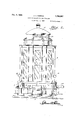
- Figure 1 is a front elevation of my improved coin controlled vending machine, a portion of the base being broken away.
- Figure 2 is a vertical sectional view therethrough the central or master unit being shown in elevation and looking at the front side thereof.
- Figure 3 is a top plan view of the machine, the ornamental top or cover being removed to illustrate the change control units carried by the article holding magazine and to further disclose the relation between the master unit and the sectional revoluble magazine holder or caslng.
- Figure 4 is an enlarged fragmentary view partly in section and partly in elevation, showing the actuating means for the change control unit as well as the means for effecting the actuation of an ejector provided for one of the change holding tubes, and further illustrating the several deflectors and coin guide chutes forming a part of the present invention.
- Figure 5 is a top plan of the coin controlled mechanism and the pivoted arms provided with finger engaging noses at their outer free ends for cooperation with certain parts of each of the change control units carried by Figure 7 is a sectional view through the pairs of coacting discs of the coin controlled -mechanism taken substantially at right angles to Figure 6.
- Figure 8 is a detail erspective view of one of the arms showing t e finger engagin nose at the outer forward end thereof and t e enlar ed looped portion at its opposite end.
- Figure 9 is a side elevation of one air of spaced complementary discs, one of said discs being partly broken away.
- Figures 10 and 11 are details of the discs showing the arrangement of the curved ribs on the inner opposed faces thereof.
- Figure 12 is an enlarged detail of the means for locking the article delivery mechanism in an inoperative position when the selected magazine is not in direct alinement with the delivery chute, the locking means being disclosed in a released position in this figure.
- Figure 13 is a view disclosing the slidable ejector plates provided for the several change holding tubes and the actuating levers associated therewith.
- Figure 14 is a detail perspective view of one of the pivoted levers associated with each slidable ejector for the change holding tubes.
- Fi ure 15 is a similar view of one of the slidafile links associated with the upper end of each of the pivoted levers.
- Figure 16 is a detail disclosing the hinged ejector plate provided for the open lower end of each article holding magazine, said ejector plate being shown in the act of discharging the lowermost package into the delivery chute; the spring controlled yoke or aw for holding the next lowermost package during the downward swinging movement of the hinged plate being shown in its operative position.
- Figure 17 is a detail perspective view of the package gripping yoke or jaw.
- Figure 18 is a vertical sectional view taken substantially on the line 18r-18 of Figure 19 looking in the direction of the arrows for illustrating the means to efiect the downward swinging movement of the hinged late provided for the upper coin receiving c ute.
- Figure 19 is a further illustration of said means.
- Figure 20 is a top plan view of the hinged plate actuating mechanism and also the package gripping yoke or jaw, the parts being shown in their inoperative position.
- Figure 21 is a front elevation of the change control unit that is adapted to be associated with the fifteen-cent article holding magazine.
- Figure 22 is a rear elevation thereof.
- Figure 23 is a vertical sectional view taken substantially on the line 23-23 of Figure 21.
- Figure 24 is a transverse section taken substantially on the line 24-24 of Figure 21.
- Figure 25 is a view similar to Figure 21, parts being removed and showin only two of the vertically slidingfive-cent ngers in a raised position as well as the complementary sliding plate in its raised position.
- Figure 26 is a similar view showing two other of the three five-cent fingers in their raised position, and the complementary plate associated therewith being also-in the raised position.
- Figure 27 is a similar view showing 'all three of the five-cent fingers raised and the complementary plates also raised whereby the vertically shding foot member of the change control unit is raised.
- Fi re 28 is a detail perspective view of one o the sliding bars and the pivoted dog associated therewith for cooperation with the vertically sliding fingers of the change control unit.
- Figure 29 is a similar view of the foot member forming a part of each change control unit.
- Figure 30 is a detail perspective view of one of the dogs associated with each change control unit which is provided with an enlar ed nose at its free end for cooperation wit the enlarged free end of the sliding links which are in turn associated with the change tube ejector operating levers.
- Figure 31 is a detail perspective view of one of the sliding fingers.
- Figure 32 as well as Figures 33 and 34 are detail perspective views of the difierent sliding plates associated with each change control unit.
- Figure 35 is a detail perspective view of one of the slidable ejectors provided for each change holding tube.
- Figure 36 is a detail of a modification of the change holding tubes and the ejector means associated therewith, the change tube in the present instance being adapted for vertical swinging movement while the ejector member is stationary.
- Figure 37 is a detail perspective view of the pivoted lever that is provided for effecting the swinging movement of the pivoted change holding tube.
- Figure 38 is a fragmentary detail of the lower end portion of one of the change holding tubes showing the diametrically opposed slots formed in the same to accommodate the forked ejector.
- Fi ure 39 is a sectional view taken substantially on the line 39-39 of Figure 36.
- Figure 40 is a detail perspective view of one of the forked stationary ejectors.
- Figure 41 is a detail of the gear carried by the horizontal shaft that is provided for actuating the coin controlled mechanism.
- the numeral 1 designates the base, and extending upwardly therefrom is the circular track 2.
- Ada ted for rotation on the base is the revolul fle casing or magazine holder designated generally by the numeral 3.
- the revoluble casin or magazine holder consists of a pair 0 complementary semi-circular sections 4 and 5, respectively, the same being connected together at their adjacent edges in any appropriate manner whereby the same can be easily and readily assembled or disassembled.
- the complementary sections of the revoluble casing or magazine holder 3 are assembled, the same will form a polygonal shaped structure in top plan as is clearly disclosed in F igure 3. It is however understood that I do not Wish myself limited to the particular shape of the casing or magazine holder.
- each section of the revoluble casing or magazine holder 3 Arranged on the inner side of each section of the revoluble casing or magazine holder 3 are a series of vertically disposed compartments or magazines 6. These magazines extend from the top of the casing to the bottom thereof and each side or face of the polygonal shaped casing is provided with the cut out portions 7. A glass panel 8 is disposed over each cut out portion on the inside of the casing. Suitable guides are provided for receiving and supporting the glass panels in position over the open front side of the respective compartmentsor magazine. This construction permits the merchandise to be displayed so that a prospective purchaser may rotate the casing until the desired article is disposed in vertical alinement with the delivery chute 9, the latter extending laterally from the base and the circular track 1 and 2, respectively.
- the merchandise to be vended by the present machine is preferably put up in package form, and by providing a number of magazines or compartments, various articles may be dispensed from the machine, such as chewing gum, cigarettes, cigars, candy and the like. Furthermore, the machine embodying my invention is capable of dispensing articles that sell at different prices as will be hereinafter more fully described.
- a laterally extending flange 10 is carried by the lower end portion of each of the complementary sections of the casing and the outer edge portion of these flanges is disposed downwardly as at 11.
- the lower edge portion of each of the complementary sec-- tions of the casing is furthermore so constructed at spaced intervals as to form depending brackets 12 that cooperate with the depending portion 11 of the lateral flange 10 to support the grooved rollers 13.
- the grooved rollers are adapted to travel on the upper ed 9 of the track 2, and as is clearly illustrated in Figure 2, the depending portion 11 is disposed outwardly of the track, while the depending brackets 12 are arranged inwardly of said track.
- a series of spaced notches 15 are formed in the lower edge of the depending portion 11 as is clearly illustrated in Figure 1. These notches are preferably arranged at the center of each of the article holding magazines or compartments and adapted for cooperation with these notches is a sprin pressed latch 16, the same being arranged for vertical sliding movement in a suitable housing 17 provided therefor on the outer side of the circular track 2. The upper end of this housing is open and the upper end of the sliding latch is depending portion 11 may readily and easily ride over the beveled upper free end of said latch.
- An expansible coil spring 18 is arranged within a housing 17 below the sliding latch and engages the bottom thereof for normally urging the same upwardly into engagement with the lower edge of the depending portion 11 and the notches 15 formed therein.
- the outer side of the housing 17 is provided with a longitudinal slot 19 through which extends a thumb engaging member 20 that is carried by the outer side of the latch 16 whereby said latch may be moved downwardly in its housing to disengage the same from the notched depending portion 11.
- the circular track that constitutes the rear portion of the housing is formed with an elongated slot 21 and extending therethrough is the upper curved end portion of a vertical arm 22. The upper curved end of this arm is secured to the latch for movement therewith whilethe lower end portion of this arm is slidable through a suitable bracket 23 arranged on the inside of the track 2. This is all clearly shown in Figure 12.
- this vertically movable arm 22 is operatively connected to the outer end of an elongated lever 24 that is fulcrumed intermediate its ends as at 25in a suitable bracket 26.
- the opposite end of this lever is operatively connected to the lower end of a vertically sliding toothed bar 27 that is guided in a guide bracket or housing 28 open beveled so that the lower edge of the llU at its respective ends, and which bracket or guide is secured in a stationary manner on one side of the frame 29 that forms a part of the master unit structure which will be specifically described later.
- a master unit designated generall by the numeral 32 the same comprising a rame heretofore referred to and desi ated by the numeral 29.
- This unit is rigi ly secured at itslower end on a suitable block 33 that is carried by the central portion of the base 1.
- a change control unit designated generally by the numeral 34 is associated with the inner face of the rear side of each article holding magazine 6, and the master unit 32 is so arranged with respect to these change control units 34 as not to interfere with the rotation of the sectional casing 3 whereby any one of the article holding magazines that may be selected can be properly positioned in alinement with the dellvery chute 9.
- the upper portion of the frame 29 formin a part of the master unit 32 extends beyon the top of the com lementary sections comprising the revolu ble casing or magazine holder 3, and into the cover 30.
- a solid block 35 Supported in the top of this frame 29 is a solid block 35, the same being formed with a series of longitudinally extending coin slots that are formed in the upper face of the block and extend from the forward to the rear end thereof. In the present instance, eight of such slots are provided. Three of the slots are so constructed as to receive only five-cent coins and these particular slots are denoted by the numeral 36.
- a similar number of slots are constructed to receive only ten-cent coins and these particular slots are denoted by the numeral 37.
- the other two slots formed in the upper face of this solid block 35 are constructed for receiving twenty-five cent and fifty-cent coins respectively, and the same are designated by the numerals 38 and 39, respectively.
- the rear en s of the coin slots formed in the block" 35 communicate with the coin chutes 4lvthat extend downwardly between the sides of the frame 29. Eight of such chutes are provided, and three of these chutes are adapted to cooperate with the three fivecent coin receiving slots 36. Three more of these chutes cooperate with the three tencent coin receiving slots 37 while the other two of the coin receiving chutes are adapted for cooperation with the twenty-five and fifty cent coin slots 38 and 39 respectively.-
- the block 35 is inclined downwardly toward its rear end whereby the coins entering the respective slots formed in the upper face thereof will by gravity enter the respective chutes 41.
- the lower ends of these chutes are adapted for cooperation with a master coin controlled mechanism, the construction of which will now be more specifically described.
- Said coin controlled mechanism comprises a pair of upper and lower plates 42 and 43 respectively, the same being secured together in the intermediate portion of the frame 29. These plates are formed with a series of transversely extending parallel spaced registering cut-out p0rt1ons44 and 45 respectively, as is clearly illustrated in Figures 4 and 5 of the drawings.
- the portions of the plates between the registering slots 01' cut out portions 44 and 45 are enlarged at the intermediate or central portion of the plates as indicated at 46 with reference more particularly to Figure 7
- the enlarged central portion 46 between each pair of registering slots is also slotted as illustrated at 47 in Figure 5.
- a relatively short shaft 48 is journaled for rotation between suitable bearings 49 arranged at one side of the frame 29 of said master unit 32.
- this particular shaft carries a disc 50 and the outer face of this disc has arranged thereon what may be termed a cam forming portion 51 the purpose of which will be hereinafter more full described.
- a similar disc 52 Cooperating with this particular disc is a similar disc 52, the same being provided on its outer face with a central sleeve 53. This sleeve is journaled for rotation in suitable bearings provided therefor by the central raised portions 46 of the upper and lower plates 42 and'43, respectively.
- a spur gear 54 is secured on the sleeve 53 for rotation therewith and is adapted for disposition through the registering slots 47 formed in the central raised ortions 46 as is further illustrated in Figure
- a disc 55 has formed on its outer face at the central portion thereof a cylindrical pro jection 56 that is fitted within the sleeve 53 of the adjacent disc 52 whereby said discs will rotate in unison.
- This particular disc 55 is arranged in the next adjacent pair of registering openings .44 and 45 formed in the upper and lower plates 42 and 43 respectively, and in the same openings there is arranged a coacting disc 57, the same being formed on its outer face with a central cylindrical shaft forming projection 58.
- the outer face of this particular disc is formed with a cam 59 similar to the cam 51 formed on the outer face of the beforementioned disc 50.
- This central shaft forming projection 58 fits within a sleeve 60 that is formed on the outer face of a disc 61.
- the disc 62 Cooperating with the disc 61 is the disc 62, and the outer face of this disc has formed thereon a sleeve similar to the sleeve formed on the outer face of the disc 52 for receiving the central shaft-like projection formed on the outer face of the next adjacent disc 63.
- These last two mentioned discs 62 and 63 are secured together for simultaneous rotation, but are located in different cut-out portions formed in the upper and lower plates.
- a spur gear 64 similar to the spur gear 54 is secured on the sleeve associated with the disc 62 and rotates therewith, the central raised portions of the plates between the discs 62 and 63 being slotted to accommodate this gear.
- a complementary disc 65 Arranged within the same cut out portion as the disc 63 is a complementary disc 65, the same being formed on its outer face with a central sleeve for receivin the central shaft forming projection form on the outer face of the next adjacent disc 66.
- the outer faces of these two discs are further formed with cams similar to the cams 51 and 59 formed on the discs 50 and 57 respectively, as well as the cam formed on the outer face of the disc 61.
- a complementary disc 67 Arranged within the same cut out portions in the plates 42 and 43 as the disc 66 is a complementary disc 67 and this disc is of substantially the same construction as the discs 55 and 63, the same being formed with a central shaft forming projection on its outer face which fits in a sleeve formed on the outer face of the next adjacent disc 68 in the same manner as the projection 56 fits in the sleeve 53 of the disc 52 so that the discs 67 and 68 will operate in unison.
- a spur gear 69 similar to the spur gears 54 and 64 is secured on the sleeve that is associated with the disc 68 and this gear rotates with these last mentioned pair of discs 67 and 68.
- Cooperating with the disc 68 is a disc 70 that is identical in construction with the disc 61 in that the outer face thereof is formed with a central sleeve, and with a cam similar to the cam formed on the outer face of the disc 61.
- a disc 71 is located in the next adjacent cut out portions formed in the u per and lower plates 42 and 43 and this disc 1 is provided on its outer face with a central shaft-like projection that enters the sleeve formed on the outer face of the adjacent disc 70 and also the outer face of this disc 71 is formed with a cam so that said disc is in realit tion as the isc 60.
- a complementary disc designated by the numeral 72 Arran ed within the same cut out portions in the p ates 42 and 43 as the disc 71 is a complementary disc designated by the numeral 72 and this disc is of the same construction as the disc 67 heretofore described, the same being formed with a central shaftlike projection on its outer face for cooperation with the central sleeve formed on the outer face of the next adjacent disc 73 which disc is of the same structure as the disc 68.
- These discs 72 and 73 are therefore adapted to rotate simultaneously and carried by the sleeve'that is associated with the disc 73 is the spur gear 74, the same being of the same structure as the aforementioned spur ears and also the-central raised portions 0 the plates are cut out to accommodate this last mentioned spur gear and this is clearly brought out in Flgure 7.
- the disc 75 which disc is formed on its outer face with a central enlarged shaft forming projection 76 similar .to the shaft 48 formed on the outer face of the first mentioned disc 50.
- This shaft 76 is supported in the opposite side of the frame 29 in suitable bearings 77 and furthermore the outer face of the last mentioned disc 75 is provided with a cam 78 similar to the cam 51 formed on the outer face of the disc 50.
- each pair of coacting discs Formed on the inner opposed faces of each pair of coacting discs are the curved ribs 9 and 80,- respectively. These ribs are so arranged as to provide an interfitting relation when the complementary discs are in position as shown in Fi re 7.
- the opposed ends of the series of ribs arranged on the inner face of each disc converge gradually toward the center so as to form the coin receiving pockets 81 and 82 at the top and bottom respectively of each pair of discs.
- a pocket construction of this character will prevent the accidental dis lacement of a coin when the latter has een discharged from its respective chute by gravit into the proper pocket.
- each pair of coacting discs are of such size as to be adapted to receive a coin of a predetermined denomination.
- These particular coin receiving pockets have heretofore been more fully described in the patent to Donathan #1,619,246, March 1, 1927.
Landscapes
- Physics & Mathematics (AREA)
- General Physics & Mathematics (AREA)
- Vending Machines For Individual Products (AREA)
Description
Dec. 9, 1930. J. H. FARRAR COIN CONTROLLED VENDING MACHINE Filed Dec. 1, 1927 l5 Sheets-Sheet 1 Inventor Dec. 9, 1930. J FARRAR 1,784,587
COIN CONTROLLED VENDING MACHINE Filed Dec. 1, 1927 15 Sheets-Sheet 2 l Ll arrai'f A liar/1 111' Dec. 9, 1930. J. H. FARRAR COIN CONTROLLED VENDING MACHINE l5 Sheets-Sheet 5 Filed Dec. 1, 1927 Inventor C]: f 7747;
J. H. FARRAR Dec. 9; 1930.
COIN CONTROLLED VENDING MACHINE l5 Sheets-Sheet 4 Filed Dec. 1, 1927 Dec. 9, 1930. FARRAR 1,784,587
COIN CONTROLLED VENDING MACHINE Filed Dec. 1, 1927 15 Sheets-Sheet 5 'I :67 J #Jrra 77 B @MMM Dec. 9, 1930. J FARRAR 1,784,587
COIN CONTROLLED VENDING MACHINE Filed Dec. 1, 1927 15 Sheets-Sheet 6 Inventor J jrra 7 B QM Dec. 9, 1930. l FARRAR 1,784,587
COIN CONTROLLED VENDING MACHINE Filed Dec. 1, 1921' 15 Shet's-Sheet 7 Inventor Zkrraw;
Azmrney Dec. 9, 1930. FARRAR 1,784,587
COIN CONTROLLED VENDING MACHINE Filed Dec. 1, 1927 l5 Sheeta-Sheec 8 M157. 12 I l J 20 lctn .g jyi/i Dec. 9, 1930. FARRAR 1,784,587
COIN CONTROLLED VENDING MACHINE Filed Dec. 1. 1927 15 Sheets-Sheet 9 In 'ventor Dec. 9, 1930.
Filed Dec. 1, 1927 15 Sheets-Sheet 10 E Q 7 o w M/ P W 7 W H 2 s fll I'Tm A? w H A 0 7 a 0 IL N M Q m (ML 2 2 7 w w m y 3 L Q 0 m 0 0 |w= d 0 Q. owl m 6/.600 9 flm w.
Inventor e]. flf'ar ra ,1,
. Q v fig Attorney Dec. 9, 1930. J FARRAR 1,784,587
COIN CONTROLLED VENDING MACHINE Filed Dec. 1, 1927 15 swag-sh 1 II III Z00 Inventor J fiffrrar;
Attorney Dec. 9, 1930.
J. H. FARRAR COIN CONTROLLED VENDING MACHINE Filed Dec.
o /90L F 15 Sheets-Sheet 12 B QM J. H. FARRAR Dec. 9, 1930.
COIN CONTROLLED VENDING MACHINE Filed Dec. 1, 1927 15 Sheets-Sheet 13 Invemar a7: MfaT/ut Attorney Dec. 9, 1930. J, FARRAR 1,734,587
COIN CONTROLLED VENDING MACHINE 15 Sheet-Sheet 14 Filed Dec. 1, 1927 Inventor Dec. 9, 1930. J. H. FARRAR COIN CONTROLLED VENDING MACHINE Filed Dec. 1, 1927 15 Sheets-Sheet l5 Irz venmr .ZZrra Liv 241w cigarettes, candy,
Patented Dec. 9, 1930 UNITED STATES PATENT OFFICE JOHN H. FARRAR, OF MEMPHIS, TENNESSEE, ASSIGNOR '10 STEPHEN J. GRAHAM, OF .TUCKERMAN, ARKANSAS 'COIN-CON'IROLLED VENDING MACHINE Application filed December 1, 1927. Serial No. 237,045.
5 W. F. Donathan No. 1,619,246, March 1, 1927,
it embodies a great many departures therefrom as will fully hereinafter appear.
One of the important objects of the present invention is to provide a coin controlled vend- 1 ing machine which includes a revoluble casing or magazine holder that carries a plurality of magazines which are adapted to contain various articles or commodities that are put up in package form, for example such as chewing gum and the like; the articles or commodities of one magazine being of a differentprice than the articles or commodities of another magazine whereby the machine is capable of Vending articles having diiferent sale prices.
Another important object of the invention is to provide a master unit that is arranged centrally of the revoluble casing or magazine holder, coin controlled mechanism being associated with the master unit and adapted for cooperation with the ejector associated with each magazine whereby the selected article may be dispensed from the machine upon the deposit of the proper amount in the machine. 0 A further object is to provide a change making mechanism for association with the master unit, and each of the magazines whereby the proper change will be returned to the purchaser or operator of the machine when a coin of a higher denomination than the cost of the selected article is inserted, each magazine carrying a change control unit that is so constructed as to return only the difference between the price of the article selected and a coin of a higher denomination inserted in the machine.
A still further and important object of the present invention resides in the provision of means to prevent the operation of the ejector when a coin of a denomination less than the price of the article selected is inserted in the machine, the coin deposited being returned to the operator in such an instance, thereby preventing any loss being sustained by the customer.
Another important object is to provide a means for prohibiting the actuation of the article delivery mechanism unless any one of the magazines is in direct alignment with the deliver chute, said locking means being automatica 1y released when one of the magazines is in proper position with respect to the delivery chute.
A still further object is to provide a coin controlled vending machine of the above mentioned character which will at all times be positive and eflicient in its operation, the same belng further simple in constructlon, inexpensive, strong and durable and further well adapted to the purposes for which it is designed.
Other objects'of the invention and advan tages thereof will'become apparent during the course of the following description.
In the accompanying drawings forming a part of this application, and in which like numerals indicate like parts through the same:
Figure 1 is a front elevation of my improved coin controlled vending machine, a portion of the base being broken away.
' Figure 2 is a vertical sectional view therethrough the central or master unit being shown in elevation and looking at the front side thereof.
Figure 3 is a top plan view of the machine, the ornamental top or cover being removed to illustrate the change control units carried by the article holding magazine and to further disclose the relation between the master unit and the sectional revoluble magazine holder or caslng.
Figure 4 is an enlarged fragmentary view partly in section and partly in elevation, showing the actuating means for the change control unit as well as the means for effecting the actuation of an ejector provided for one of the change holding tubes, and further illustrating the several deflectors and coin guide chutes forming a part of the present invention.
Figure 5 is a top plan of the coin controlled mechanism and the pivoted arms provided with finger engaging noses at their outer free ends for cooperation with certain parts of each of the change control units carried by Figure 7 is a sectional view through the pairs of coacting discs of the coin controlled -mechanism taken substantially at right angles to Figure 6.
Figure 8 is a detail erspective view of one of the arms showing t e finger engagin nose at the outer forward end thereof and t e enlar ed looped portion at its opposite end.
Figure 9 is a side elevation of one air of spaced complementary discs, one of said discs being partly broken away. v
Figures 10 and 11 are details of the discs showing the arrangement of the curved ribs on the inner opposed faces thereof.
Figure 12 is an enlarged detail of the means for locking the article delivery mechanism in an inoperative position when the selected magazine is not in direct alinement with the delivery chute, the locking means being disclosed in a released position in this figure.
Figure 13 is a view disclosing the slidable ejector plates provided for the several change holding tubes and the actuating levers associated therewith.
Figure 14 is a detail perspective view of one of the pivoted levers associated with each slidable ejector for the change holding tubes.
Fi ure 15 is a similar view of one of the slidafile links associated with the upper end of each of the pivoted levers.
Figure 16 is a detail disclosing the hinged ejector plate provided for the open lower end of each article holding magazine, said ejector plate being shown in the act of discharging the lowermost package into the delivery chute; the spring controlled yoke or aw for holding the next lowermost package during the downward swinging movement of the hinged plate being shown in its operative position.
Figure 17 is a detail perspective view of the package gripping yoke or jaw.
Figure 18 is a vertical sectional view taken substantially on the line 18r-18 of Figure 19 looking in the direction of the arrows for illustrating the means to efiect the downward swinging movement of the hinged late provided for the upper coin receiving c ute.
Figure 19 is a further illustration of said means.
Figure 20 is a top plan view of the hinged plate actuating mechanism and also the package gripping yoke or jaw, the parts being shown in their inoperative position.
Figure 21 is a front elevation of the change control unit that is adapted to be associated with the fifteen-cent article holding magazine.
Figure 22 is a rear elevation thereof.
Figure 23 is a vertical sectional view taken substantially on the line 23-23 of Figure 21.
Figure 24 is a transverse section taken substantially on the line 24-24 of Figure 21.
Figure 25 is a view similar to Figure 21, parts being removed and showin only two of the vertically slidingfive-cent ngers in a raised position as well as the complementary sliding plate in its raised position.
Figure 26 is a similar view showing two other of the three five-cent fingers in their raised position, and the complementary plate associated therewith being also-in the raised position.
Figure 27 is a similar view showing 'all three of the five-cent fingers raised and the complementary plates also raised whereby the vertically shding foot member of the change control unit is raised.
Fi re 28 is a detail perspective view of one o the sliding bars and the pivoted dog associated therewith for cooperation with the vertically sliding fingers of the change control unit.
Figure 29 is a similar view of the foot member forming a part of each change control unit.
Figure 30 is a detail perspective view of one of the dogs associated with each change control unit which is provided with an enlar ed nose at its free end for cooperation wit the enlarged free end of the sliding links which are in turn associated with the change tube ejector operating levers.
Figure 31 is a detail perspective view of one of the sliding fingers.
Figure 32 as well as Figures 33 and 34 are detail perspective views of the difierent sliding plates associated with each change control unit.
Figure 35 is a detail perspective view of one of the slidable ejectors provided for each change holding tube.
Figure 36 is a detail of a modification of the change holding tubes and the ejector means associated therewith, the change tube in the present instance being adapted for vertical swinging movement while the ejector member is stationary.
Figure 37 is a detail perspective view of the pivoted lever that is provided for effecting the swinging movement of the pivoted change holding tube.
Figure 38 is a fragmentary detail of the lower end portion of one of the change holding tubes showing the diametrically opposed slots formed in the same to accommodate the forked ejector.
Fi ure 39 is a sectional view taken substantially on the line 39-39 of Figure 36.
Figure 40 is a detail perspective view of one of the forked stationary ejectors, and
Figure 41 is a detail of the gear carried by the horizontal shaft that is provided for actuating the coin controlled mechanism.
In the drawings, with reference more particularly to Figures 1, 2, 8, 4 and 12, respectively, the numeral 1 designates the base, and extending upwardly therefrom is the circular track 2.
Ada ted for rotation on the base is the revolul fle casing or magazine holder designated generally by the numeral 3. In the present instance the revoluble casin or magazine holder consists of a pair 0 complementary semi-circular sections 4 and 5, respectively, the same being connected together at their adjacent edges in any appropriate manner whereby the same can be easily and readily assembled or disassembled. When the complementary sections of the revoluble casing or magazine holder 3 are assembled, the same will form a polygonal shaped structure in top plan as is clearly disclosed in F igure 3. It is however understood that I do not Wish myself limited to the particular shape of the casing or magazine holder.
Arranged on the inner side of each section of the revoluble casing or magazine holder 3 are a series of vertically disposed compartments or magazines 6. These magazines extend from the top of the casing to the bottom thereof and each side or face of the polygonal shaped casing is provided with the cut out portions 7. A glass panel 8 is disposed over each cut out portion on the inside of the casing. Suitable guides are provided for receiving and supporting the glass panels in position over the open front side of the respective compartmentsor magazine. This construction permits the merchandise to be displayed so that a prospective purchaser may rotate the casing until the desired article is disposed in vertical alinement with the delivery chute 9, the latter extending laterally from the base and the circular track 1 and 2, respectively.
The merchandise to be vended by the present machine is preferably put up in package form, and by providing a number of magazines or compartments, various articles may be dispensed from the machine, such as chewing gum, cigarettes, cigars, candy and the like. Furthermore, the machine embodying my invention is capable of dispensing articles that sell at different prices as will be hereinafter more fully described.
A laterally extending flange 10 is carried by the lower end portion of each of the complementary sections of the casing and the outer edge portion of these flanges is disposed downwardly as at 11. The lower edge portion of each of the complementary sec-- tions of the casing is furthermore so constructed at spaced intervals as to form depending brackets 12 that cooperate with the depending portion 11 of the lateral flange 10 to support the grooved rollers 13. The grooved rollers are adapted to travel on the upper ed 9 of the track 2, and as is clearly illustrated in Figure 2, the depending portion 11 is disposed outwardly of the track, while the depending brackets 12 are arranged inwardly of said track.
In order that the polygonal shaped casing may be rotated on the track, I provide a plurality of knobs or handles 14, the same being carried by the sections of the casing. Thus a person may grasp any one of the handles and rotate the polygonal shaped casing on the track in order to bring the magazine carrying the desired article into alinement with the delivery chute 9.
A series of spaced notches 15 are formed in the lower edge of the depending portion 11 as is clearly illustrated in Figure 1. These notches are preferably arranged at the center of each of the article holding magazines or compartments and adapted for cooperation with these notches is a sprin pressed latch 16, the same being arranged for vertical sliding movement in a suitable housing 17 provided therefor on the outer side of the circular track 2. The upper end of this housing is open and the upper end of the sliding latch is depending portion 11 may readily and easily ride over the beveled upper free end of said latch.
An expansible coil spring 18 is arranged within a housing 17 below the sliding latch and engages the bottom thereof for normally urging the same upwardly into engagement with the lower edge of the depending portion 11 and the notches 15 formed therein. The outer side of the housing 17 is provided with a longitudinal slot 19 through which extends a thumb engaging member 20 that is carried by the outer side of the latch 16 whereby said latch may be moved downwardly in its housing to disengage the same from the notched depending portion 11. v The circular track that constitutes the rear portion of the housing is formed with an elongated slot 21 and extending therethrough is the upper curved end portion of a vertical arm 22. The upper curved end of this arm is secured to the latch for movement therewith whilethe lower end portion of this arm is slidable through a suitable bracket 23 arranged on the inside of the track 2. This is all clearly shown in Figure 12.
The lower end of this vertically movable arm 22 is operatively connected to the outer end of an elongated lever 24 that is fulcrumed intermediate its ends as at 25in a suitable bracket 26. The opposite end of this lever is operatively connected to the lower end of a vertically sliding toothed bar 27 that is guided in a guide bracket or housing 28 open beveled so that the lower edge of the llU at its respective ends, and which bracket or guide is secured in a stationary manner on one side of the frame 29 that forms a part of the master unit structure which will be specifically described later. The pu ose ofthe slidable latch 16 and the other e ements cooperatively associated therewith will be pres-- Arranged centrally within the rotatable casing or magazine holder 3 is a master unit designated generall by the numeral 32, the same comprising a rame heretofore referred to and desi ated by the numeral 29. This unit is rigi ly secured at itslower end on a suitable block 33 that is carried by the central portion of the base 1.
' A change control unit designated generally by the numeral 34 is associated with the inner face of the rear side of each article holding magazine 6, and the master unit 32 is so arranged with respect to these change control units 34 as not to interfere with the rotation of the sectional casing 3 whereby any one of the article holding magazines that may be selected can be properly positioned in alinement with the dellvery chute 9.
The upper portion of the frame 29 formin a part of the master unit 32 extends beyon the top of the com lementary sections comprising the revolu ble casing or magazine holder 3, and into the cover 30.
Supported in the top of this frame 29 is a solid block 35, the same being formed with a series of longitudinally extending coin slots that are formed in the upper face of the block and extend from the forward to the rear end thereof. In the present instance, eight of such slots are provided. Three of the slots are so constructed as to receive only five-cent coins and these particular slots are denoted by the numeral 36.
A similar number of slots are constructed to receive only ten-cent coins and these particular slots are denoted by the numeral 37. The other two slots formed in the upper face of this solid block 35 are constructed for receiving twenty-five cent and fifty-cent coins respectively, and the same are designated by the numerals 38 and 39, respectively.
The forward ends of these slots cooperate with initial coin deposit slots 40 formed in in the block 35 for receiving five and ten cent coins respectively, there manifestly is a similar number of slots formed in the cover to cooperate with the respective slots in the block. Any suitable means may be rovided for properly identifying the respective slots 40 so that the customer will not make a mistake when operatin the machine;
The rear en s of the coin slots formed in the block" 35 communicate with the coin chutes 4lvthat extend downwardly between the sides of the frame 29. Eight of such chutes are provided, and three of these chutes are adapted to cooperate with the three fivecent coin receiving slots 36. Three more of these chutes cooperate with the three tencent coin receiving slots 37 while the other two of the coin receiving chutes are adapted for cooperation with the twenty-five and fifty cent coin slots 38 and 39 respectively.- The block 35 is inclined downwardly toward its rear end whereby the coins entering the respective slots formed in the upper face thereof will by gravity enter the respective chutes 41. The lower ends of these chutes are adapted for cooperation with a master coin controlled mechanism, the construction of which will now be more specifically described.
Said coin controlled mechanism comprises a pair of upper and lower plates 42 and 43 respectively, the same being secured together in the intermediate portion of the frame 29. These plates are formed with a series of transversely extending parallel spaced registering cut-out p0rt1ons44 and 45 respectively, as is clearly illustrated in Figures 4 and 5 of the drawings.
The portions of the plates between the registering slots 01' cut out portions 44 and 45 are enlarged at the intermediate or central portion of the plates as indicated at 46 with reference more particularly to Figure 7 The enlarged central portion 46 between each pair of registering slots is also slotted as illustrated at 47 in Figure 5. A relatively short shaft 48 is journaled for rotation between suitable bearings 49 arranged at one side of the frame 29 of said master unit 32.
The inner end of this particular shaft carries a disc 50 and the outer face of this disc has arranged thereon what may be termed a cam forming portion 51 the purpose of which will be hereinafter more full described. Cooperating with this particular disc is a similar disc 52, the same being provided on its outer face with a central sleeve 53. This sleeve is journaled for rotation in suitable bearings provided therefor by the central raised portions 46 of the upper and lower plates 42 and'43, respectively.
A spur gear 54 is secured on the sleeve 53 for rotation therewith and is adapted for disposition through the registering slots 47 formed in the central raised ortions 46 as is further illustrated in Figure A disc 55 has formed on its outer face at the central portion thereof a cylindrical pro jection 56 that is fitted within the sleeve 53 of the adjacent disc 52 whereby said discs will rotate in unison.-
This particular disc 55 is arranged in the next adjacent pair of registering openings .44 and 45 formed in the upper and lower plates 42 and 43 respectively, and in the same openings there is arranged a coacting disc 57, the same being formed on its outer face with a central cylindrical shaft forming projection 58. The outer face of this particular disc is formed with a cam 59 similar to the cam 51 formed on the outer face of the beforementioned disc 50. This central shaft forming projection 58 fits within a sleeve 60 that is formed on the outer face of a disc 61. Cooperating with the disc 61 is the disc 62, and the outer face of this disc has formed thereon a sleeve similar to the sleeve formed on the outer face of the disc 52 for receiving the central shaft-like projection formed on the outer face of the next adjacent disc 63. These last two mentioned discs 62 and 63 are secured together for simultaneous rotation, but are located in different cut-out portions formed in the upper and lower plates. A spur gear 64 similar to the spur gear 54 is secured on the sleeve associated with the disc 62 and rotates therewith, the central raised portions of the plates between the discs 62 and 63 being slotted to accommodate this gear.
Arranged within the same cut out portion as the disc 63 is a complementary disc 65, the same being formed on its outer face with a central sleeve for receivin the central shaft forming projection form on the outer face of the next adjacent disc 66. The outer faces of these two discs are further formed with cams similar to the cams 51 and 59 formed on the discs 50 and 57 respectively, as well as the cam formed on the outer face of the disc 61. Arranged within the same cut out portions in the plates 42 and 43 as the disc 66 is a complementary disc 67 and this disc is of substantially the same construction as the discs 55 and 63, the same being formed with a central shaft forming projection on its outer face which fits in a sleeve formed on the outer face of the next adjacent disc 68 in the same manner as the projection 56 fits in the sleeve 53 of the disc 52 so that the discs 67 and 68 will operate in unison.
A spur gear 69 similar to the spur gears 54 and 64 is secured on the sleeve that is associated with the disc 68 and this gear rotates with these last mentioned pair of discs 67 and 68. Cooperating with the disc 68 is a disc 70 that is identical in construction with the disc 61 in that the outer face thereof is formed with a central sleeve, and with a cam similar to the cam formed on the outer face of the disc 61. A disc 71 is located in the next adjacent cut out portions formed in the u per and lower plates 42 and 43 and this disc 1 is provided on its outer face with a central shaft-like projection that enters the sleeve formed on the outer face of the adjacent disc 70 and also the outer face of this disc 71 is formed with a cam so that said disc is in realit tion as the isc 60.
Arran ed within the same cut out portions in the p ates 42 and 43 as the disc 71 is a complementary disc designated by the numeral 72 and this disc is of the same construction as the disc 67 heretofore described, the same being formed with a central shaftlike projection on its outer face for cooperation with the central sleeve formed on the outer face of the next adjacent disc 73 which disc is of the same structure as the disc 68. These discs 72 and 73 are therefore adapted to rotate simultaneously and carried by the sleeve'that is associated with the disc 73 is the spur gear 74, the same being of the same structure as the aforementioned spur ears and also the-central raised portions 0 the plates are cut out to accommodate this last mentioned spur gear and this is clearly brought out in Flgure 7.
Complementary to the disc 73 is the disc 75 which disc is formed on its outer face with a central enlarged shaft forming projection 76 similar .to the shaft 48 formed on the outer face of the first mentioned disc 50. This shaft 76 is supported in the opposite side of the frame 29 in suitable bearings 77 and furthermore the outer face of the last mentioned disc 75 is provided with a cam 78 similar to the cam 51 formed on the outer face of the disc 50.
Formed on the inner opposed faces of each pair of coacting discs are the curved ribs 9 and 80,- respectively. These ribs are so arranged as to provide an interfitting relation when the complementary discs are in position as shown in Fi re 7. The opposed ends of the series of ribs arranged on the inner face of each disc converge gradually toward the center so as to form the coin receiving pockets 81 and 82 at the top and bottom respectively of each pair of discs. A pocket construction of this character will prevent the accidental dis lacement of a coin when the latter has een discharged from its respective chute by gravit into the proper pocket. It is of course to e understood that the coin receiving pockets formed in each pair of coacting discs are of such size as to be adapted to receive a coin of a predetermined denomination. These particular coin receiving pockets have heretofore been more fully described in the patent to Donathan #1,619,246, March 1, 1927.
As is further illustrated in Figure 7, the lower ends of the several coin delivery chutes 41 are positioned directly above the coin reof the same identical construc-
Priority Applications (1)
| Application Number | Priority Date | Filing Date | Title |
|---|---|---|---|
| US237045A US1784587A (en) | 1927-12-01 | 1927-12-01 | Coin-controlled vending machine |
Applications Claiming Priority (1)
| Application Number | Priority Date | Filing Date | Title |
|---|---|---|---|
| US237045A US1784587A (en) | 1927-12-01 | 1927-12-01 | Coin-controlled vending machine |
Publications (1)
| Publication Number | Publication Date |
|---|---|
| US1784587A true US1784587A (en) | 1930-12-09 |
Family
ID=22892117
Family Applications (1)
| Application Number | Title | Priority Date | Filing Date |
|---|---|---|---|
| US237045A Expired - Lifetime US1784587A (en) | 1927-12-01 | 1927-12-01 | Coin-controlled vending machine |
Country Status (1)
| Country | Link |
|---|---|
| US (1) | US1784587A (en) |
Cited By (1)
| Publication number | Priority date | Publication date | Assignee | Title |
|---|---|---|---|---|
| US2639207A (en) * | 1947-06-04 | 1953-05-19 | Samuel M Kaufman | Vending machine |
-
1927
- 1927-12-01 US US237045A patent/US1784587A/en not_active Expired - Lifetime
Cited By (1)
| Publication number | Priority date | Publication date | Assignee | Title |
|---|---|---|---|---|
| US2639207A (en) * | 1947-06-04 | 1953-05-19 | Samuel M Kaufman | Vending machine |
Similar Documents
| Publication | Publication Date | Title |
|---|---|---|
| US2258912A (en) | Stamp dispensing machine | |
| US3795345A (en) | Product dispensing apparatus | |
| US4087020A (en) | Article vending machine having rotary storage compartments | |
| US2435526A (en) | Multiple compartment vending machine | |
| US3800932A (en) | Coin operated card vending machine | |
| US3819087A (en) | Article-dispensing apparatus | |
| US1968500A (en) | Commodity vending machine | |
| US1809693A (en) | Bottle vending machine | |
| US3709404A (en) | Vending machine | |
| US1784587A (en) | Coin-controlled vending machine | |
| US1839480A (en) | Vending machine | |
| US2285931A (en) | Vending machine | |
| US2100752A (en) | Merchandising machine and apparatus | |
| US1936515A (en) | Vending machine | |
| US1697306A (en) | Vending apparatus | |
| US2180326A (en) | Vending machine | |
| US1821501A (en) | Vending machine | |
| US1260578A (en) | Vending-machine. | |
| US1697537A (en) | Coin-controlled machine | |
| US1871000A (en) | Vending machine | |
| US1345499A (en) | Coin-controlled vending-machine | |
| US2078490A (en) | Match vending machine | |
| US1191032A (en) | Coin-controlled collar-vending machine. | |
| US1959688A (en) | Vending machine | |
| US1726924A (en) | Vending machine |