US1784530A - Combination fire-alarm and watchman's recording box - Google Patents
Combination fire-alarm and watchman's recording box Download PDFInfo
- Publication number
- US1784530A US1784530A US9829A US982925A US1784530A US 1784530 A US1784530 A US 1784530A US 9829 A US9829 A US 9829A US 982925 A US982925 A US 982925A US 1784530 A US1784530 A US 1784530A
- Authority
- US
- United States
- Prior art keywords
- shaft
- spring
- contacts
- circuit
- watchmans
- Prior art date
- Legal status (The legal status is an assumption and is not a legal conclusion. Google has not performed a legal analysis and makes no representation as to the accuracy of the status listed.)
- Expired - Lifetime
Links
- 230000007246 mechanism Effects 0.000 description 64
- 230000033001 locomotion Effects 0.000 description 9
- 239000011810 insulating material Substances 0.000 description 3
- 238000010276 construction Methods 0.000 description 2
- 238000009877 rendering Methods 0.000 description 2
- 230000011664 signaling Effects 0.000 description 2
- 230000001276 controlling effect Effects 0.000 description 1
- 238000010586 diagram Methods 0.000 description 1
- 238000004519 manufacturing process Methods 0.000 description 1
- 230000007935 neutral effect Effects 0.000 description 1
- 230000001105 regulatory effect Effects 0.000 description 1
- GXPHKUHSUJUWKP-UHFFFAOYSA-N troglitazone Chemical compound C1CC=2C(C)=C(O)C(C)=C(C)C=2OC1(C)COC(C=C1)=CC=C1CC1SC(=O)NC1=O GXPHKUHSUJUWKP-UHFFFAOYSA-N 0.000 description 1
- NWONKYPBYAMBJT-UHFFFAOYSA-L zinc sulfate Chemical compound [Zn+2].[O-]S([O-])(=O)=O NWONKYPBYAMBJT-UHFFFAOYSA-L 0.000 description 1
Images


Classifications
-
- G—PHYSICS
- G07—CHECKING-DEVICES
- G07C—TIME OR ATTENDANCE REGISTERS; REGISTERING OR INDICATING THE WORKING OF MACHINES; GENERATING RANDOM NUMBERS; VOTING OR LOTTERY APPARATUS; ARRANGEMENTS, SYSTEMS OR APPARATUS FOR CHECKING NOT PROVIDED FOR ELSEWHERE
- G07C1/00—Registering, indicating or recording the time of events or elapsed time, e.g. time-recorders for work people
- G07C1/20—Checking timed patrols, e.g. of watchman
Definitions
- the principal object of the; present invention is to obviate the disadvantages referred to and to provide an improved combined signal transmitting mechanism of the character described.
- Another object of-the invention is to provide an apparatus of the character mentioned embodying a minimum number of parts and avoiding duplication of operative mechanism to as greata n extent as practicable. 1 further object is to simplify the construction of such apparatus so that econonly of manufacture will be promoted and ease of assembly and repair of the same will be facilitated. Further objects of the invention will appear in the course of the following description; To the accomplishment of the foregoing and related ends, said invention, then, consists of the means hereinafter fully described and particularly pointed out in the claims. I p
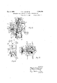
- Fig. 1 is a front elevation of thetransmitting mechanism, the portion shown'to the left being the lower, portion of the mechanism when the same is installed in its case;
- Fig. 2 is a sectional view of the apparatus shown in Fig. 1, taken along the line 22 shown in Fig. 4, looking in the'direction of'the arrows;
- Fig. 3 is a View similar to Fig. 2,,taken along the line 3-8 shown in Fig. 4, lookmg in the direction of the arrows; Flg. 4 1s a 17, 1925.. Serial 110.3,829.
- Fig. 5 is a rear elevation of the mechanisn'i shown in Fig. 1, the portion shown at the right being the lower portion of said apparatus when installed in the casing;
- Figs. 6 and 7 are sectional views of the mechanism shown in Fig. 4, taken along the lines 66and 77 of Fig. 4, looking in the direction of the arrows;
- Fig. 8 is a top plan view of the switch contacts and associatedsupporting members;
- Fig. 9 is a transverse sectional view taken along the line 9-9 shown in Fig. 3; and Fig. 10 is adiagrammatic view of the circuit connections. for the combination fire alarm' and watchmens recording boxes. j
- the apparatus comprises a supporting frame- 1 see Fig. 4), having a, front and back plate 2, 3, secured to each other by means of spacing bars 4.
- a pair of spindles 5, 6, are mounted in said frame and have their forward ends projecting from the front plate.
- One of these spindles 5 has secured to its outer end a pull lever 7 and when actuated is adapted to set the mechanism for sending in fire alarm.
- the other spindle 6 has pinned to its outer end a sleeve 8, (see also Figs.
- the fire alarm is designed torepeat the sig nal a number of times, in the apparatus shown, the signal beingrepcated four times, while the watchmans signal is intended to besent but once.
- the spindle 6, as is shown in Fig. 9, is journaled in a. spring shaft 12, said shaft carrying a spring 13' and being formed with gear teeth l4,'and the outerend of the tubular spring shaftis formed with a slot 20' on its upper side to receive the lug f the sleeve 8pinned to the outer end of said spindle (3.
- L washer 21 abuts a shoulder adjacent the gear 14 and serves to position the spring 13 against the rearward face of the front plate.
- a sleeve, provided with a ratchet 22, is pinned to the spring shaft with the ratchet abutting the rearward face of the gear 14. Adjacent the ratchet the sleeve ispr'ovided with a cylindrical'bearing 23 for a large gear 24, which is held in position by means of a collar 25.
- Tlie'same pin 26 which secures the sleeve to the spring shaft also holds the collar in position.
- the movementstop 15 see Figs; 4 and 7) is provided with a rearwardly 'extendii g pin 27 which lies within a groove 28 extending across the shunt circuit cam 29 which is 'positioned adjacent to the" movement stop on the opposite side of the collar 17*of the spindle 6 and has a reduced forward portion 30 of cylindrical shape.
- Rearwardl'y of the shunt circuit cam, the hub-31' of the code wheels 32, 33 is rotatably supported upon the spindle 6 and is held against the endof ⁇ the ⁇ shunt circuit cam by means of a set screw 34 in the end of said spindle.
- hub is provided with a driving gear 35 at its forward end, and at its rearward end has a reduced portion upon which an insulating collar 36 is mounted, said insulating collar serving as the hub for the code wheels, which ai'e'spaced from each other by a disc v37 or insulating material, Each. code wheel is secured to the spacing disc by means of screws or escutcheon pins 38, which extend through said disc in opposite directions alternately acent the circumferential portion of said ad insulating disc;
- the idler gear is of sufiicient width to engage the teeth of said gear 35 irrespective of its transverse ad ustnient,'when the watchmans code wheel is shifted beneath the innermost pair of contact fingers, wh ch w1ll be hereinafter dein the spring shaft 12 with relation to their lug 9 may be regulated.
- annular plate is provided, said plate being formed with a notch 56 in alignment with the lug 9 and a segmental recess -1 i '57 opposite thereto. As is shown in Fig. 9,
- the lug 9 is normally in engagement with said notch in the plate 55 and the spindlet is prevented from being rotated.
- the spindle 6 is pressed inwardly, the lug 9 is moved into the slot 20, and the lug 10' s broughtinto alignment with the segmental recess 57 and thespindle may be turned in one direction until the lug 10 abuts the end opposite the end'of the segmental recess with which it was first in contact.
- the watchmans code Wheel .32 will be moved away from the frame and brought beneath a pair of contact fingers 61, 62,forming the termiiials of tlieis eparate circuit for sending the ize v V
- the terminals referred to are mounted (see Figs. 5 to 7) upon v w an insulating support comprising an inter- 1 the pull lever.
- the spr ng13 is of the clock mediate block 63 secured to the back plate 3 and an upper andlower insulating plate 64,
- test lever 69 engaged at its free end within a notch 70 formed transversely of a terminal member 71 of insulating material which is mounted upon a test key shaft'72 (see Fig. 1) which projects through the front plate of the frame.
- the outer end 73 of the test key shaft is adapted to be engaged by a key and is prefelably formed of triangular shape, as shown in Fig. 1 of the drawing.
- the test key shaft is providedwith a laterally extending pin 74:, to the end of which a coil spring 75 is secured.
- the opposite end of the coil spring is anchored to a pin 68 set-in the forward face of the front plate at approximately the center thereof, and two guard pins 58, .59, are positioned adjacent the test'key shaft, one on either side thereof, to limit the movement of the test shaft through contact of the lateral pin with one or the other 'of said guard pins.
- test shaft When turned in one directionithe test shaft is thus adapted to open the contacts above the fire alarm code wheel at any time when it is desired to test the circuit. And when turned in the other direction, thetest shaft occasions the lifting of the contacts clear of the code wheel, after which the box mechanism may be tested without disturbing the circuit. On removing the key from the test shaft, spring 75 returns the test shaft to neutral position.
- the insulating block 63 directly supports the upper and lower shunt circuitcontacts 76, 77.
- the lower of said contacts carries a fsh'oe 78 of insulating material which is adapted to ride upon the cam- 29 heretofore described.
- the transmitting of the. fire alarm signal rotates the cam to close the shunt circuit. This prevents interference with the sending of fire alarm signals from alarm boxes further removed from the'central station when a box nearerthereto is operating.
- a large gear 81 is mounted which, through the gear 79 on the shaft 80 drives the escapement wheel 90.
- a pallet 82 engages the teeth of theescapement wheel in the'usual manner and retards the operation of the mechanism.
- the pallet shaft 83 has a sectional vane 84, having weights 85 at the outer ends. 1.
- the apparatus thusfar described willserve to actuate the watchmans signal.
- mechanism for actuating the fire alarm signal' comprises mechanism placed in advance of the mechanism heretofore described.v
- a large gear 97 is mounted, being journaled upon a bearing shoulder formed on the ratchet sleeve 91.
- a collar 98 is engaged over the rearward portion of said sleeve and is provided with a flange 99 which-bears against the gear, said collar being pinned to the sleeve andspindle.
- the gear carries on its forward side a pin 101 upon which a pawl 102 is mounted. The end of the pin is notched Projecting rearwardly from the flange 99, a pin 105- is provided, against which one end of the hook lever return spring 106 bears.
- the body of said spring is coiled about the collar between the flange and the back plate,
- the rat cartend pawl will thus be engaged in when the pull lever is actuated. Said lever,
- the watchmans key is engaged over the squared end 11 of the sleeve 8 which is pinnedjto the spindle 6.
- the sleeve, and spindle are then pressedtoward the back plate which clears end of the segmental recess to that with which it was first in contact, and'the movement is released to send the signal through the gear train connecting with the drive gear 35 on the code wheel hub 31 vVhen the spindle is pressed inwardly, the watchmans code wheel 32 will likewise be moved inwardly-and be brought from an idle position to a position beneath the contact fingers 61, 62.
- the fire alarm code wheel 63 by the same movement will be brought out of alignment with its spring contact fingers 66, 67.
- the pull lever 7 is moved in a clockwise direction, which turns the spindle 5 with its sleeve 91, carrying a ratchet wheel 92 pinned tothe spindle.
- the are of movement of the spindle 5 is defined by means of the pins 95, 96 set into the inner face of the front plate which are contacted with by means of a pin 94 set into the forward face of the ratchet. through its single tooth 93 engages the free end of the pawl 102 which is pressed downwardly by the spring 107 when the parts are in their normal position.
- the pawl 102 is carried on the large gear 97 which is rotated by the downward movement of the pull lever and through'the engagement of the teeth on its circumference it serves to rotate the spring shaft 12 through the gear 14 storing sufficient tension in the spring 13 to drive the fire alarm indicator code wheel four complete revolutions through the pawl 42, gear 24, the teeth of the ratchet 22 and the intermediate train of gears, identical with the gear train driving the watchmans code wheel throughthe' hub 31 and driving gear 35.
- The-fire alarm code wheel 33' is normally positioned beneath the contact fingers 66, 6'? while the watchmans code wheel 32 is normally out of alignment with its contactfingers 61, 62.
- the fire alarm signal maybe sent without lat erally moving the spindle 6 and itsassoci'ated mechanism.
- the watchmanls signal cannot be sent for the reason that the slot, 20 is moved out of ahgnm'ent with the lug '9 and prevents the spindle 6 from being forced inwardly into operative; relations with the spring shaft 12.
- theparts will be restored to their original position.
- Fig. 10 there are shown three combination watchmens and fire alarm boxes, the code wheels being indicated diagrammatically.
- 'lhewatclnnans circuit as 1in di'cated, connects with the spring contact fin gcrs above each of the watchmans code Wheels and said contacts are normally closed, such code wheels thus being in series connection.
- a relay there is included in the watchmans circuit a relay, and
- the watchmans code wheel is spaced closely adjacent the fire alarm code wheel and normally lies between the twopairs of contacts and out'of alignment with the watchmans circuit terminals. YVhem-however, the spindleo is pressed rearwardly. through the engagement of the .watchinans key withthe end of the spindle, the watchmans code wheel .is
- the C11'CLl1tCO1'll3aCt-S are normally closed.
- V T mans code-wheel 1S mounted upon the same l/Vhen, however, through the pull lever or the 1 watchmans key the mechanism is set for operation, the appropriate code wheel will I be 'placed in alignment with the proper circuit terminals and theteeth on the-periphery thereof willsuccessively separate the contacts, thereby sending in the alarm.
- shunt contacts are normally open. However, when the fire alarm transmitting mechanism' is in operation the shunt circuit will be closed through the action of the cam 29, Which will prevent signals being transmitted over the fire alarm circuit from a box further removed from the central station.
- the watchmans circuit has no shunt circuit, and when the watchmanscode wheel is in transmitting position the reduced portion of the cam sleeve will be brought beneath the shunt circuit shoe 7 8 and no shunt circuit closing action will take place. It is obvious, however, that if desired a separate shunt circuit for the watchmens circuit could be provided.
- the fire alarm circuit serves to actuate a series of gongs through the operation of a Prelay, whilethe watchmans circuit is connected with a relay which actuates a tape punch register.
- the particular signaling or recording means employed at the central station forms nopart of the present invention and it is obvious that any desired signaling de-" vice may be utilized.
- a, set of contact elements connected in a first circuit, a set of contact elements connected in a second circuit, and mechanism for actuating said respective sets ofcontacts to transmit distinctive signals over said circuits comprising an axially shiftable shaft, coding mechanism carried by said-shaft and normally disposed in cooperable relation With said first set of contacts. only, a motor for driving said contact mechanism, means for energizing said motor, separate means for energizing said motor and for simultaneously shifting said shaft to move said coding mechanism into cooperate-relation with said second set of contacts only, and means for holding said shaft in shifted position throughout a complete operative cycle of the device.
- a set of contact elements connected in a first circuit, a set of contact elements connected in, a second circuit, and mechanism for actuating said respective sets. of contacts to transmit distinctive signals over said circuits, comprising an axially shiftable shaft, coding in shifted position throughout a complete 7 operative cycle of the device.
- a set of contact pointsconnected in a first circuit a set of contact points connected in a second circuit,and mechanism for actuating said re-. spectivc sets of contacts to transmit distinctive signals over said circuits, comprising coding mechanism cooperable With said first set of contacts, coding mechanism cooperable With said second set of contacts, means for operating said coding mechanisms, and a plurality of means selectively operable to energize said operating means, one of said last-named means being rigidly connected. to said coding mechanisms and being shiftable to determine the alignment of said coding mechanisms'with said respective contacts.
- a set of'contact elements connected in a first circuit, a set of contact elements connected in a second circuit, and mechanism for actuating said respective sets of contacts, to transmit distinctive signals over said circuits; comprising coding mechanism normally in cooperable relation with said-first set of contacts, coding mechanism normally out ofcooperable relation with said second set ofcontacts, means for operating said coding mechanism, and a plurality of means selectivelyoperable to energize said operating means, one of said lastnamed means carrying 'said second coding mechanism being shiftable to move the same into cooperable relation with said second set' mechanism's, a plurality of means selectively operable to energize said operating means, one of said energizing means having a rigid connection with said second coding mechanism and being 'operableto move the same into cooperable relation with sa d's aid second set of contacts, and means associated with said coding mechanism establishing said shunt circuit only when the other of said en ergizing means is operated.
- Iri adevice of the class described a first set of contact points, and a second set of contact points, coding mechanism normally n cooperable relation with said first set of conout of cooperable relation with said second set of contacts, a terminal compr s ng a portion of a shunt circuit carried ad acent said coding mechanisms, contact means associate with said coding-mechanisms, and cooperabie with said shunt contact for establishing sa d shunt circuit, and means for shifting said secondcodingmechanism into cooperable relation with said second set of contacts simultaneously rendering said shunt contact means ineffective.
- first set of contacts only means connecting said motor to drive said coding mechanism, a contact member connected in a shunt circuit, another contact member connected n such shunt circuit and a cam carried by said shaft and coopei'able with one of sa d shunt contact members, attimes, to establsh such shunt circuit, means fonenerg zing s aidmotor, and means for shifting said shar tlongttudinally to move said coding mechanism into cooperable relation with said second set of contacts only and to rend'ersuch cam ineil'eo tive to establish said shunt circuit.
- a first set of contacts a second set of contacts, a motor, a longitudinally shiftable shaft.
- coding mechanism carried by said shaft, and normally in coopei'able relation with said set of contacts only, means connecting said with said alarm 30 tacts', a second coding mechanism normally.
- a first set of contacts a second set of con t acts, a motor, a longitudinally shiftable shaft, a code wheel carried by said shaft and normally in cooperative relation with said 61' of contacts and to render said cam member ineffective to establish said shunt circuit.
- a first set of c0n'tac'ts,'a second set of contacts a motor, a longitudinally shiftable shaft, acode wheel carried by said shaft and normally in cooperative relation with said first set of contacts, a secondcode wheel carried by said shaft and normally out of cooperative relation with said second set of contacts, means connecting said motor to drive said code wheels, a contact member connected in a shunt circuit, a second contact member connected in such shunt circuit and a.
- An apparatus of the character described having in combination, terminals of apiuraiit-y of circuits, a longitudinally shiftable shaft, coding mechanism carried by said shaft and normally in cooperable relation "with one set of said terminals only, said shaft bein shittabie to move said coding'meehaother contact member connected in such shuntnism into cooperable relation with another set of said terminals only, a motor, means connecting said motor to drive said coding mechanism including a sleeve rotatably mounted on said shaft, said sleeve being geared to said motor, and means on said shaft adapted When said shaft is shifted, to cause said shaft and sleeve to rotate together.
- An apparatus of the character described having in combination, terminals of a plurality of circuits, a longitudinally shiftable shaft, coding mechanism carried by said shaft and normally in cooperable relation with one set of said terminals only, said shaft being shiftable to move said coding mechanism into cooperable relation with another set of said terminals only, a motor, means connecting said motor to drive said coding mechanism including a sleeve rotatably mounted on said shaft and geared to said motor, means on said shaft adapted when said shaft is shifted, to cause said shaft and sleeve to rotate together, and means cooperable With said last-named means when said shaft has been shifted to hold said shaft in shifted position throughout a complete operative cycle of said apparatus.
- An apparatus of the character described having in combination, terminals of a plurality of circuits, a longitudinally shiftable shaft, coding mechanism carried by said shaft and normally in cooperable relation with one set of said terminals only, said shaft being shiftable to move said coding mechanism into cooper-able relation with another set of said terminals only, a motor, means con necting said motor to drive said coding mechanism including a sleeve rotatably mounted on said shaft and geared to said motor, means on said shaft adapted When said shaft is shifted, to cause said shaft and sleeve to ro tate together, means cooperable With said last-named means when said shaft has been shifted to hold said shaft in shifted position throughout a complete operative cycle of said apparatus, and means for returning said shaft to normal position upon completion of the cycle.
- An. apparatus of the character de scribed having in. combination, terminals of a plurality of circuits, a longitudinally shiftableshaft, a pair of code wheels carried by said shaft, said code Wheels ieing spaced apart by a distance differing from the space beiu'eei'i said. respective sets of terminals, a motor, means connecting said motor to drive said code wheels including a sleeve rotatable with respect to said shaft, said sleeve being provided with a notch at its one end, a collar pinned to said shaft, a lug on said collar,
- An apparatus of the character dc scribed having in combination a tubular shaft, a second shaft reciprocably mounted in said tubular shaft, said tubular shaft being rotatable With respect to said second shaft, a plurality of code Wheels pinned to said second shaft, a plurality of spring fingers projecting over said second shaft, means for moving said second shaft axially to bring one of said code Wheels beneath a selected spring linger, a separate electric circuit adapted to be connected and disconnected through each of said spring fingers, means engaging said tubular shaft for driving said code Wheels, and single means for energizing said driving means and con.- trolling the alignment of one of said code Wheels With respect to one of said spring fingers.
- An apparatus of the character described having in combination a tubular shaft, a second. shaft reciprocably mounted in said tubular shaft, said tubular shaft being rotatable with respect to said second shaft, a plurality of code wheels pinned to said sec ond shaft, a plurality of spring fingers projecting over said second shaft, means for moving said second shaft axially to bring one of sald code Wheels beneath a selected spring finger, a separate electric circuit adapted to be connected and disconnected through each of said spring fingers, means engaging said tubular shaft for drivingsaid code Wheels, single means for energizing said driving means and'contro-lling the alignment of one of said code Wheels With respect to one of said spring fingers, and means preventing operation of said last-named means to energize said driving means Without aligning said one code wheel with its respective spring fingers.
- An apparatus of the character described having in combination terminals of a plurality of electric circuits, automatically operated means selectively operable for intermittently opening and closing said respective circuits at said terminals, a spring motor for operating said means, means for energizing said motor to a predetermined degree for actuating one of said automatically operated means, means for energizingsaid motor to a predetermined and different degree for actuating another of said automati cally operated means, and separate means for rendering each of'said energizing means inoperative for energizing said motor during such automatic operation after energization of said motor by any One of said energizing means.
Landscapes
- Physics & Mathematics (AREA)
- General Physics & Mathematics (AREA)
- Connection Of Motors, Electrical Generators, Mechanical Devices, And The Like (AREA)
Description
Dec. 9, 1930.
F. B. LOVE ET AL COMBINATION FIRE ALARM AND WATCHMAN'S RECORDING BOX Filed Feb. 1'7, 1925 4 Sheets-Sheet l INVENTORS .yl'mzc'zls B. Lore 04 y Baycz 62711772. in M r 2 ATTORNEYS Dec. 9, 1930. .F. 8. LOVE ET AL 1,784,530
COMBINATION FIRE ALARM AND WATCHMANS RECORDING BOX FiledFeb. 1'7, 5 4 Sheets-Sheet 3 INVENTORJ ji'azzczls 5 Love 4/11/- A TTORNEYvS 1930. F. B. LOVE ET AL 1,734,530
COMBINATION FIRE ALARM AND WATCHMANS RECORDING BOX Filed Feb. 1'7, 1925 4 Sheets-Sheet 4 Q Q E V) -S :2 L 2 a u 3 U g & Q &' k v; Q X L 0 Q COMB/ ATION WATC/YMAN AND IRE ALARM 80 56 JIOOBl/J NJV7V 37/1 INVENTORS JZ'QIZCI'J Lo ve 4/14 4/099? t zLv w y Bo d/[62 112 12 Patented Dec. 9, 1930 PAT E FFHC FRANCIS B. LOVE AND BOYD H. SMITH, OF SHELBY, OHIO, ASSIGNOBS TO THE AUTO- CALL COMPANY, OF SHELBY, OHIO, A CORPORATION OF OHIO V COMBINATION FIRE4ALARM Ann WATCHMANS nnoonnrne, BOX
Application filed February ing boxes. More particularly it comprises a transmitting mechanism and associated circuits for sending from a single box distinctive signals for watchmens recording and fire alarm purposes. It has heretofore been proposed to combine a transmitting mechanism for watchmens signals with fire alarm signals, but in some instances such apparatus was complicated in construction and difficult to maintain in adjustment and repair under conditions of severe service.
. The principal object of the; present invention is to obviate the disadvantages referred to and to provide an improved combined signal transmitting mechanism of the character described. Another object of-the invention is to provide an apparatus of the character mentioned embodying a minimum number of parts and avoiding duplication of operative mechanism to as greata n extent as practicable. 1 further object is to simplify the construction of such apparatus so that econonly of manufacture will be promoted and ease of assembly and repair of the same will be facilitated. Further objects of the invention will appear in the course of the following description; To the accomplishment of the foregoing and related ends, said invention, then, consists of the means hereinafter fully described and particularly pointed out in the claims. I p
The annexed drawingsand the following description setforth in detail certain mechanism embodying the invention, such disclosed means constituting, however, but one of various mechanical forms in which the principle of the invention may be used.
In said annexed draW1ngs:
, Fig. 1 is a front elevation of thetransmitting mechanism, the portion shown'to the left being the lower, portion of the mechanism when the same is installed in its case; Fig. 2 is a sectional view of the apparatus shown in Fig. 1, taken along the line 22 shown in Fig. 4, looking in the'direction of'the arrows; Fig. 3 is a View similar to Fig. 2,,taken along the line 3-8 shown in Fig. 4, lookmg in the direction of the arrows; Flg. 4 1s a 17, 1925.. Serial 110.3,829.
view of the mechanism shown in F 1, as-
seen from the left-hand side of said figure;
Fig. 5 is a rear elevation of the mechanisn'i shown in Fig. 1, the portion shown at the right being the lower portion of said apparatus when installed in the casing; Figs. 6 and 7 are sectional views of the mechanism shown in Fig. 4, taken along the lines 66and 77 of Fig. 4, looking in the direction of the arrows; Fig. 8 is a top plan view of the switch contacts and associatedsupporting members;
Fig. 9 is a transverse sectional view taken along the line 9-9 shown in Fig. 3; and Fig. 10 is adiagrammatic view of the circuit connections. for the combination fire alarm' and watchmens recording boxes. j
As is clearlyshown inthe drawing, the apparatus comprises a supporting frame- 1 see Fig. 4), having a, front and back plate 2, 3, secured to each other by means of spacing bars 4. A pair of spindles 5, 6, are mounted in said frame and have their forward ends projecting from the front plate. One of these spindles 5 has secured to its outer end a pull lever 7 and when actuated is adapted to set the mechanism for sending in fire alarm. The other spindle 6 has pinned to its outer end a sleeve 8, (see also Figs. 1 and 9), carrying a pair of lugs 9, 10, and'having a squared end 11, which isadaptedto be engaged by a watchmans key, and, through the rotation of the spindle, place the mechanism under tension to send in the watchnians signal. The fire alarm is designed torepeat the sig nal a number of times, in the apparatus shown, the signal beingrepcated four times, while the watchmans signal is intended to besent but once. 1
The spindle 6, as is shown in Fig." 9, is journaled in a. spring shaft 12, said shaft carrying a spring 13' and being formed with gear teeth l4,'and the outerend of the tubular spring shaftis formed with a slot 20' on its upper side to receive the lug f the sleeve 8pinned to the outer end of said spindle (3.
j of engagement with the slot on the spring shaft.
1. L washer 21 abuts a shoulder adjacent the gear 14 and serves to position the spring 13 against the rearward face of the front plate. A sleeve, provided with a ratchet 22, is pinned to the spring shaft with the ratchet abutting the rearward face of the gear 14. Adjacent the ratchet the sleeve ispr'ovided with a cylindrical'bearing 23 for a large gear 24, which is held in position by means of a collar 25. Tlie'same pin 26 which secures the sleeve to the spring shaft also holds the collar in position.
The movementstop 15 see Figs; 4 and 7) is provided with a rearwardly 'extendii g pin 27 which lies within a groove 28 extending across the shunt circuit cam 29 which is 'positioned adjacent to the" movement stop on the opposite side of the collar 17*of the spindle 6 and has a reduced forward portion 30 of cylindrical shape. Rearwardl'y of the shunt circuit cam, the hub-31' of the code wheels 32, 33, is rotatably supported upon the spindle 6 and is held against the endof {the} shunt circuit cam by means of a set screw 34 in the end of said spindle. The
hub is provided with a driving gear 35 at its forward end, and at its rearward end has a reduced portion upon which an insulating collar 36 is mounted, said insulating collar serving as the hub for the code wheels, which ai'e'spaced from each other by a disc v37 or insulating material, Each. code wheel is secured to the spacing disc by means of screws or escutcheon pins 38, which extend through said disc in opposite directions alternately acent the circumferential portion of said ad insulating disc;
The large gear 'with a stud 41, upon which is mounted a pawl 42 pressed by means of a spring 43 into engagement with the teeth of the ratchet 22 whereby the rotation ofsaidlarge gear'in a clockwise direction iseii'ected whenever the clock spring is placed under 'tensionthrough theuse either of the watchmans key or of spring type and has its inner end engaged with a spring pin 44 formed on the spring shaft. Its outer end is looped about the adja- 24 (see Fig. 3) is provided watchmans code signal.
46, 47, forming part of the train for actuating the code wheels through the medium of an idler gear 48 supported upon a 1311149 in engagement with theteeth of the gear 35 on the code wheel hub. The idler gear is of sufiicient width to engage the teeth of said gear 35 irrespective of its transverse ad ustnient,'when the watchmans code wheel is shifted beneath the innermost pair of contact fingers, wh ch w1ll be hereinafter dein the spring shaft 12 with relation to their lug 9 may be regulated. At the point where the spring shaft 19/1310] ect's through the front plate, an annular plate is provided, said plate being formed with a notch 56 in alignment with the lug 9 and a segmental recess -1 i '57 opposite thereto. As is shown in Fig. 9,
the lug 9 is normally in engagement with said notch in the plate 55 and the spindlet is prevented from being rotated. When, however, through the use of the watchmans key the spindle 6 is pressed inwardly, the lug 9 is moved into the slot 20, and the lug 10' s broughtinto alignment with the segmental recess 57 and thespindle may be turned in one direction until the lug 10 abuts the end opposite the end'of the segmental recess with which it was first in contact. During such motion of, the spindle the for- 1 ward edge of the lug 9 will be engaged behind the edge of the annular plate and will hold thespindleinwardly and engaged with the spring shaft 12 until the lug 9 once more is moved into alignment with the notch 56, when the coil spring 19 will force the same outwardly to its original position. Theamount of movement thus permitted is just suiiicient to rotate the code wheel one revolution and thereby t-i'ansmit'the watchmans code signal one time, 1' i j During the operation justdescribed, wherei in the spindle 6 is held in its inward position,
the watchmans code Wheel .32 will be moved away from the frame and brought beneath a pair of contact fingers 61, 62,forming the termiiials of tlieis eparate circuit for sending the ize v V The terminals referred to are mounted (see Figs. 5 to 7) upon v w an insulating support comprising an inter- 1 the pull lever. The spr ng13 is of the clock mediate block 63 secured to the back plate 3 and an upper andlower insulating plate 64,
When turned in one directionithe test shaft is thus adapted to open the contacts above the fire alarm code wheel at any time when it is desired to test the circuit. And when turned in the other direction, thetest shaft occasions the lifting of the contacts clear of the code wheel, after which the box mechanism may be tested without disturbing the circuit. On removing the key from the test shaft, spring 75 returns the test shaft to neutral position.
The insulating block 63 directly supports the upper and lower shunt circuitcontacts 76, 77. The lower of said contacts carries a fsh'oe 78 of insulating material which is adapted to ride upon the cam- 29 heretofore described. The transmitting of the. fire alarm signal rotates the cam to close the shunt circuit. This prevents interference with the sending of fire alarm signals from alarm boxes further removed from the'central station when a box nearerthereto is operating.
Upon the shaft 45 (see Figs. 2 and 3) a large gear 81 is mounted which, through the gear 79 on the shaft 80 drives the escapement wheel 90. A pallet 82 engages the teeth of theescapement wheel in the'usual manner and retards the operation of the mechanism. The pallet shaft 83 has a sectional vane 84, having weights 85 at the outer ends. 1.
The apparatus thusfar described willserve to actuate the watchmans signal. The
mechanism for actuating the fire alarm signal'comprises mechanism placed in advance of the mechanism heretofore described.v
It comprises the spindle 5 adapted to be actuated by the hook lever 7 which is secured to its squared forward end 87 by means of a retaining screw 88.. i A sleeve 91, .provided with a ratchet wheel 92 having a single tooth 98, is pinned to the spindle 5. From the forward face of the ratchet a pin 94; projects, said pin being adapted to contact witha pair of pins 95, 96, setinto theinner face ofthe front plate,which thus define the arc of movement of the spindle 5.
. Immediately behind the ratchet wheel a large gear 97 is mounted, being journaled upon a bearing shoulder formed on the ratchet sleeve 91. A collar 98 is engaged over the rearward portion of said sleeve and is provided with a flange 99 which-bears against the gear, said collar being pinned to the sleeve andspindle. The gear carries on its forward side a pin 101 upon which a pawl 102 is mounted. The end of the pin is notched Projecting rearwardly from the flange 99, a pin 105- is provided, against which one end of the hook lever return spring 106 bears. The body of said spring is coiled about the collar between the flange and the back plate,
and thence extends about the spacing bar 1, upon which the end of the clock spring is looped, as heretofore described. The free end 107 of said spring is positioned above the lower end of the pawl.
The ratchetand pawl will thus be engaged in when the pull lever is actuated. Said lever,
however, bodily moves the ratchet wheel 92 and gear wheel 97 and thus moves the pawl.
from beneath the end 107 of the spring, the pressure on the pull lever thereafter maintaining the engagement of the pawl and ratchet. When the pull lever is released, the pawl spring 103 raises the lower end of the pawl. Further actuation of the pull lever thereafter will be ineffective to retard or in any way interfere with sending of the fire alarm code the full number of times for which the mechanism is arranged, inasmuch as the pawl will be; held clear of the ratchet until its nose rides underthe spring 107 as the.-movement rotates, whichresets the pawl in engagement with the ratchet.
To send/a .watchmans signal, the watchmans key is engaged over the squared end 11 of the sleeve 8 which is pinnedjto the spindle 6. The sleeve, and spindle are then pressedtoward the back plate which clears end of the segmental recess to that with which it was first in contact, and'the movement is released to send the signal through the gear train connecting with the drive gear 35 on the code wheel hub 31 vVhen the spindle is pressed inwardly, the watchmans code wheel 32 will likewise be moved inwardly-and be brought from an idle position to a position beneath the contact fingers 61, 62. The fire alarm code wheel 63 by the same movement will be brought out of alignment with its spring contact fingers 66, 67. VVhen'the watchmans code wheel has been driven a full revolution, the lug 9 will have moved back to its originalposition in alignment with the notch 56' and the coil spring 19 will then force the lug and its associated parts outwardly,disengaging the lug 9 from the slot 20 of the spring shaft 12, and locking the lug in the notch 56.
To send the fire alarm signal, the pull lever 7 is moved in a clockwise direction, which turns the spindle 5 with its sleeve 91, carrying a ratchet wheel 92 pinned tothe spindle. The are of movement of the spindle 5 is defined by means of the pins 95, 96 set into the inner face of the front plate which are contacted with by means of a pin 94 set into the forward face of the ratchet. through its single tooth 93 engages the free end of the pawl 102 which is pressed downwardly by the spring 107 when the parts are in their normal position. The pawl 102 is carried on the large gear 97 which is rotated by the downward movement of the pull lever and through'the engagement of the teeth on its circumference it serves to rotate the spring shaft 12 through the gear 14 storing sufficient tension in the spring 13 to drive the fire alarm indicator code wheel four complete revolutions through the pawl 42, gear 24, the teeth of the ratchet 22 and the intermediate train of gears, identical with the gear train driving the watchmans code wheel throughthe' hub 31 and driving gear 35. The-fire alarm code wheel 33'is normally positioned beneath the contact fingers 66, 6'? while the watchmans code wheel 32 is normally out of alignment with its contactfingers 61, 62. Thus the fire alarm signal maybe sent without lat erally moving the spindle 6 and itsassoci'ated mechanism. After the pull leveris moved totensionspring 13, the watchmanls signal cannot be sent for the reason that the slot, 20 is moved out of ahgnm'ent with the lug '9 and prevents the spindle 6 from being forced inwardly into operative; relations with the spring shaft 12. After'the fire alarm signal has been transmitted four times, theparts will be restored to their original position.
When the watchmans key is inserted: and is operated to rotate the sleeve -11 to wind the spring'13, engagementofthe teethld on said sleeve with the teeth-on jthe gear 97 causes rotation of saidgear in a clockwise direction. Such rotation, of course, moves thefpawl102 The ratchet out of contact with the retaining spring 107 and permits the pawl spring 103 to rotate said pawl in a clockwise direc'tion'about its pivot, thus moving the pawlend outof the path of the single tooth 93 of the ratc'hetwheel 92.
Consequently, operation of the fire lever 7 after actuation of the mechanism by the watchmans key and before the watchinans code has been completed will haveno efi'ect upon the mechanism. a
In Fig. 10 there are shown three combination watchmens and fire alarm boxes, the code wheels being indicated diagrammatically. 'lhewatclnnans circuit, as 1in di'cated, connects with the spring contact fin gcrs above each of the watchmans code Wheels and said contacts are normally closed, such code wheels thus being in series connection. There is included in the watchmans circuit a relay, and
anauxiliary line to a tape punch register.
through said relay from a battery. As indicated, the fire alarm and w-atchmans circuits are entirely separatel :lVhile the watchshaft with the fire alarm code-wheel, SttlCl=. .lvices are never in operation at the same time and the mechanism prevents thesending of the watchmans signal when the firealarm' signal is being transmitted. This is provided for through the. arrangement that the slot 20 in the spring shaft 12 will be out of alignment-withthe'lug 9 of the sleeve Swhen the fire alarm signal is'being transmitted. The watchmans code wheel is spaced closely adjacent the fire alarm code wheel and normally lies between the twopairs of contacts and out'of alignment with the watchmans circuit terminals. YVhem-however, the spindleo is pressed rearwardly. through the engagement of the .watchinans key withthe end of the spindle, the watchmans code wheel .is
brought 'into' alignment with said terminals and the firealarm code wheel is moved to an intermediate position outof contact with the firealarm circuit terminals;
The C11'CLl1tCO1'll3aCt-S are normally closed.
V T mans code-wheel 1S mounted upon the same l/Vhen, however, through the pull lever or the 1 watchmans key the mechanism is set for operation, the appropriate code wheel will I be 'placed in alignment with the proper circuit terminals and theteeth on the-periphery thereof willsuccessively separate the contacts, thereby sending in the alarm. The
shunt contacts are normally open. However, when the fire alarm transmitting mechanism' is in operation the shunt circuit will be closed through the action of the cam 29, Which will prevent signals being transmitted over the fire alarm circuit from a box further removed from the central station. The watchmans circuit has no shunt circuit, and when the watchmanscode wheel is in transmitting position the reduced portion of the cam sleeve will be brought beneath the shunt circuit shoe 7 8 and no shunt circuit closing action will take place. It is obvious, however, that if desired a separate shunt circuit for the watchmens circuit could be provided.
It is possible to employ the same code Wheel for actuating the contacts of each circuit where the signals to be sent are identical in character. The reception of such signals, however, would be upon separate indicating devices and thus no confusion would result as to the character of thesignal. g V
In the circur diagram shown in Fig. 10 the fire alarm circuit serves to actuate a series of gongs through the operation of a Prelay, whilethe watchmans circuit is connected with a relay which actuates a tape punch register. The particular signaling or recording means employed at the central station forms nopart of the present invention and it is obvious that any desired signaling de-" vice may be utilized.
Other modes of applying the principle of our inventionmay be employed instead of the one explained, change being made as regards the mechanism herein disclosed, provided the means stated by any of the following claims orthe equivalent of such stated means be employed. 7 i
Ne therefore particularly point out and distinctly claim as ourinvention 1. In a device of the classdescribed, a, set of contact elements connected in a first circuit, a set of contact elements connected in a second circuit, and mechanism for actuating said respective sets ofcontacts to transmit distinctive signals over said circuits, comprising an axially shiftable shaft, coding mechanism carried by said-shaft and normally disposed in cooperable relation With said first set of contacts. only, a motor for driving said contact mechanism, means for energizing said motor, separate means for energizing said motor and for simultaneously shifting said shaft to move said coding mechanism into cooperate-relation with said second set of contacts only, and means for holding said shaft in shifted position throughout a complete operative cycle of the device.
2. In a device of the class described, a set of contact elements connected in a first circuit, a set of contact elements connected in, a second circuit, and mechanism for actuating said respective sets. of contacts to transmit distinctive signals over said circuits, comprising an axially shiftable shaft, coding in shifted position throughout a complete 7 operative cycle of the device.
3. In a device of the class described, a.
set of contact elements connected in a first circuit, a setof contact elements connected in a second circuit, and mechanism for actuating said respective sets of contacts to trans mit distinctive signals over said circuits, comprising an axially shiftable shaft, coding mechanism carried by said shaft and normal ly disposed in cooperable relation With said first set of contacts only, a motor for driving said contact mechanism, means for energize ing said motor, separate'means for energizing said motor and for simultaneously shifting said shaft to move said coding mechanism into cooperable relation With said sec- 'ond set of contacts only, and means cooperable with said last-named means forholding said shaft in shifted position throughout a complete operative cycle of the device, and automatic means for returning said shaft to normal position upon completion of such cycle.
' 4-. In a device of the class described, a set of contact pointsconnected in a first circuit, a set of contact points connected in a second circuit,and mechanism for actuating said re-. spectivc sets of contacts to transmit distinctive signals over said circuits, comprising coding mechanism cooperable With said first set of contacts, coding mechanism cooperable With said second set of contacts, means for operating said coding mechanisms, and a plurality of means selectively operable to energize said operating means, one of said last-named means being rigidly connected. to said coding mechanisms and being shiftable to determine the alignment of said coding mechanisms'with said respective contacts.
5.. Ina device of the class described, a set of'contact elements connected in a first circuit, a set of contact elements connected in a second circuit, and mechanism for actuating said respective sets of contacts, to transmit distinctive signals over said circuits; comprising coding mechanism normally in cooperable relation with said-first set of contacts, coding mechanism normally out ofcooperable relation with said second set ofcontacts, means for operating said coding mechanism, and a plurality of means selectivelyoperable to energize said operating means, one of said lastnamed means carrying 'said second coding mechanism being shiftable to move the same into cooperable relation with said second set' mechanism's, a plurality of means selectively operable to energize said operating means, one of said energizing means having a rigid connection with said second coding mechanism and being 'operableto move the same into cooperable relation with sa d's aid second set of contacts, and means associated with said coding mechanism establishing said shunt circuit only when the other of said en ergizing means is operated. I a
Iri adevice of the class described, a first set of contact points, and a second set of contact points, coding mechanism normally n cooperable relation with said first set of conout of cooperable relation with said second set of contacts, a terminal compr s ng a portion of a shunt circuit carried ad acent said coding mechanisms, contact means associate with said coding-mechanisms, and cooperabie with said shunt contact for establishing sa d shunt circuit, and means for shifting said secondcodingmechanism into cooperable relation with said second set of contacts simultaneously rendering said shunt contact means ineffective. I
8. In a device of the character described, a
I first set of contacts, a second set of contacts,
a motor, a longitudinally shiftable shaft, coding mechanism carried by said shaft, and
normally in cooperable relation \Vlth. sai
first set of contacts only, means connecting said motor to drive said coding mechanism, a contact member connected in a shunt circuit, another contact member connected n such shunt circuit and a cam carried by said shaft and coopei'able with one of sa d shunt contact members, attimes, to establsh such shunt circuit, means fonenerg zing s aidmotor, and means for shifting said shar tlongttudinally to move said coding mechanism into cooperable relation with said second set of contacts only and to rend'ersuch cam ineil'eo tive to establish said shunt circuit. I I
9. In a device of, the character described, a first set of contacts,a second set of contacts, a motor, a longitudinally shiftable shaft. coding mechanism carried by said shaft, and normally in coopei'able relation with said set of contacts only, means connecting said with said alarm 30 tacts', a second coding mechanism normally.
motor to drive said coding mechanism, a contact member connected in a shunt circuit, an-
circuit and a cam carried by said shaft and cooperable with one of said shunt contact members, vat times, to establish such shunt circuit, means for energizing said motor, means for shifting said shaft longitudinally to move said coding mechanism into cooperable relation with said second set of contacts onlyiand to render said cam ineffective to establish such shunt circuit, andmeans for holding said shaft in shifted position throughout a complete operative cycle of the device.
10. In a device of the characterdescribed,
a first set of contacts,a second set of con t acts, a motor, a longitudinally shiftable shaft, a code wheel carried by said shaft and normally in cooperative relation with said 61' of contacts and to render said cam member ineffective to establish said shunt circuit.
11. In a device of the character described, a first set of c0n'tac'ts,'a second set of contacts, a motor, a longitudinally shiftable shaft, acode wheel carried by said shaft and normally in cooperative relation with said first set of contacts, a secondcode wheel carried by said shaft and normally out of cooperative relation with said second set of contacts, means connecting said motor to drive said code wheels, a contact member connected in a shunt circuit, a second contact member connected in such shunt circuit and a. cam carried by said shaft and coo'perable with one of said contact members, at times, to establish said shunt circuit, means for energizing said motor, means for shifting said shaft longitudinally to move said second code wheel into cooper-able relation with said second set of contacts and to'render said cam member ine'fiective to establish said shunt circuit, and means forh'oldi'ng said shaft in shifted pdsition throughouta complete operative cycle of the device. I
12. An apparatus of the character described, having in combination, terminals of apiuraiit-y of circuits, a longitudinally shiftable shaft, coding mechanism carried by said shaft and normally in cooperable relation "with one set of said terminals only, said shaft bein shittabie to move said coding'meehaother contact member connected in such shuntnism into cooperable relation with another set of said terminals only, a motor, means connecting said motor to drive said coding mechanism including a sleeve rotatably mounted on said shaft, said sleeve being geared to said motor, and means on said shaft adapted When said shaft is shifted, to cause said shaft and sleeve to rotate together.
13. An apparatus of the character described, having in combination, terminals of a plurality of circuits, a longitudinally shiftable shaft, coding mechanism carried by said shaft and normally in cooperable relation with one set of said terminals only, said shaft being shiftable to move said coding mechanism into cooperable relation with another set of said terminals only, a motor, means connecting said motor to drive said coding mechanism including a sleeve rotatably mounted on said shaft and geared to said motor, means on said shaft adapted when said shaft is shifted, to cause said shaft and sleeve to rotate together, and means cooperable With said last-named means when said shaft has been shifted to hold said shaft in shifted position throughout a complete operative cycle of said apparatus.
14. An apparatus of the character described, having in combination, terminals of a plurality of circuits, a longitudinally shiftable shaft, coding mechanism carried by said shaft and normally in cooperable relation with one set of said terminals only, said shaft being shiftable to move said coding mechanism into cooper-able relation with another set of said terminals only, a motor, means con necting said motor to drive said coding mechanism including a sleeve rotatably mounted on said shaft and geared to said motor, means on said shaft adapted When said shaft is shifted, to cause said shaft and sleeve to ro tate together, means cooperable With said last-named means when said shaft has been shifted to hold said shaft in shifted position throughout a complete operative cycle of said apparatus, and means for returning said shaft to normal position upon completion of the cycle.
15. An. apparatus of the character de scribed having in. combination, terminals of a plurality of circuits, a longitudinally shiftableshaft, a pair of code wheels carried by said shaft, said code Wheels ieing spaced apart by a distance differing from the space beiu'eei'i said. respective sets of terminals, a motor, means connecting said motor to drive said code wheels including a sleeve rotatable with respect to said shaft, said sleeve being provided with a notch at its one end, a collar pinned to said shaft, a lug on said collar,
adapted, in one relative position .of said 001- lar and sleeve, to enter said notch, and means to prevent removal of said lug from said notch except in one position of said lug with respect to said last named means.
16. An apparatus of the character dc scribed, having in combination a tubular shaft, a second shaft reciprocably mounted in said tubular shaft, said tubular shaft being rotatable With respect to said second shaft, a plurality of code Wheels pinned to said second shaft, a plurality of spring fingers projecting over said second shaft, means for moving said second shaft axially to bring one of said code Wheels beneath a selected spring linger, a separate electric circuit adapted to be connected and disconnected through each of said spring fingers, means engaging said tubular shaft for driving said code Wheels, and single means for energizing said driving means and con.- trolling the alignment of one of said code Wheels With respect to one of said spring fingers.
17. An apparatus of the character described, having in combination a tubular shaft, a second. shaft reciprocably mounted in said tubular shaft, said tubular shaft being rotatable with respect to said second shaft, a plurality of code wheels pinned to said sec ond shaft, a plurality of spring fingers projecting over said second shaft, means for moving said second shaft axially to bring one of sald code Wheels beneath a selected spring finger, a separate electric circuit adapted to be connected and disconnected through each of said spring fingers, means engaging said tubular shaft for drivingsaid code Wheels, single means for energizing said driving means and'contro-lling the alignment of one of said code Wheels With respect to one of said spring fingers, and means preventing operation of said last-named means to energize said driving means Without aligning said one code wheel with its respective spring fingers.
18. An apparatus of the character described, having in combination terminals of a plurality of electric circuits, automatically operated means selectively operable for intermittently opening and closing said respective circuits at said terminals, a spring motor for operating said means, means for energizing said motor to a predetermined degree for actuating one of said automatically operated means, means for energizingsaid motor to a predetermined and different degree for actuating another of said automati cally operated means, and separate means for rendering each of'said energizing means inoperative for energizing said motor during such automatic operation after energization of said motor by any One of said energizing means.
Signed by us, this 14 day of Feb, 1925.
FRANCIS B. LOVE. BOYD H. SMITH.
Priority Applications (1)
| Application Number | Priority Date | Filing Date | Title |
|---|---|---|---|
| US9829A US1784530A (en) | 1925-02-17 | 1925-02-17 | Combination fire-alarm and watchman's recording box |
Applications Claiming Priority (1)
| Application Number | Priority Date | Filing Date | Title |
|---|---|---|---|
| US9829A US1784530A (en) | 1925-02-17 | 1925-02-17 | Combination fire-alarm and watchman's recording box |
Publications (1)
| Publication Number | Publication Date |
|---|---|
| US1784530A true US1784530A (en) | 1930-12-09 |
Family
ID=21739939
Family Applications (1)
| Application Number | Title | Priority Date | Filing Date |
|---|---|---|---|
| US9829A Expired - Lifetime US1784530A (en) | 1925-02-17 | 1925-02-17 | Combination fire-alarm and watchman's recording box |
Country Status (1)
| Country | Link |
|---|---|
| US (1) | US1784530A (en) |
-
1925
- 1925-02-17 US US9829A patent/US1784530A/en not_active Expired - Lifetime
Similar Documents
| Publication | Publication Date | Title |
|---|---|---|
| US1784530A (en) | Combination fire-alarm and watchman's recording box | |
| US2555405A (en) | Totalizing system for plural toll stations | |
| US1688711A (en) | Motor-stopping device for telegraph typewriters | |
| US2348158A (en) | Communications device | |
| US2052677A (en) | Telegraph system and apparatus | |
| US2475340A (en) | Mechanism for checking concurrently operating accumulating and printing devices | |
| US1394834A (en) | Registry system and register therefor | |
| US1000276A (en) | Taximeter. | |
| US2237137A (en) | Time recording system | |
| US1527768A (en) | Ship's telegraph | |
| US1510897A (en) | Combination watchman, patrol, and fire-alarm transmitter | |
| US2309660A (en) | Unit transmitter printing and signaling system | |
| US2325744A (en) | Motor operated key identifier | |
| US509171A (en) | William h | |
| US2332213A (en) | Control apparatus | |
| US398833A (en) | higgins | |
| US1394841A (en) | Watchman's tour signal system | |
| US621994A (en) | And alexander dey | |
| US550856A (en) | Andrew | |
| US2541426A (en) | Recording device for ships' telegraphs | |
| JPS589441Y2 (en) | ATC onboard device recorder | |
| US3214748A (en) | Fire alarm apparatus and systems | |
| US451666A (en) | Watchman s time becorder | |
| US530122A (en) | Charles e | |
| US2810619A (en) | Toll highway recorder |