US1784130A - Vacuum tank - Google Patents
Vacuum tank Download PDFInfo
- Publication number
- US1784130A US1784130A US341586A US34158629A US1784130A US 1784130 A US1784130 A US 1784130A US 341586 A US341586 A US 341586A US 34158629 A US34158629 A US 34158629A US 1784130 A US1784130 A US 1784130A
- Authority
- US
- United States
- Prior art keywords
- valve
- chamber
- suction
- atmosphere
- vacuum
- Prior art date
- Legal status (The legal status is an assumption and is not a legal conclusion. Google has not performed a legal analysis and makes no representation as to the accuracy of the status listed.)
- Expired - Lifetime
Links
- 238000010276 construction Methods 0.000 description 16
- 239000007788 liquid Substances 0.000 description 14
- 239000000446 fuel Substances 0.000 description 7
- 230000005484 gravity Effects 0.000 description 2
- 102100033740 Tenomodulin Human genes 0.000 description 1
- 101710114852 Tenomodulin Proteins 0.000 description 1
- 241000332655 Triumfetta semitriloba Species 0.000 description 1
- 238000007654 immersion Methods 0.000 description 1
- 238000009434 installation Methods 0.000 description 1
- 238000012856 packing Methods 0.000 description 1
- 230000002093 peripheral effect Effects 0.000 description 1
- 238000009877 rendering Methods 0.000 description 1
- 230000000630 rising effect Effects 0.000 description 1
Images
Classifications
-
- F—MECHANICAL ENGINEERING; LIGHTING; HEATING; WEAPONS; BLASTING
- F02—COMBUSTION ENGINES; HOT-GAS OR COMBUSTION-PRODUCT ENGINE PLANTS
- F02M—SUPPLYING COMBUSTION ENGINES IN GENERAL WITH COMBUSTIBLE MIXTURES OR CONSTITUENTS THEREOF
- F02M37/00—Apparatus or systems for feeding liquid fuel from storage containers to carburettors or fuel-injection apparatus; Arrangements for purifying liquid fuel specially adapted for, or arranged on, internal-combustion engines
- F02M37/02—Feeding by means of suction apparatus, e.g. by air flow through carburettors
Definitions
- the purpose of this invention is to provide 'an improved construction in a vacuum tank adapted to facilitate dispensing with a valve to control the suction connection without creating the embarrassment which is liable to accompany the omission of the suction valve. It consists in the elements and features of construction shown and described as indicated in the claims.
- the suction port is made small enough to permit the atmosphere port to be small enoughto require a valve small enough to be broken from the suction hold by a moderate size afloat, the fuel feeding capacity is rendered undesirably low.
- the counterbalancing element is a flexibleV diaphragm -mounted at an aperture in the chamber wall so asto constitute a movable part of that wall; and in one of the forms Vof construction by the. suction; and in the 'otherl form shown it is interior', adapted to beopened by the suction.
- the areas of the valve and diaphragm may be effectively equal, separate means being employed to createoverbalance. of pressure' in favor of seat- -ingthe valve during the. filling period and like overbalance of pressure in favor ofopening the valve during thedischargingperiod.
- the overbalance is furnished by the reaction of a spring sna' u action zwhich is brought into action in ⁇ t e manner ofsnapv actions com- '35 shown the valve-'is eXterior,-to be seated monly employed in the familiar type of vacuum tanks.
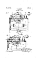
- Fig. l is a vertical section of a vacuum tank embodying this invention in the form having the atmosphere valve seated interiorly of the ifacuum chamber, so that the suction tends to unseat it.
- FIG. 2 is a similar view of a form having the atmosphere inlet valve seated exteriorly of the vacuum chamber so that the suction tends to hold it to its seat-
- the vacuum chamber is indicated by reference letter, A; the outer or reserve chamber by B; the cap which closes both chambers at the top and secures them together' is denoted by reference letter, C.
- rlhe fuel inletconnection is shown at D, mounted in the cap, B.
- the outlet tting is shown at E, and the out-let valve at e.
- the suction connection is shown at l41 mounted in the cap plate, C.
- the cap plate is formed eXteriorly with a depression, l0, for seating a cylindrical auX- iliary chamber, H, and in the bottom of the depression the cap plate has a slot, 40, with the left hand portion of which an aperture, ll, in the lower side of the cylindrical auxiliary chamber, H, is registered, said cham-l ber, H, being fitted to the depression, l0, in the cap and lodged therein with an interposed packing, 4S, for rendering the junction liquid tight when the auxiliary chamber is clamped in place by means of clamping straps, 43, i3'.
- Registered slots, l() and el serve to make the cavity of the auxiliary chamber a continuation of the cavity of the main vacuum ⁇ chamber so that the two elements, l and l-l, constitute together an enclosure in whicn partial vacuum may be produced by suction through the suction connectioiLF.
- the atmosphere inlet port is formed in one end ot the auxiliary cylindrical chamber, H, as seen at 20.
- the opposite end wall of this chamber is formed by a flexible diaphragm, 250, clamped1 at its peripheral margin on the inturned flange, 3l, of the cylindrical chamber.
- a rod., ilo which maybe referred to as the valve stein and also as the diaphragm stem, is secured at one end to the diaphragm, 30, at the center of the latter, and at the other end the rod carries the atmosphere valve, 50, adjustably secured on the threaded end oit the rod between binding nuts, 50a, the rod being furnished with a guide bearing at the center of a spider-formed cap, 20a, which constitutes the head of the chamber having the atmosphere inlet, 20, as mentioned.
- the other arm, 42, of the bell crank lever constitutes one member of a snap action which comprises a rod, 49, pivoted to a bracket, 5l, depending ⁇ from the cap plate, C, the free end of the red extending loosely through a small aperture, 53, in a laterally bent flange, 42, of the lever arm, a2, and a coil spring, 55, on the rod, 49, reacting between washers, 56 and 5T, loose on the rod affords snap action in the familiar manner not requiring further description.
- the lever arm, 42 has an extension, 58, from the lower end of the flange, 42"', from which there is pivotally suspended a rod, GO, for carrying Pleat, (il, slidingly between lower and upper stops, G2 and 63, respectively.
- the bell crank lever, 42 may desirably be formed with a counterbalancing arm, del,A as sho-wn. y
- a casing enclosing a chamber having connection with a source of suction for producing partialvacuum in the chamber, said chamber having a liquid inlet, a liquid outlet and an atmosphere inlet; a valve controlling the atmosphere inlet; a limited part 'of the enclosing wall exteriorly exposed to atmosphere being inwardly and outwardly movable without opening the wall; operating connections between said movable part of the wall and the atmosphere inlet valve arranged for opposing to each other respectively the actions due to vacuum in the chamber, said connections being dimensioncd 'and arranged for substantially balancing said actions against each other; means oilgierated by change of level of the liquid content of the chamber for operating said connections fior opening and closing the valve, and a snap action interposed between said liquid levelopei'ated means and said operating and balancing connections between the valve and the movable wall arranged to exert force in opposition to one of said counter-balanced actions by its snap caused by the high liquid level and in opposition to the
- a vacuum chainber having connection with a soui'ce ot suction for producing partial vacuum in the' posite ends respectively; a flexible diaphragmy .closing one of said apertures and exteriorly exposedto the atmosphere, a valve arranged to seat at and close the other aperture, means positively connecting said diaphragm and said valve arranged to hold Vthe valve seated at a normal position of the diaphragm from which it is adapted to be limitedly moved by lexure; a lever fulcrumed for extending through the registered apertures of communication between the two chambers operatively connected with said positively connecting means, means in the vacuum chamber adapted to be operated by change of level of the liquid content of said chamber, and operating connections between said level-operated means and said lever ⁇ for moving the connected diapliragmand valve in valve-opening direction at a predetermined position of said level-op-v erated means due to high level of theliquid content of the chamber, and for
- the level-operated means in the vacuum chamber and the lever connected for operating thediaphragmA and valve comprising a spring snap action arranged for adding the reaction of its spring to the atmosphericp'ressure for opening the valve at the upper limit of the change ofvlevel and to said pressure on-the diaphragm for closing the valve at the lower limit;
- a construction for the purpose indicated comprising a yvacuum chamber having suction connection, and fuel inlet and fuel outlet, an auxiliary chamber mounted upon the vacuumchamber, said chambers having registered ports Vof communication between them, the auxiliary chamber having two apertures,
Landscapes
- Engineering & Computer Science (AREA)
- Chemical & Material Sciences (AREA)
- Combustion & Propulsion (AREA)
- Mechanical Engineering (AREA)
- General Engineering & Computer Science (AREA)
- Fluid-Driven Valves (AREA)
Description
Dec. 9, 1930. Q s, BURTON v 1,784,130
VACUUM TANK Filed Feb. 21, 1929 Patented bec. 9, 1930 PATENT ol-"FICE CHARLESV S. BUR'I0N,T0F OAK PARK, ILLINOIS VACUUM TANK Application led February 21, 1929. Serial No. 341,586.
The purpose of this invention is to provide 'an improved construction in a vacuum tank adapted to facilitate dispensing with a valve to control the suction connection without creating the embarrassment which is liable to accompany the omission of the suction valve. It consists in the elements and features of construction shown and described as indicated in the claims.
It is well understood by those familiar with vacuum fuel feeding-devices, that when, for any reason7 in a vacuum tank the valvevu'sually provided for controlling thesuctionV port is omitted, it is necessary to limit the size of the suction port to a very small fraction of the atmosphere port and valve, in order that the opening of the atmosphere valve shall reduce the vacuum to a degree to permit 'the chamber of convenient depth to dischar e by gravity for asubstantial portion o the depth. And it is alsowell understood that the relatively large size of the atmosphere valve necessitates a correspondingly large ioat to have the buoyant value necessary for breaking theV suction hold onv the valve for opening it when the chamber is filledand should be discharged.
Dispensing with the valvek at the suction port thus creates the dilemmathat if the sucfilling of the vacuum chamber with` fuel, the atmosphere port must be so large thatthe float required to break the suction hold must be very large and the vacuum chamber correspondingly large withoutenlarged fuel capacity around the float, thusrendering the total construction large and correspondingly expensive and inconvenient for installation on engine or vehicle suction.
Onthe other hand, ifthe suction portis made small enough to permit the atmosphere port to be small enoughto require a valve small enough to be broken from the suction hold by a moderate size afloat, the fuel feeding capacity is rendered undesirably low.
This dilemma is avoidedin the present in- Y vention bythe expedient of getting the atmosphere valve, which is stressed to its. seat inwardly with respect to the vacuum chamber by the suction,vwith anotherv element also artion port is made large enough to ensurerapid ranged to be stressed inwardly by the saine suction, the connection between the two ele-v ments being arranged to oppose the two stressed to each other, so that they are substantially counter-balanced; and however large theatmosphere inlet port may be made, the counter-balancing element may be made of equal or nearly equal exposure to the suc-r tion, so that the valve will be held to its seat by only the amount of .pressure which is produced by the relative dimensions Vof thejparts for causing the valve to be thus held by the minimum force judged necessary to ensure thatit will not be jarred from its seat by the {lunning of the engine or the travel of the ve- 85 icle. l p V The character of this expedient adapts it to be employed either in a construction in which the atmosphere valve 'is seatedy interiorly,v 'so as to be held to its seat by the suction, 70 as inthe usual vacuum tank construction, or Y in a construction in whichI that valve is located exteriorly of thevacuum chamber and would be unseated by the suction; for the' counter-balancing element may be arranged in either case for experiencing the suction in the same direction as the valve, and may be connected for transmitting the stress in the reverse direction forcounter-balancing the stress Von the valve. 1
' In the construction illustrated, the counterbalancing element is a flexibleV diaphragm -mounted at an aperture in the chamber wall so asto constitute a movable part of that wall; and in one of the forms Vof construction by the. suction; and in the 'otherl form shown it is interior', adapted to beopened by the suction. Y
In either of these forms the areas of the valve and diaphragm may be effectively equal, separate means being employed to createoverbalance. of pressure' in favor of seat- -ingthe valve during the. filling period and like overbalance of pressure in favor ofopening the valve during thedischargingperiod. In the construction shown'in both forms the overbalance is furnished by the reaction of a spring sna' u action zwhich is brought into action in `t e manner ofsnapv actions com- '35 shown the valve-'is eXterior,-to be seated monly employed in the familiar type of vacuum tanks.
ln the drawings Fig. l is a vertical section of a vacuum tank embodying this invention in the form having the atmosphere valve seated interiorly of the ifacuum chamber, so that the suction tends to unseat it.
Figure 2 is a similar view of a form having the atmosphere inlet valve seated exteriorly of the vacuum chamber so that the suction tends to hold it to its seat- Referring to the drawings in both forms, the vacuum chamber is indicated by reference letter, A; the outer or reserve chamber by B; the cap which closes both chambers at the top and secures them together' is denoted by reference letter, C. rlhe fuel inletconnection is shown at D, mounted in the cap, B. The outlet tting is shown at E, and the out-let valve at e. The suction connection is shown at l41 mounted in the cap plate, C.
The cap plate is formed eXteriorly with a depression, l0, for seating a cylindrical auX- iliary chamber, H, and in the bottom of the depression the cap plate has a slot, 40, with the left hand portion of which an aperture, ll, in the lower side of the cylindrical auxiliary chamber, H, is registered, said cham-l ber, H, being fitted to the depression, l0, in the cap and lodged therein with an interposed packing, 4S, for rendering the junction liquid tight when the auxiliary chamber is clamped in place by means of clamping straps, 43, i3'. Registered slots, l() and el, serve to make the cavity of the auxiliary chamber a continuation of the cavity of the main vacuum` chamber so that the two elements, l and l-l, constitute together an enclosure in whicn partial vacuum may be produced by suction through the suction connectioiLF. f
The atmosphere inlet port is formed in one end ot the auxiliary cylindrical chamber, H, as seen at 20. The opposite end wall of this chamber is formed by a flexible diaphragm, 250, clamped1 at its peripheral margin on the inturned flange, 3l, of the cylindrical chamber. l
A rod., ilo, which maybe referred to as the valve stein and also as the diaphragm stem, is secured at one end to the diaphragm, 30, at the center of the latter, and at the other end the rod carries the atmosphere valve, 50, adjustably secured on the threaded end oit the rod between binding nuts, 50a, the rod being furnished with a guide bearing at the center of a spider-formed cap, 20a, which constitutes the head of the chamber having the atmosphere inlet, 20, as mentioned.
A bracket, il?, depending from the under side of the cap, C, striding'the slot, 40, supports the fulcrum, 48, of a bell crank lever, lL/l, one arm of which entends up through tl e registered slots, l0 ani 41, and at its upper end engages by means of a forked slot, lll, a pin, 45, projecting from the valve-and-diaphragm stem, 45. The other arm, 42, of the bell crank lever constitutes one member of a snap action which comprises a rod, 49, pivoted to a bracket, 5l, depending` from the cap plate, C, the free end of the red extending loosely through a small aperture, 53, in a laterally bent flange, 42, of the lever arm, a2, and a coil spring, 55, on the rod, 49, reacting between washers, 56 and 5T, loose on the rod affords snap action in the familiar manner not requiring further description. The lever arm, 42, has an extension, 58, from the lower end of the flange, 42"', from which there is pivotally suspended a rod, GO, for carrying Pleat, (il, slidingly between lower and upper stops, G2 and 63, respectively.
The operation of this construction will be understood from the foregoing description of the structure, but may b e further described as follows Starting with the tank empty and having the suction connection, F, connected with the source of connection as the intake manifold of the engine to be served, the atmosphere valve'being held closed by the weight of the float operating through the lever connections with the diaphragm an d valve stem, 45, liquid will be drawn in by suction anddelivered through the connect-ion, D, into the vacuum chamber, A, lifting the float, 6l, until it encounters the upper stops, 63, whereupon the rise of the float will be halted until the further rise of the liquid level causes the lioat to be suiiiciently immersed past its plane of balance as to buoyancy, until the buoyant value resulting from such immersion is sutlicient to overcome the resistance of the snap action spring; whereupon the bell crank lever will be rocked in the direction for opening the atmosphere valve. In this operation it .will be remembered that the partial vacuum developed in the chamber while the atmosphere valve is closed and the chamber is idlling with liquid, operates for suction to a substantially equal degree upon the diaphragm, 30, tending to hold the valve closed, and upon the valve itself, tending to open it, so that the valve is initially held seated by the reaction ofthe snap action spring; and since this snap action spring need only be stiff enoughto hold the parts safely against the liability of the valve being jarred open by the vibration of the engine or the olting ofthe vehicle, a very small iioat is sutiicient to operate the device in the manner described. T le atmosphere port being very large relative to the suction port, f, the vacuum in the chamber is substantially overcome by th opening of the atmosphere valve, and the liquid content is discharged by gravity, low* eringtl e float until it encounters the lower stop, 62, where it will be halted for a brief instant while. the continued lowering of the level causes the float to be inconipletely supported 'by the liquid to the extentthat its weight will overcome the resistance of the snap action spring which, reacting, reverses the movement, and seats the atmosphere inlet valve; whereupon the parts being in the initial position, the cycle of operation will be repeated. q
In order that the forces operating on the valve for moving it in either direction shally be balanced except as to the action of the snap action spring, and so 'that the reaction of that spring constitutes the only force to be overcome by the buoyant value of the float rising or the weight of the float descendingin order to operate. the valve, the bell crank lever, 42, may desirably be formed with a counterbalancing arm, del,A as sho-wn. y
The above description as to the parts applies to the construction shown in Figure 2 with the exception that the atmosphere valve is shown at the opposite end of the cylindrical auxiliary chamber, D, and is seated exteriorly 'of the chamber', the diaphragm being at the rightl hand end and mounted as in Figure l. fithout further description it Will beunderstood that the operation of the device is identical withthat of the construction shown inFigui-e 1, the pressures due to vacuum in the chamber acting upon the diaphragm and valve being balanced, the suction tendin'g to hold the valve seated instead of opening it, and acting on the diaphragm for opposing the seating instead of opposing the opening movement of Vthe valve. A
I claim:
l. In a construction for the purpose indicated, a casing enclosing a chamber having connection with a source of suction for producing partialvacuum in the chamber, said chamber having a liquid inlet, a liquid outlet and an atmosphere inlet; a valve controlling the atmosphere inlet; a limited part 'of the enclosing wall exteriorly exposed to atmosphere being inwardly and outwardly movable without opening the wall; operating connections between said movable part of the wall and the atmosphere inlet valve arranged for opposing to each other respectively the actions due to vacuum in the chamber, said connections being dimensioncd 'and arranged for substantially balancing said actions against each other; means oilgierated by change of level of the liquid content of the chamber for operating said connections fior opening and closing the valve, and a snap action interposed between said liquid levelopei'ated means and said operating and balancing connections between the valve and the movable wall arranged to exert force in opposition to one of said counter-balanced actions by its snap caused by the high liquid level and in opposition to the other of said counterbalanced actions by its snap caused by the low liquid level.
2. In a construction for the purpose indicated iii combination wth a vacuum chainber having connection with a soui'ce ot suction for producing partial vacuum in the' posite ends respectively; a flexible diaphragmy .closing one of said apertures and exteriorly exposedto the atmosphere, a valve arranged to seat at and close the other aperture, means positively connecting said diaphragm and said valve arranged to hold Vthe valve seated at a normal position of the diaphragm from which it is adapted to be limitedly moved by lexure; a lever fulcrumed for extending through the registered apertures of communication between the two chambers operatively connected with said positively connecting means, means in the vacuum chamber adapted to be operated by change of level of the liquid content of said chamber, and operating connections between said level-operated means and said lever `for moving the connected diapliragmand valve in valve-opening direction at a predetermined position of said level-op-v erated means due to high level of theliquid content of the chamber, and for mov-ing the valveand diaphragm in the direction for closing the valve at a predetermined lowlevel of said liquid content. Y
3'. In the construction defined iny claim 2,
the areas of the two apertures in the auxiliary i chamber which are closed respectively by the diaphragm -and the valve being effectively equal orexposure ofthe diaphragm and valvek respectively to opposed atmospheric pressure andsuction within and without said auxiliaryV chamber, the connection between.
the level-operated means in the vacuum chamber and the lever connected for operating thediaphragmA and valve, comprising a spring snap action arranged for adding the reaction of its spring to the atmosphericp'ressure for opening the valve at the upper limit of the change ofvlevel and to said pressure on-the diaphragm for closing the valve at the lower limit; n
4. A construction for the purpose indicated comprising a yvacuum chamber having suction connection, and fuel inlet and fuel outlet, an auxiliary chamber mounted upon the vacuumchamber, said chambers having registered ports Vof communication between them, the auxiliary chamber having two apertures,
ture at seating position'of the valve, positive connection between the diaphragm and the valve for simultaneous movement upon exure of the diaphragm due tok partial lli) va flexible diaphragn mounted on the chamber Y i l wall for closing one of said apertures,V a valve suitably mounted for closing theother aper-
Priority Applications (1)
| Application Number | Priority Date | Filing Date | Title |
|---|---|---|---|
| US341586A US1784130A (en) | 1929-02-21 | 1929-02-21 | Vacuum tank |
Applications Claiming Priority (1)
| Application Number | Priority Date | Filing Date | Title |
|---|---|---|---|
| US341586A US1784130A (en) | 1929-02-21 | 1929-02-21 | Vacuum tank |
Publications (1)
| Publication Number | Publication Date |
|---|---|
| US1784130A true US1784130A (en) | 1930-12-09 |
Family
ID=23338179
Family Applications (1)
| Application Number | Title | Priority Date | Filing Date |
|---|---|---|---|
| US341586A Expired - Lifetime US1784130A (en) | 1929-02-21 | 1929-02-21 | Vacuum tank |
Country Status (1)
| Country | Link |
|---|---|
| US (1) | US1784130A (en) |
-
1929
- 1929-02-21 US US341586A patent/US1784130A/en not_active Expired - Lifetime
Similar Documents
| Publication | Publication Date | Title |
|---|---|---|
| US2491521A (en) | Float valve for fuel systems | |
| US1784130A (en) | Vacuum tank | |
| US1933379A (en) | Charge forming device | |
| US3811464A (en) | Ballcock | |
| US1893473A (en) | Fuel pump | |
| US2888030A (en) | Liquid level responsive valve | |
| US1912203A (en) | Fuel system for internal combustion engines | |
| US1675270A (en) | Control device | |
| US1446902A (en) | Vacuum feeding device | |
| US2150714A (en) | Air eliminator | |
| US1268780A (en) | Vacuum feed device for elevating liquid. | |
| US1583461A (en) | Combined vacuum tank and liquid meter | |
| US2171620A (en) | Float valve device for use in metering liquids | |
| US1389907A (en) | Water-inlet valve for tanks | |
| US1799196A (en) | Vacuum tank | |
| US1784129A (en) | Vacuum tank | |
| US1372931A (en) | John j | |
| US1415195A (en) | Vacuum feeding apparatus | |
| US1385337A (en) | Fuel-feeding- system fob automobiles | |
| US1383273A (en) | Flushing apparatus | |
| US1799195A (en) | Vacuum tank | |
| US2211880A (en) | Inverted bucket steam trap | |
| US801161A (en) | Water-trap. | |
| US1293789A (en) | Valve mechanism for vacuum feed devices. | |
| US1556186A (en) | Liquid meter |