US1784119A - Oscillograph - Google Patents
Oscillograph Download PDFInfo
- Publication number
- US1784119A US1784119A US408390A US40839029A US1784119A US 1784119 A US1784119 A US 1784119A US 408390 A US408390 A US 408390A US 40839029 A US40839029 A US 40839029A US 1784119 A US1784119 A US 1784119A
- Authority
- US
- United States
- Prior art keywords
- oscillograph
- circuit
- grid
- cathode
- resistance
- Prior art date
- Legal status (The legal status is an assumption and is not a legal conclusion. Google has not performed a legal analysis and makes no representation as to the accuracy of the status listed.)
- Expired - Lifetime
Links
- 230000009466 transformation Effects 0.000 description 3
- 238000010276 construction Methods 0.000 description 1
- 238000010586 diagram Methods 0.000 description 1
- 230000005672 electromagnetic field Effects 0.000 description 1
- 238000009413 insulation Methods 0.000 description 1
- 238000005259 measurement Methods 0.000 description 1
- 238000012986 modification Methods 0.000 description 1
- 230000004048 modification Effects 0.000 description 1
- 230000001603 reducing effect Effects 0.000 description 1
- 230000003068 static effect Effects 0.000 description 1
- 238000000844 transformation Methods 0.000 description 1
- 230000001131 transforming effect Effects 0.000 description 1
Images
Classifications
-
- G—PHYSICS
- G01—MEASURING; TESTING
- G01R—MEASURING ELECTRIC VARIABLES; MEASURING MAGNETIC VARIABLES
- G01R13/00—Arrangements for displaying electric variables or waveforms
- G01R13/04—Arrangements for displaying electric variables or waveforms for producing permanent records
Definitions
- My invention relates broadly to an oscillograph apparatus and more particularly to a circuit arrangement for an oscillograph in which the oscillograph record may be taken 5 independently of the characteristics of the circuits of the oscillograph.
- One of the objects of my invention is to provide a circuit arrangement for an oscillograph in which voltage oscillograms may be made by employing a transformation circuit for impressing a smaller potential upon a low impedance circuit and developing current variations that can be registered by the oscillograph.
- Another object of my invention is to provide a circuit arrangement for an oscillograph in which an electron tube is employed in inverted order, with the input circuit included between'the plate and cathode and the output circuit included between the grid and cathode and connected to the oscillograph vibrator, whereby the voltage to be photographed may be applied directly to the input circuit and a reducing action obtained for transforming the impressed voltage into a smaller potential acting in the output circuit for developing current variations that can be registered by the oscillograph.
- Still another object of my invention is to provide a circuit arrangement for an oscillograph wherein oscillograms may be taken of relatively high voltage by the direct connection of an electron tube circuit to the potential to be photographed and the transformation thereof into a lower potential develop-' ing current variations which can be registered upon the oscillograph.
- a further object of my invention is to provide an oscillograph circuit which consumes substantially negligible power and which may be connected permanently in a power line for observing at all times the condition of the power distribution system by the making of a continuous oscillograph record of the power transmitted disturbances and other surges in the line for enabling eflicient operation of a power distribution'system to be maintained.
- Figure 1 diagrammatically illustrates circuit arrangements of the oscillograph of my cluded between the grid and cathode electrodes and constitutes a low impedance path.
- the input circuit across the plate and cathode electrodes may be connected directly to the high potential circuit in which the voltage characteristics are to be measured.
- the voltage which is impressed upon the input circuit is transformed into a smaller potential acting in the low impedance grid circuit for developing current variations that can be registered by the oscillogra )h.
- the oscillograph functions substantial y independently of the circuit characteristics of the inverted electron tube system as the inverted electron tube system consumes substantially no current.
- reference character 1 designates the electron tube employing thecircuit arrangement of my invention.
- the electron tube 1 includes cathode 2, grid 3 and plate 4,;
- the input circuit of the electron tube connects between cathode 2 and plate 4.
- a negative biasing potential is applied to the plate 4 from battery 5 through resistance 6.
- the input circuit connects through condenser 7 to the power circuit 8 on which the oscillogra h measurements are to be taken.
- I have deslgnated generally the elements of the power distribution system at 9 to which the oscillograph circuit of my invention may be permanently connected by reason of its ow power consuming characteristics.
- the cathode 2 is heated from a suitable source 10 through impedance-11.
- the output circuit extends between cathode 2 and grid 3 completing a low impedance path through resistance 12, resistance 14 and source of potential 15.
- the positive terminal of the source of potential 15 is directed toward the grid electrode 3.
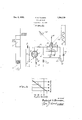
- the voltage of the plate biasing battery 5 is such as to cause the electron tube 1 to operate on a straight line portion of its characteristic curve, indicated in the diagram of Fig. 2.
- the resistance 12 is introduced in the output circuit for the purpose of straightening or correcting the characteristic of the tube and has a value which is at least twice the dynamic grid resistance.
- the vibrator element 16 of the oscillograph which is suspended at 18 and 19 for movement within an electromagnetic field designated at 17, is connected in a circuit across the terminals of resistance 14.
- the oscillograph circuit includes battery 20 and potentiometer 21, with a variable tap 22 thereon.
- the mirror of the vi-" brator is exposed to a source of-light 23, which is reflected and photographically recorded on moving film 24.
- the parts of the oscillograph have been shown in elementary form and are merely for the purpose of illustrating the principles of my invention and are not to be regarded as setting forth structural features of my invention.
- the resistance 14 and the potentiometer 2] balance the normal steady grid current out of the vibrator 16. Values of 100 to 1000 ohms are suitable for resistance 14, while potentiometer 21 should have considerably less resistance than resistance 14. I have found that a resistance proportion of 1 to 10 between the value of resistance 14 and the resistance of potentiometer 21 is satisfactory.
- the distortion introduced by the tube can be determined from the static curves, and
- the vibrator of an ordinary oscillograph requires from 50 to 100 milliamperes of current to give a good deflection. This amount of current generally requires two 7.5-watt tubes in parallel, or a single 50-watt tube, if distortion is to be avoided in the transforma tion.
- the plate circuit of the inverted vacuum tube can be safely introduced into any highvoltage low-amperage circuit.
- the high voltage to be photographed is stepped down without additional apparatus.
- the oscillo graph is ina low potential circuit, and can accordingly be handled easily and safely.
- the plate biasing battery can frequently be dispensed with.
- An electrical indicating system comprising, a source of variable current, an electron discharge device including plate, grid and cathode, an input circuit included between said plate and cathode and connected to said source of variable current, means interposed in said input circuit and adapted to render the alternating component only of said variable current effective on said plate, an output circuit included between said grid and cathode, and an electrical indicating device in said output circuit.
- An oscillograph system comprising, a source of variable current, an electron discharge device including a plate, grid and cathode, an input circuit included between said plate and cathode and connected to said source of variable current, means interposed in said input circuit and adapted to render the alternating component only of said variable current effective on said late, an output circuit included between sai grid and cathode, and an oscillograph vibrator connected 1n said output circuit.
- An electrical indicating system comprising, a source of fluctuating voltage, an electween said plate and cathode and capacitively coupled to said source offluctuatmg voltage, an output circuit included between said grid and said cathode, and an electrical inicating device connected in said output circuit.
- An oscillograph system comprising, a source of fluctuatin voltage, an electron discharge device inclu ing plate, grid and oath ode, an input circuit mcluded between said plate and cathode and capacitively coupled to said source of voltage, an output circuit included between said grid and filament, and an oscillograph vibrator connected in said output circuit, said vibrator being adapted to indicate the instantaneous value of said voltage.
- An oscillograph system comprising, a source of fluctuatin voltage, an electron discharge device inclu ing plate, grid and cathode, an input circuit mcluded between said plate and cathode, a capacitance interposed in said input circuit between said plate -and said source of voltage, an output circuit included between said grid and cathode, and an oscillograph vibrator connected in said output circuit, said vibrator being adapted to follow the fluctuations of said voltage.
Landscapes
- Physics & Mathematics (AREA)
- General Physics & Mathematics (AREA)
- Electron Sources, Ion Sources (AREA)
Description
Dec. 9, 1930. F. E. TERMAN 1,784,119
- OSCILLOGRAPH Filed Nov. 19, 1929 INVENTOR.
$440M wzmw,
Patented Dec. 9, 1930 UNITED STATES PATENT OFFICE i FREDERICK E. TIER-MAN, OF STANFORD UNIVERSITY, CALIFORNIA, ASSIGNOR TO WIRED RADIO, INC, 01 NEW YORK, N. Y., A CORPORATION OF DELAWARE OSCILLOGRAPH Application filed November 19, 1929.. Serial No. 408,390.
My invention relates broadly to an oscillograph apparatus and more particularly to a circuit arrangement for an oscillograph in which the oscillograph record may be taken 5 independently of the characteristics of the circuits of the oscillograph.
One of the objects of my invention is to provide a circuit arrangement for an oscillograph in which voltage oscillograms may be made by employing a transformation circuit for impressing a smaller potential upon a low impedance circuit and developing current variations that can be registered by the oscillograph.
Another object of my invention is to provide a circuit arrangement for an oscillograph in which an electron tube is employed in inverted order, with the input circuit included between'the plate and cathode and the output circuit included between the grid and cathode and connected to the oscillograph vibrator, whereby the voltage to be photographed may be applied directly to the input circuit and a reducing action obtained for transforming the impressed voltage into a smaller potential acting in the output circuit for developing current variations that can be registered by the oscillograph.
Still another object of my invention is to provide a circuit arrangement for an oscillograph wherein oscillograms may be taken of relatively high voltage by the direct connection of an electron tube circuit to the potential to be photographed and the transformation thereof into a lower potential develop-' ing current variations which can be registered upon the oscillograph.
A further object of my invention is to provide an oscillograph circuit which consumes substantially negligible power and which may be connected permanently in a power line for observing at all times the condition of the power distribution system by the making of a continuous oscillograph record of the power transmitted disturbances and other surges in the line for enabling eflicient operation of a power distribution'system to be maintained.
Other and further objects of my invention reside in the circuit arrangement for an oscillograph, as setforth more particularly in the specification hereinafter following and by reference to the accompanying drawings In which:
Figure 1 diagrammatically illustrates circuit arrangements of the oscillograph of my cluded between the grid and cathode electrodes and constitutes a low impedance path. The input circuit across the plate and cathode electrodes may be connected directly to the high potential circuit in which the voltage characteristics are to be measured. The voltage which is impressed upon the input circuit is transformed into a smaller potential acting in the low impedance grid circuit for developing current variations that can be registered by the oscillogra )h. The oscillograph functions substantial y independently of the circuit characteristics of the inverted electron tube system as the inverted electron tube system consumes substantially no current.
By reason of the low current consuming properties of the oscillograph system of my invention, it is practical to permanently connect the oscillograph to a power circuit in a power distribution system for observing a continuous record of the power transmitted and of the surges and disturbances which ocour in the line. The character of service rendered to customers may thereby be readily checked.
Referring to the drawings in more detail, reference character 1 designates the electron tube employing thecircuit arrangement of my invention. The electron tube 1 includes cathode 2, grid 3 and plate 4,; The input circuit of the electron tube connects between cathode 2 and plate 4. A negative biasing potential is applied to the plate 4 from battery 5 through resistance 6. The input circuit connects through condenser 7 to the power circuit 8 on which the oscillogra h measurements are to be taken. I have deslgnated generally the elements of the power distribution system at 9 to which the oscillograph circuit of my invention may be permanently connected by reason of its ow power consuming characteristics. The cathode 2 is heated from a suitable source 10 through impedance-11. The output circuit extends between cathode 2 and grid 3 completing a low impedance path through resistance 12, resistance 14 and source of potential 15. The positive terminal of the source of potential 15 is directed toward the grid electrode 3. The voltage of the plate biasing battery 5 is such as to cause the electron tube 1 to operate on a straight line portion of its characteristic curve, indicated in the diagram of Fig. 2.
The resistance 12 is introduced in the output circuit for the purpose of straightening or correcting the characteristic of the tube and has a value which is at least twice the dynamic grid resistance. The vibrator element 16 of the oscillograph which is suspended at 18 and 19 for movement within an electromagnetic field designated at 17, is connected in a circuit across the terminals of resistance 14. The oscillograph circuit includes battery 20 and potentiometer 21, with a variable tap 22 thereon. The mirror of the vi-" brator is exposed to a source of-light 23, which is reflected and photographically recorded on moving film 24. The parts of the oscillograph have been shown in elementary form and are merely for the purpose of illustrating the principles of my invention and are not to be regarded as setting forth structural features of my invention. The resistance 14 and the potentiometer 2] balance the normal steady grid current out of the vibrator 16. Values of 100 to 1000 ohms are suitable for resistance 14, while potentiometer 21 should have considerably less resistance than resistance 14. I have found that a resistance proportion of 1 to 10 between the value of resistance 14 and the resistance of potentiometer 21 is satisfactory.
The distortion introduced by the tube can be determined from the static curves, and
the oscillograms corrected accordingly. This distortion can be minimized by making use of the straight line portions of the characteristic, and also by inserting a resistance n series with the grid batter shown at 12 1n Fig. 1. This resistance as the efl'ect of straightening out the characteristlc, whlch becomes practically a straight line if 12 is two or three times the dynamic grid resistance. When the resistance is used a higher .grid battery otential must be employed to make up for t e additional voltage drop.
The vibrator of an ordinary oscillograph requires from 50 to 100 milliamperes of current to give a good deflection. This amount of current generally requires two 7.5-watt tubes in parallel, or a single 50-watt tube, if distortion is to be avoided in the transforma tion.
By reason of its practically infinite resistance, the plate circuit of the inverted vacuum tube can be safely introduced into any highvoltage low-amperage circuit. By the use of a tube with the proper step-down ratio, and with suitable insulation resistance, the high voltage to be photographed is stepped down without additional apparatus. The oscillo graph is ina low potential circuit, and can accordingly be handled easily and safely. In cases where it is desired to photograph a wave consisting of an alternating current potential superimposed on a D. C. potential, as in the case of the plate to filament voltage of an oscillating vacuum tube, the plate biasing battery can frequently be dispensed with.
I have found the oscillograph of my invention hi hly practical in its construction and success 111 in its operation. While I- have de scribed my invention in one of its preferred embodiments, I desire that it be understood that modifications may be made and that no limitations upon m invention are intended other than those w ich are imposed by the scope of the. appended claims.
What I claim as new and desire to secure by Letters Patent of the United States is as follows:
1. An electrical indicating system comprising, a source of variable current, an electron discharge device including plate, grid and cathode, an input circuit included between said plate and cathode and connected to said source of variable current, means interposed in said input circuit and adapted to render the alternating component only of said variable current effective on said plate, an output circuit included between said grid and cathode, and an electrical indicating device in said output circuit.
2. An oscillograph system comprising, a source of variable current, an electron discharge device including a plate, grid and cathode, an input circuit included between said plate and cathode and connected to said source of variable current, means interposed in said input circuit and adapted to render the alternating component only of said variable current effective on said late, an output circuit included between sai grid and cathode, and an oscillograph vibrator connected 1n said output circuit.
3. An electrical indicating system comprising, a source of fluctuating voltage, an electween said plate and cathode and capacitively coupled to said source offluctuatmg voltage, an output circuit included between said grid and said cathode, and an electrical inicating device connected in said output circuit.
4. An oscillograph system comprising, a source of fluctuatin voltage, an electron discharge device inclu ing plate, grid and oath ode, an input circuit mcluded between said plate and cathode and capacitively coupled to said source of voltage, an output circuit included between said grid and filament, and an oscillograph vibrator connected in said output circuit, said vibrator being adapted to indicate the instantaneous value of said voltage.
5. An oscillograph system comprising, a source of fluctuatin voltage, an electron discharge device inclu ing plate, grid and cathode, an input circuit mcluded between said plate and cathode, a capacitance interposed in said input circuit between said plate -and said source of voltage, an output circuit included between said grid and cathode, and an oscillograph vibrator connected in said output circuit, said vibrator being adapted to follow the fluctuations of said voltage.
In testimony whereof I aflix m signature.
FREDERICK E. T RMAN.
Priority Applications (1)
| Application Number | Priority Date | Filing Date | Title |
|---|---|---|---|
| US408390A US1784119A (en) | 1929-11-19 | 1929-11-19 | Oscillograph |
Applications Claiming Priority (1)
| Application Number | Priority Date | Filing Date | Title |
|---|---|---|---|
| US408390A US1784119A (en) | 1929-11-19 | 1929-11-19 | Oscillograph |
Publications (1)
| Publication Number | Publication Date |
|---|---|
| US1784119A true US1784119A (en) | 1930-12-09 |
Family
ID=23616098
Family Applications (1)
| Application Number | Title | Priority Date | Filing Date |
|---|---|---|---|
| US408390A Expired - Lifetime US1784119A (en) | 1929-11-19 | 1929-11-19 | Oscillograph |
Country Status (1)
| Country | Link |
|---|---|
| US (1) | US1784119A (en) |
Cited By (1)
| Publication number | Priority date | Publication date | Assignee | Title |
|---|---|---|---|---|
| US2764737A (en) * | 1952-06-13 | 1956-09-25 | Harry G Parke | Peak voltage meter |
-
1929
- 1929-11-19 US US408390A patent/US1784119A/en not_active Expired - Lifetime
Cited By (1)
| Publication number | Priority date | Publication date | Assignee | Title |
|---|---|---|---|---|
| US2764737A (en) * | 1952-06-13 | 1956-09-25 | Harry G Parke | Peak voltage meter |
Similar Documents
| Publication | Publication Date | Title |
|---|---|---|
| US2260933A (en) | Frequency meter | |
| US2250708A (en) | Time interval measuring means | |
| US2045800A (en) | Arc length indicator | |
| US2619552A (en) | Automatic drift corrector | |
| US2059004A (en) | Cathode ray oscillograph sweep circuit | |
| US2310328A (en) | Square wave generator | |
| US2119389A (en) | Frequency meter | |
| US2228367A (en) | Frequency meter | |
| US1611716A (en) | Measuring electrical quantities | |
| US2530619A (en) | Liquid level indicating means | |
| US2086965A (en) | Electrical measuring device | |
| US2032620A (en) | Electron discharge apparatus | |
| US2413020A (en) | Electronic relay | |
| US2231955A (en) | Phase shifting device | |
| US2412064A (en) | Saw-tooth wave generator | |
| US1784119A (en) | Oscillograph | |
| US2203468A (en) | Regulator for time delay circuits | |
| US1768262A (en) | Phase measuring system and method | |
| US2119194A (en) | Modulation meter | |
| US1889758A (en) | Means for transforming light impulses into current impulses | |
| US2162239A (en) | Electric indicating device | |
| US2522239A (en) | Visual alignment signal generator | |
| US2069934A (en) | Modulation meter | |
| US2102371A (en) | Impulse rate meter | |
| US2430699A (en) | Amplifier gain control |