US1781663A - Lamp socket - Google Patents
Lamp socket Download PDFInfo
- Publication number
- US1781663A US1781663A US23021A US2302125A US1781663A US 1781663 A US1781663 A US 1781663A US 23021 A US23021 A US 23021A US 2302125 A US2302125 A US 2302125A US 1781663 A US1781663 A US 1781663A
- Authority
- US
- United States
- Prior art keywords
- switch
- base
- face
- spring
- ratchet
- Prior art date
- Legal status (The legal status is an assumption and is not a legal conclusion. Google has not performed a legal analysis and makes no representation as to the accuracy of the status listed.)
- Expired - Lifetime
Links
Images
Classifications
-
- H—ELECTRICITY
- H01—ELECTRIC ELEMENTS
- H01R—ELECTRICALLY-CONDUCTIVE CONNECTIONS; STRUCTURAL ASSOCIATIONS OF A PLURALITY OF MUTUALLY-INSULATED ELECTRICAL CONNECTING ELEMENTS; COUPLING DEVICES; CURRENT COLLECTORS
- H01R33/00—Coupling devices specially adapted for supporting apparatus and having one part acting as a holder providing support and electrical connection via a counterpart which is structurally associated with the apparatus, e.g. lamp holders; Separate parts thereof
- H01R33/945—Holders with built-in electrical component
- H01R33/955—Holders with built-in electrical component with switch operated manually and independent of engagement or disengagement of coupling
- H01R33/9555—Holders with built-in electrical component with switch operated manually and independent of engagement or disengagement of coupling for screw type coupling devices
Definitions
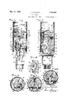
- My invention relates to electric lamp sockets, and particularly "to candle sockets.
- Figs. 2, 3, 4, and 6 are sections respectively on the lines 22, 3-3, 4-4, 5-5, 6-6, Fig. 7 is a side elevation of the insulating body with the metal parts removed; Fig. 8 is a side elevation at right angles to Fig. 1 showing certain detail modifications;
- Fig. 10 is a section corresponding to Fig.5
- Fig. 11 is an exploded view of certain of the details of the modification.
- Fig. 12 is a detail view of the eccentric supporting spindle, showing the eccentric in seci an insulating base block 15, flat on one side tmn.
- Thesocket shown in Figs. 1'(' comprises face. Recesses in this face form a switch chamber 16 and a separatechamber 17 for housing the switch actuating mechanism, the two-chambers being connected by a channel 18. *At one end of the block is mounted the screw shell 19 of the socket, the base flange of which is tit-riveted to a yoke 20 integral with a wire terminal strap 21. The latter liesagainst a flat face 22 at one side of the block -and carries adjacent its opposite end a I binding terminal 23.
- a switch bar 35 in the form of a Y-shaped yoke struck from sheet metal, is supported within the switch chamber on one end of a coil spring36 arranged in the well 37 opening to the switch chamber, and oscillates across the switch chamber from the position shown in F ig. 1, inwhich it bridges the-contacts 27 and 31, to the opposite side of the switch chamber, where it is halted by the wall 38 thereof in open circuit position.
- the circuit is thus made or broken on the center con- .the chamber.
- a cam plate 39 formed from sheet metal and-guided for rectilinear movement in the channel 18.
- the peak cam 40 of the plate slides in the crotch of the switch bar 35 which, under the action of its spring 36, is caused to ride down one or the other of the inclines a or b ofthe cam 40 as the peak of the latter passes the plane'of the switch bar.
- eccentric 41 is formed of insulating material
- ratchet disk 48 (Fig. 6), the ratchet teeth 49 of which engage opposite faces of the spindle web 45 to rotate the latter.
- the periphery of the ratchet disk is shaped to form a chain rail 50, the marginal lug 51 on which engages one end of the pull chain 52.
- a coil spring 53 against the face of the ratchet opposed to the teeth 49, bears a coil spring 53, one end of which enters a hole 54 in the ratchet disk for anchorage, while the opposite end of the spring is offset and received in a seat 55 formed in the fiat face of the block 15.
- the coil s ring 53 is coned and the ratchet disk simi arly shaped to receive the reduced end of the spring in order to render the mechanism more compact.
- the spring serves not only as a return spring for the chain rail and ratchet, but also as a compression spring which tends constantly to keep the ratchet in engagement with the edge of the spindle web 45 and in position to engage the latter when the disk is rotated.
- the chain 52 runs in a groove 58 in. the plate face of the base and may be provided with an enlarged ball X to prevent excess chain from entering the chamber17 on the sudden return movement of the chain rail, after actuation.
- the screw 62' passes in opposite direction through the block 15 and takes into a tapped hole in the terminal strap 32, which'overlies the cover plate 59.
- the screw bolt 63 passes through the cover plate and a transverse hole 66 adjacent the lower end of the block 15 and serves not only .t o hold the cover plate in position at its lower end, but also to constitute, with its tongue nut 67, means for establishing detachable connection with the slotted ends 68 of the legs 69 of the support ing hickey.
- the tongue 670 of the nut 67 enters a notch 671 at the lower end of the base 15 and is thus held against rotation as the screw 63 is turned up.
- the cover plate is apertured at 71 to permit the cam 41 and chain rail 50 to play therethrough, and at 72 to permit the switch contact 31 to pass therethrough from the wire terminal strap 32 into the switch chamber 16.
- the cover plate is extended as a lug 73 which projects into the space 74 between the screw shell and the boss 24 to effectively isolate the shank of center contact from the base flange of the screw shell 19.
- the cover plate has the further function as a limiting stop for the oscillating chain rail. Again it supports the cylindrical casing 75 which surrounds the screw shell 19 and the insulating body of the socket.
- the opposite margins of the lower end of the cover plate are provided with lateral extensions 76 which reach beyond the circumference of the casing 75, so that when the latter is pushed down upon the socket it abuts and is halted by its engagement with the shoulders 76 of the cover plate.
- cylindrical casing 75 is of paper, and may be deformed during handling, I provide means for keeping distended the portion thereof which surrounds the flat face of the block, particularly in the area of the switch operating mechanism.
- a lug 77 is formed on the side of the contact arm 32 (Figs. 4 and 5) and angled outward as shown to support the inner face of the casing 75. Interference with the operation of the chain rail is thus prevented.
- the switch spring 78 is of double cone construction, one end nesting in the depressed face of the ratchet disk 48, while the opposite end bears against the side face of the chamber 17.
- the added length of spring not only increases its strength but serves to maintain the ratchet disk more firmly pressed against the cooperating shoulders of the web 45 of the spindle 42.
- the long end 79 of the spring, by which it is tensioned is engaged'not in the seat 55, as in Fig. 1, but in an aperture 80 adjacent one margin of a guard plate 81.
- This guard plate eliminates the necessity for the lug 7 7 (Fig. 5) and takes the place of the latter as a lateral support for the casing tube 75.
- the guard plate 81 is preferably formed from thin spring metal and is provided at its opposite ends with lugs. 82 and 83 adapted to take into appropriate notches or apertures 84 and 85 in the fiber cover plate 59; To tension the spring 78 it is necessary merely to lift its end 79 from a position adjacent the base 15 in the area of the seat 55, insert the end through the hole 80 in the guard, the lug 83 of which has been previously inserted in the hole 85" in the cover plate 59, and then secure the guard plate in position by swinging it on the lug 83 as a pivot until lug 82 is in position to enter the notch 84, the guard plate being slightly sprung so that the lug 82will enter the notch automatically -upon release of the spring plate.
- the guard now overlies the combined chain rail and ratchet plate and supports the tube 75 when the latter is slipped over the socket. In order to accommodate the tube, one margin of the plate'is cutaway at'86 to conform substantially to the curvature of the tube wall.
- the camplate Upon the succeeding operation of the ratchet, the camplate is shifted by the eccentric in opposite direction, and the switch bar thrown across the switch chamberagain to close the circuit between'the switch contacts. In closed circuit position there is no danger'that current'will reach the pull chain 52 inasmuch as the eccentric 42 is of insulating material and spaces the cam bar from the cam spindle 42, web 45, etc.
- the socket is simple to manufacture by reason of the fact that practically all of themetal parts may be blanked and formed up from sheet material, no separate forming operation being necessary for many of the parts. No long through bolts are necessary to hold the screw shell or center contact in place.
- the insulating body is readily molded, and the assembly operation quickly and easily performed.
- the detachable hickey 69 renders installation easy, while the operation of the switch affords a wide double break of the circuit, without danger of arcing.
- An electric switch for a lamp socket or the like comprising a spring actuated oscillating switch bar, a reciprocating peakcam 'for controlling the throw of said bar, an
- An electric switch for a lamp socket or the like comprising a base recessed to afford a switch chamber, an operatin chamber and a connecting channel, in com ination with an oscillating switch bar in the switch cham: her, a reciprocating member controlling the throw of the switch bar and working in said channel, and ratchet means arranged in the operating chamber forf'actuating said reciprocating member.
- an insulating base laterally recessed to afford a switch chamber, a socket screw shell and center contact arranged at an end of the base, said center contact having a shank lying against that face of the base which isrecessed and a switch contact offset from the end of said shank and entering the switch chamber affordedby said lateral recess, in combination with an insulating cover plate facing the side of the base and holding said center contact in position thereweb of the disk being coned, in combination with a coned ratchet spring the small end of which enters the coned face of the ratchet disk. 5.
- a ratchet In an electric switch for lamp sockets or the like, a ratchet,a spindle on which said ratchet is freely journaled, and a web lying V substantially in the plane of and integral with the spindle engaged for rotation by the teeth of'the ratchet.
- a sheet metal spindle having a diameteral web, integral therewith, an eccentric on the spindle, and a rivet lug integral with the 'web and engaging said eccentric to cause its rotation with the spindle.
- an insulating base having a face recessed to form a switch 3 chamber, an independent operating chamber, open bearings on opposite ends of the operating chamber, in combination with a spring stressed switch bar freely arranged in the switch chamber, a sliding member freely extending between the switch and operating overlying therecessed side of the body, and
- an insulating base laterally recessed to form a switch chamber
- a screw shell mounted on the end of the base and having a base flange projecting beyond the laterally recessed face of the base
- a center contact located at the end of the base within the screw shell area and having a shank lying against the side face of the base and offset into the switch chamber to form a switch contact
- a cover plate of insulating material holding said center contact against the side face of the base and projecting between the center contact shank and the base flange of the screw shell to insulate the latter from each other.
- an insulating base having at one end a transverse channel, a cover plate against one side face of the base, av screw bolt piercing said cover plate and base, and a supporting hickey having notched-arms adapted to be detachably engaged at the opposite ends of said bolt.
- an oscillating switch bar In an electric switch mechanism, an oscillating switch bar, a reciprocating cam plate engaging the same, and an eccentric of insulating material engaging said plate to actuate it.
- aninsulating block flat on one side, socket contacts mounted at one end of the block, a switch mechanism projecting from the flat side face of the block, a tubular casing enclosing the socket contacts and block, and means maintaining the casing spaced from the fiat face of the block to insure non-interference with the switch mechanism.
- an insulating base having socket contacts at one end and switch mechanism projecting from one side of the base, a flat insulating plate overlying said side face and apertured to accommodate said mechanism, an enclosing tubular casing, and guard means carried by the flat plate for preventing depression of the tubular casing in the region of the projecting switch mechanism.
- an insulating base having socket contacts at one end and switch mechanism projecting from one side of the base, a flat insulating late overlying said side face and apertu to accom-
Landscapes
- Push-Button Switches (AREA)
Description
J. R. GARLSON Nov. 11, 1930.
My invention ,relates to electric lamp sockets, and particularly "to candle sockets.
in which my invention is embodied in one form;
Figs. 2, 3, 4, and 6 are sections respectively on the lines 22, 3-3, 4-4, 5-5, 6-6, Fig. 7 is a side elevation of the insulating body with the metal parts removed; Fig. 8 is a side elevation at right angles to Fig. 1 showing certain detail modifications;
9 is a section at right angles toFig. 8; Fig. 10 is a section corresponding to Fig.5
but illustrating the modified construction shown in Figs. 8 and 9; and Fig. 11 is an exploded view of certain of the details of the modification.
Fig. 12 is a detail view of the eccentric supporting spindle, showing the eccentric in seci an insulating base block 15, flat on one side tmn.
While I have shown my invention embodied in a candle socket to which it is particularly applicable, certain features of the construction' are of value insockets of other types. It will also be understood that various modifications in details of construction can readily be made which embody the invention.
Thesocket shown in Figs. 1'(' comprises face. Recesses in this face form a switch chamber 16 and a separatechamber 17 for housing the switch actuating mechanism, the two-chambers being connected by a channel 18. *At one end of the block is mounted the screw shell 19 of the socket, the base flange of which is tit-riveted to a yoke 20 integral with a wire terminal strap 21. The latter liesagainst a flat face 22 at one side of the block -and carries adjacent its opposite end a I binding terminal 23. Overlymg the end boss 24, which is embraced by the screw shell base flange and strap yoke 20, is a center contact 25 the shank 26 of which lies in a depression in the flat face of the block 15 and is offset at its opposite end to form a switch contact 27 which enters the switch chamber 16 and is supported against a wall 28 thereof, but to one side of the channel 18. Side lugs 29 on the shank enter recesses 30 in the base and hold the center contact against displacement.
A second switch contact 31 arranged within the switch chamber against the same wall 28 thereof, but on. the opposite side of the channel 18, is formed by the offset end of the strap 32, provided at its opposite end with an offset which enters the bay 33 and carries the binding terminal 34.
A switch bar 35, in the form of a Y-shaped yoke struck from sheet metal, is supported within the switch chamber on one end of a coil spring36 arranged in the well 37 opening to the switch chamber, and oscillates across the switch chamber from the position shown in F ig. 1, inwhich it bridges the- contacts 27 and 31, to the opposite side of the switch chamber, where it is halted by the wall 38 thereof in open circuit position. The circuit is thus made or broken on the center con- .the chamber.
To effect the oscillation of the switch bar I provide a cam plate 39 formed from sheet metal and-guided for rectilinear movement in the channel 18. The peak cam 40 of the plate slides in the crotch of the switch bar 35 which, under the action of its spring 36, is caused to ride down one or the other of the inclines a or b ofthe cam 40 as the peak of the latter passes the plane'of the switch bar.
To reciprocate the cam plate 39 I provide an eccentric 41 mounted on a spindle 42 and working in a gap 43 in the 'cam plate. The
eccentric 41 is formed of insulating material,
the chamber 17 To rotate the spindle I provide a ratchet disk 48 (Fig. 6), the ratchet teeth 49 of which engage opposite faces of the spindle web 45 to rotate the latter. The periphery of the ratchet disk is shaped to form a chain rail 50, the marginal lug 51 on which engages one end of the pull chain 52. Against the face of the ratchet opposed to the teeth 49, bears a coil spring 53, one end of which enters a hole 54 in the ratchet disk for anchorage, while the opposite end of the spring is offset and received in a seat 55 formed in the fiat face of the block 15. Preferably the coil s ring 53 is coned and the ratchet disk simi arly shaped to receive the reduced end of the spring in order to render the mechanism more compact. The spring serves not only as a return spring for the chain rail and ratchet, but also as a compression spring which tends constantly to keep the ratchet in engagement with the edge of the spindle web 45 and in position to engage the latter when the disk is rotated. A stop lug 56 on the chain rail engaging the under face of the cover plate, hereinafter described, limits the extent of rotation of the ratchet, while a second lug 57 engages the outer face of the cover plate (see Figs. 2 and 6) to limit the return of the parts under the. action of the spring 53. The chain 52 runs in a groove 58 in. the plate face of the base and may be provided with an enlarged ball X to prevent excess chain from entering the chamber17 on the sudden return movement of the chain rail, after actuation.
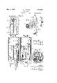
Overlying the fiat face of the block 15 is a cover plate 59 of insulating material, such as fiber. It is secured in position by screw bolts 60, 61, 62 and 63. Of these, the screw bolts 60 and 61 pass through the cover plate and take respectively into tapped lugs 64 and 65, the lug 64 being offset from the terminal strap 21, and the lug 65 being offset from or riveted to the yoke 20 integral with the strap 21. Both lugs 64-65, are seated against the opposite side of the block from the plate 59, so that the screw bolts anchor the screw shell 19 and strap 21, as Well as the cover plate, firmly in position. The screw 62' passes in opposite direction through the block 15 and takes into a tapped hole in the terminal strap 32, which'overlies the cover plate 59. The screw bolt 63 passes through the cover plate and a transverse hole 66 adjacent the lower end of the block 15 and serves not only .t o hold the cover plate in position at its lower end, but also to constitute, with its tongue nut 67, means for establishing detachable connection with the slotted ends 68 of the legs 69 of the support ing hickey. The tongue 670 of the nut 67 enters a notch 671 at the lower end of the base 15 and is thus held against rotation as the screw 63 is turned up. Mar inal lugs 690 spaced rpm the slotted ends of the lugs 68 of the hickey and offset inward, form stops against which the lower end of the base rests and by which the base is held from rocking on the bolt 63. The hickey nipple '70 screws as usual upon the threaded end of 39 reciprocates and constitutes the bearing against which the plate slides, and against which it is thrust by the switch bar spring 36. Since the cam plate constantly engages the switch bar 35, the latter and its spring 36 are held in the switch chamber 16 by the cover plate. The latter also overlies the notches. 46, 47 in the flat face of the block 15, and thus forms a bearing cap for the opposite ends of the spindle 42. Similarly it closes the channel 58 through which the chain emerges from the chamber 17, and thus retains the chain in proper position. The cover plate is apertured at 71 to permit the cam 41 and chain rail 50 to play therethrough, and at 72 to permit the switch contact 31 to pass therethrough from the wire terminal strap 32 into the switch chamber 16. Atone end the cover plate is extended as a lug 73 which projects into the space 74 between the screw shell and the boss 24 to effectively isolate the shank of center contact from the base flange of the screw shell 19. The cover plate has the further function as a limiting stop for the oscillating chain rail. Again it supports the cylindrical casing 75 which surrounds the screw shell 19 and the insulating body of the socket. Forthis purpose the opposite margins of the lower end of the cover plate are provided with lateral extensions 76 which reach beyond the circumference of the casing 75, so that when the latter is pushed down upon the socket it abuts and is halted by its engagement with the shoulders 76 of the cover plate.
Inasmuch as the cylindrical casing 75 is of paper, and may be deformed during handling, I provide means for keeping distended the portion thereof which surrounds the flat face of the block, particularly in the area of the switch operating mechanism. For this purpose a lug 77 is formed on the side of the contact arm 32 (Figs. 4 and 5) and angled outward as shown to support the inner face of the casing 75. Interference with the operation of the chain rail is thus prevented.
In Figs. 8 to 11, certain modifications are shown. As will be noted, the switch spring 78 is of double cone construction, one end nesting in the depressed face of the ratchet disk 48, while the opposite end bears against the side face of the chamber 17. The added length of spring not only increases its strength but serves to maintain the ratchet disk more firmly pressed against the cooperating shoulders of the web 45 of the spindle 42. The long end 79 of the spring, by which it is tensioned is engaged'not in the seat 55, as in Fig. 1, but in an aperture 80 adjacent one margin of a guard plate 81. This guard plate eliminates the necessity for the lug 7 7 (Fig. 5) and takes the place of the latter as a lateral support for the casing tube 75. The guard plate 81 is preferably formed from thin spring metal and is provided at its opposite ends with lugs. 82 and 83 adapted to take into appropriate notches or apertures 84 and 85 in the fiber cover plate 59; To tension the spring 78 it is necessary merely to lift its end 79 from a position adjacent the base 15 in the area of the seat 55, insert the end through the hole 80 in the guard, the lug 83 of which has been previously inserted in the hole 85" in the cover plate 59, and then secure the guard plate in position by swinging it on the lug 83 as a pivot until lug 82 is in position to enter the notch 84, the guard plate being slightly sprung so that the lug 82will enter the notch automatically -upon release of the spring plate. The guard now overlies the combined chain rail and ratchet plate and supports the tube 75 when the latter is slipped over the socket. In order to accommodate the tube, one margin of the plate'is cutaway at'86 to conform substantially to the curvature of the tube wall.
The operation of the .switch is readily understood. When the chain 52 is pulled out, thus rotating the ratchet 48, the spindle 42 is driven through the engagement of the ratchet teeth with the spindle web 45. As the spindle rotates, the eccentric 41 is carried around with it, and longitudinally displaces the cam plate 39. As the cam '40 passes the switch bar 35, the latter is displaced by the incline a, compressing the spring 36 until the peak of the cam passes the plane of the switch bar, whereupon the thrust of the spring 36' forces the bar to travel down the opposite incline b of the cam and causes the throw of the bar across the switch chamber 16 to open circuit position against the wall 38. Upon the succeeding operation of the ratchet, the camplate is shifted by the eccentric in opposite direction, and the switch bar thrown across the switch chamberagain to close the circuit between'the switch contacts. In closed circuit position there is no danger'that current'will reach the pull chain 52 inasmuch as the eccentric 42 is of insulating material and spaces the cam bar from the cam spindle 42, web 45, etc.
The socket is simple to manufacture by reason of the fact that practically all of themetal parts may be blanked and formed up from sheet material, no separate forming operation being necessary for many of the parts. No long through bolts are necessary to hold the screw shell or center contact in place. The insulating body is readily molded, and the assembly operation quickly and easily performed. The detachable hickey 69 renders installation easy, while the operation of the switch affords a wide double break of the circuit, without danger of arcing.
I claim- 1. An electric switch for a lamp socket or the like, comprising a spring actuated oscillating switch bar, a reciprocating peakcam 'for controlling the throw of said bar, an
eccentric for imparting mot-ion to said cam,
and a ratchet mechanism for rotating the eccentric.
2. An electric switch for a lamp socket or the like, comprising a base recessed to afford a switch chamber, an operatin chamber and a connecting channel, in com ination with an oscillating switch bar in the switch cham: her, a reciprocating member controlling the throw of the switch bar and working in said channel, and ratchet means arranged in the operating chamber forf'actuating said reciprocating member.
3. In an electric lamp socket, an insulating base laterally recessed to afford a switch chamber, a socket screw shell and center contact arranged at an end of the base, said center contact having a shank lying against that face of the base which isrecessed and a switch contact offset from the end of said shank and entering the switch chamber affordedby said lateral recess, in combination with an insulating cover plate facing the side of the base and holding said center contact in position thereweb of the disk being coned, in combination with a coned ratchet spring the small end of which enters the coned face of the ratchet disk. 5. In an electric switch for lamp sockets or the like, a ratchet,a spindle on which said ratchet is freely journaled, and a web lying V substantially in the plane of and integral with the spindle engaged for rotation by the teeth of'the ratchet.
6. In an electric switch, a sheet metal spindle having a diameteral web, integral therewith, an eccentric on the spindle, and a rivet lug integral with the 'web and engaging said eccentric to cause its rotation with the spindle. I
7 In an electric switch, an insulating base having a face recessed to form a switch 3 chamber, an independent operating chamber, open bearings on opposite ends of the operating chamber, in combination with a spring stressed switch bar freely arranged in the switch chamber, a sliding member freely extending between the switch and operating overlying therecessed side of the body, and
shouldered atone end, together with an insulating tube surrounding said screw shell and base, and abutting at one end against the shoulder of the cover plate.
9. In an electric lamp socket, an insulating base laterally recessed to form a switch chamber, a screw shell mounted on the end of the base and having a base flange projecting beyond the laterally recessed face of the base, a center contact located at the end of the base within the screw shell area and having a shank lying against the side face of the base and offset into the switch chamber to form a switch contact, together with a cover plate of insulating material holding said center contact against the side face of the base and projecting between the center contact shank and the base flange of the screw shell to insulate the latter from each other.
10. In an electric lamp socket, an insulating base having at one end a transverse channel, a cover plate against one side face of the base, av screw bolt piercing said cover plate and base, and a supporting hickey having notched-arms adapted to be detachably engaged at the opposite ends of said bolt.
11. In an electric switch mechanism, an oscillating switch bar, a reciprocating cam plate engaging the same, and an eccentric of insulating material engaging said plate to actuate it.
12. In a candle socket, aninsulating block flat on one side, socket contacts mounted at one end of the block, a switch mechanism projecting from the flat side face of the block, a tubular casing enclosing the socket contacts and block, and means maintaining the casing spaced from the fiat face of the block to insure non-interference with the switch mechanism.
13. In an electric lamp socket, an insulating base having socket contacts at one end and switch mechanism projecting from one side of the base, a flat insulating plate overlying said side face and apertured to accommodate said mechanism, an enclosing tubular casing, and guard means carried by the flat plate for preventing depression of the tubular casing in the region of the projecting switch mechanism.
modate said mechanism, an enclosing tubular casing, and guard means carried by the flat plate for preventing de ression of the tubular casing in the region 0 the projecting switch mechanism, said mechanism comprising a spring, one end of which 'is anchored to said guard means.
15. The combination with the construction specified in claim 3, of a lug on the shank of the center contact, the base being recessed to receive said lug, and said insulating cover plate also holding said lug in said recess.
In testimony whereof I have signed my name to this specification.
J OHANNES R. CARLSON.
14. In an electric lamp socket, an insulating base having socket contacts at one end and switch mechanism projecting from one side of the base, a flat insulating late overlying said side face and apertu to accom-
Priority Applications (1)
| Application Number | Priority Date | Filing Date | Title |
|---|---|---|---|
| US23021A US1781663A (en) | 1925-04-14 | 1925-04-14 | Lamp socket |
Applications Claiming Priority (1)
| Application Number | Priority Date | Filing Date | Title |
|---|---|---|---|
| US23021A US1781663A (en) | 1925-04-14 | 1925-04-14 | Lamp socket |
Publications (1)
| Publication Number | Publication Date |
|---|---|
| US1781663A true US1781663A (en) | 1930-11-11 |
Family
ID=21812669
Family Applications (1)
| Application Number | Title | Priority Date | Filing Date |
|---|---|---|---|
| US23021A Expired - Lifetime US1781663A (en) | 1925-04-14 | 1925-04-14 | Lamp socket |
Country Status (1)
| Country | Link |
|---|---|
| US (1) | US1781663A (en) |
-
1925
- 1925-04-14 US US23021A patent/US1781663A/en not_active Expired - Lifetime
Similar Documents
| Publication | Publication Date | Title |
|---|---|---|
| US2295484A (en) | Push-push operating mechanism for electric switches | |
| US1781663A (en) | Lamp socket | |
| US2271910A (en) | Switch | |
| US1971212A (en) | Electric snap switch | |
| US2212382A (en) | Socket for electric lamps | |
| US2389075A (en) | Switch | |
| US2802077A (en) | Miniature slide handle snap switch | |
| US2054502A (en) | Pull chain and wall switch | |
| US2124337A (en) | Switch | |
| US3143605A (en) | Combination push-push and momentary switch | |
| US1628415A (en) | Electric key socket | |
| US2867700A (en) | Switch | |
| US2769871A (en) | Electric switch and socket | |
| US2240200A (en) | Lamp holder | |
| US1695939A (en) | Dash switch | |
| US2230187A (en) | Electric snap switch | |
| US1669240A (en) | Electric switch | |
| US2128731A (en) | Electrical switch | |
| US1511440A (en) | Lever switch for electric sockets | |
| US1319963A (en) | Harry j | |
| US1394976A (en) | Electric switch | |
| US2102465A (en) | Lamp socket | |
| US1941721A (en) | Pull socket | |
| US1354803A (en) | Electric switch | |
| US1608118A (en) | Socket switch |