US1761896A - Power brake - Google Patents
Power brake Download PDFInfo
- Publication number
- US1761896A US1761896A US54194A US5419425A US1761896A US 1761896 A US1761896 A US 1761896A US 54194 A US54194 A US 54194A US 5419425 A US5419425 A US 5419425A US 1761896 A US1761896 A US 1761896A
- Authority
- US
- United States
- Prior art keywords
- drum
- collars
- brake
- shaft
- collar
- Prior art date
- Legal status (The legal status is an assumption and is not a legal conclusion. Google has not performed a legal analysis and makes no representation as to the accuracy of the status listed.)
- Expired - Lifetime
Links
- 230000033001 locomotion Effects 0.000 description 15
- 230000005540 biological transmission Effects 0.000 description 7
- 239000000835 fiber Substances 0.000 description 3
- 238000010276 construction Methods 0.000 description 2
- 230000000694 effects Effects 0.000 description 2
- 230000002093 peripheral effect Effects 0.000 description 2
- 101100328884 Caenorhabditis elegans sqt-3 gene Proteins 0.000 description 1
- 102100027069 Odontogenic ameloblast-associated protein Human genes 0.000 description 1
- 101710091533 Odontogenic ameloblast-associated protein Proteins 0.000 description 1
- 230000006835 compression Effects 0.000 description 1
- 238000007906 compression Methods 0.000 description 1
- 230000000994 depressogenic effect Effects 0.000 description 1
- 230000007717 exclusion Effects 0.000 description 1
- 238000009434 installation Methods 0.000 description 1
- 230000001788 irregular Effects 0.000 description 1
- 238000000034 method Methods 0.000 description 1
- 229920000136 polysorbate Polymers 0.000 description 1
- 238000007665 sagging Methods 0.000 description 1
- 230000013707 sensory perception of sound Effects 0.000 description 1
- 238000000926 separation method Methods 0.000 description 1
- 239000003351 stiffener Substances 0.000 description 1
- 238000004804 winding Methods 0.000 description 1
Images


Classifications
-
- B—PERFORMING OPERATIONS; TRANSPORTING
- B60—VEHICLES IN GENERAL
- B60T—VEHICLE BRAKE CONTROL SYSTEMS OR PARTS THEREOF; BRAKE CONTROL SYSTEMS OR PARTS THEREOF, IN GENERAL; ARRANGEMENT OF BRAKING ELEMENTS ON VEHICLES IN GENERAL; PORTABLE DEVICES FOR PREVENTING UNWANTED MOVEMENT OF VEHICLES; VEHICLE MODIFICATIONS TO FACILITATE COOLING OF BRAKES
- B60T13/00—Transmitting braking action from initiating means to ultimate brake actuator with power assistance or drive; Brake systems incorporating such transmitting means, e.g. air-pressure brake systems
- B60T13/02—Transmitting braking action from initiating means to ultimate brake actuator with power assistance or drive; Brake systems incorporating such transmitting means, e.g. air-pressure brake systems with mechanical assistance or drive
- B60T13/06—Transmitting braking action from initiating means to ultimate brake actuator with power assistance or drive; Brake systems incorporating such transmitting means, e.g. air-pressure brake systems with mechanical assistance or drive by inertia, e.g. flywheel
- B60T13/065—Transmitting braking action from initiating means to ultimate brake actuator with power assistance or drive; Brake systems incorporating such transmitting means, e.g. air-pressure brake systems with mechanical assistance or drive by inertia, e.g. flywheel of the propulsion system
Definitions
- This invention relates to improvements in power brakes forveh1cles,'and more particularly to-the mechanism for. actuating the same.
- a power brake actuating mechanism is pro video. which consists of a drum mounted upon a shaft connected positively with a ground wheel of the vehicle, so that as long as the vehicle is moving, the shaft is rotating, and the drum may be engaged for actuation of the brake. It is preferred to pro vide such a drum upon the transmission jshaftof'an automotive vehicle, at an appropriate point, so that the drum may be coupled for rotation by the'shaft by depression of the customary brake pedal ofthe vehicle. Further, compensating means are 7 provided between the shaft and the connective cables or rods, so that the actuating effort upon the. brakes proper may be equalized.
- a further feature of the invention is the provision of a transmission brake mechanism in connection with the aforesaid wheel brake mechanism.
- the structure is alsoprovided with a safety -means by which no seizing or binding is possible in the engagement of the several drums for actuation by the shaft.
- Another feature' is' the provision of spacing and bear ing means to prevent frictional dragging of of Fig. 2.
- means are pro the drum upon the shaft during normal propulsion of the vehicle.
- Fig. 1 is a plan view of an automobile frame with the arrangement of the structure shown in diagrammatic presentation.
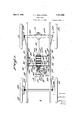
- Fig. 2 is a longitudinal section of the actuating mechanism.
- Fig. 8 is a transverse section on line 3-3 of Fig. 2.
- Fig. 4 is a transverse section on line 4-4 of Fig. 2.
- the brake pedal 21 is pivoted at 22 to some suitable part of the frame.
- the cross-web or stiffener 23 extends between the frame members 14, 15 and is fixedly connected thereto.
- a brake drum 24 is provided upon each of the wheels 10, 11, 12,13, and is so arranged that by traction upon the cables 25,
- Each of the cables 25, 26, 27, 28 passes over a tension pulley 29 which is pivoted at any suitable part of the frame at 30, and
- the tension springs 32 are connected to the respective pulleys to maintain the cables against sagging or slackness when the brakes are released; the tension of these springs is insufficient to counteract the releasing springs as customarily employed with the brake bands or blocks to release the same from their respective drums.
- the brake pedal 21 is connected by a link lever arms 36, as will be described hereinafter.
- a sleeve 37 is mounted to closely embrace the transmission shaft 16, and is keyed to turn thereWith by thefkey 38 in Figs. 3 and 4.
- This sleeve is held in-a proper position along the length-of this shaft 16 by the bushings 39 which are secured to theshaft by the set screws 40.
- Fixedly mounted by threading and setscrews 41 at theforward end of the sleeve is a' further bushing 42whi'ch serves as acounter-support for the coil spring 43 of heavy cross-section.
- a collar 44' which has a central forwardly extended circular section 45.
- a ball thrust bearing 46 is provided to re ceive the thrust of the end of the spring'43.
- thrust bearing is a bearing collar 44 which provides the fulcrums 44 for the lever arms 36 which carry rigidly therewith the cams 85; thiscollar is free to turn and to move longitudinally upon the sleeve; 7
- a series of collars 47 47, 47, 47 are provided for sliding movement longitudinally with regard to the sleeve 37, but held against rotation with regard thereto by the key 48: these collars 47 47*, 47, 47, therefore turn with the same speed as the transmission shaft at all times.
- Each of these collars 47 47", 47 47 is provided centrally with the longitudinally extending circular sections 49of the same diameter as the section 45.
- a'series ofapertures 50 to receive the coil springs 51.
- the tubes 52 are freely slidable within the apertures and around the springs, and serve to hold the springs 51 against lateraldisplacement.
- each face of the drums 53 carries a series of ball bearingsy54 mounted in the threaded bushings 55, and pressed outward by the springs 56, which act upon the followers 57-.
- a further collar 47 is disposed about the V "sleeve 37 adjacent the bearing collar 44, and
- the fibrev disk 58 has a pair of projectingffins 58 which engage about a guide 60 mountedon the stiffening web 23 of the frame, so that the disk is held against rotation about the axis of the transmission shaft 16, but is permitted to move longitudinally with regard thereto.
- Apin 59 in the periphery of each of the drums has oneof the cables 25, 26, 27,28 fastened thereto, so thatiwhen the drum isrro- 'tated'in either direction, the cable is Lurawn tight.
- the cams are provided with an upturned tip 85 as shown in Fig. 6,, to being carried beyond center.
- each of the drums 53 53, 53, 53 extend from the re 'spectivedrum substantially in a direction radial to the axis of the drums; and these cables are held without slack or traction upon the braking blocks or bands by the springs 32.
- the first effect of the compression of the collars toward each other is then to cause the collars 4 47 d to be pressed against the fibre disk 58 which is attached to the frame of vehicle as set forth above. This exerts aprimary braking action upon the transmission shaft, independently of any braking action upon the wheel brake drums.
- the springs 512.51 and 56 are compressed, and the collars move closer together; and finally pass into contact with the faces of the drums 53 53 53, 53; and cause the latter to rotate by frictional engagement. Since the springs 51 have substantially the same power, and the movement permitted each of the collars is uniform,the various drums will all be engaged at the same instant, and with the samefrictional pull.
- each of the drums pulls upon its attached cable 25, 26, 27, 28 respectively,'and tightens the brake shoe or band at the respective wheels 10, 11, 12, 13: hence the braking effort is uniformly at the several wheels, and since this effort is produced by individual drums each in frictional contact with separate faces of the collars, which in turn are driven positively, each drum will first take up any slack in its cable until the springs 82 are drawn tight, and the pulleys 29 are held in a fixed position by the spurs 31. This is done and collars, which at all times is uniform among the several drums.
- the cams When the brake pedal is released, the cams are returned to the original position by the pressures of the springs43, 51, 51*, and 56; and the drums center themselves in the space between the adjacent collars by the outward thrust of the ball bearings 54 by the springs 56, whereby the frictional engagement is eliminated, and the drums can turn back freely.
- the return springs of the brake mechanism release the brakes and retract the cables 25, 26, 27, 28 to the original position; and the springs 32 take up any existing slack, so that the next braking operation, begun in either direction of travel, may take place immediately upon actuation of the brake pedal.
- a braking effort may be produced with the engine in gear, in the same manner as before.
- the mechanism described above refers to the use of four drums to apply individually the brakes on all four wheels of a vehicle.
- Fig.7 a modified form of the apparatus, in which a plurality of brakes may be applied from a single drum.
- the drum 7 0 is provided at its periphery with a pin 71, which is connected by a link 72 with a crank arm 73 pivoted at 74 to the frame of the vehicle.
- the other arm of the crank is connected by a link 75 to the pulley 76, over which passes the cable 77 which is connected at each end to a brake band or shoe intheusual manner.
- the operation is substantially the same as'before: when the drum rotates, the
- a powerbrake for a vehicle having a rotating shaft, a'pair of collars surrounding and driven by the shaft, a drum mounted between said collars, a plurality of circum-' ferentially spaced springsto normally hold said collars separated from'said drum, means to press said collars into frictional contact with' said drum topr'oduce the, rotational movement of the latter, and a brake cable attached to said drum.
- a rotating shaft a collar'surr'ounding and driven by the shaft, a drum loosely mounted upon the shaft, a friction ,disk loosely mounted upon theshaft and held substantially against rotation with regard to the frame of the vehicle, a brake cable attached to said drum,means to press said collar, said drum and said disk into contact, whereby primarily a braking effect is produced upon said collar and secondarily a traction is produced by said drum upon said brake cable.
- a power brake a rotating shaft, a pluralityof collars, and a'plurality ofsdrums mounted upon the shaft, means to cause said" collars to rotate with the shaft, a device to bring said collars and'drums together'whereby thelatter are rotated frictionally by the former, a flexible means connecting each of said drums with a brake, and means to take up the slack in each of said flexible 7 means, wherebysaid cables are tensed equal- 1y movement ofsaid drums in 'either dia rotatingshaft, a plurality of collars keyed .to rotate with said shaft, adjacent collars keyed to rotate with said sleeve, means normally holding said collars separated, a plurality of drums disposed individually between pairs of said collars, spring-pressed ball hearings to hold said drums and collars norrn'allycout of frictional engagement, a safety spring mounted upon said sleeve, a thrust bearing, a supporting bushing adapted to slide upon the shaft
- actuating meansi 10 Ina power brake for a vhielenavifig a rotating shaft, a pair of collars surrounding and driven by the shaft, a drum mounted coaxially with and between said collars, a
- a power brake for a vehicle having a rotating shaft, a pair of collars surrounding and driven by the shaft, a drum mounted coaxially with and between said collars, a spring located and acting between said collars to normally hold said collars separated from each other by a greater distance than the axial thickness of said drum, said drum having passages extending between the end faces thereof, ball bearings located in said passages and a spring acting upon the ball bearings whereby the ball bearings are normally forced outward by said spring to space said drum from said collars and produce a substantially frictionless relationship between said drum and rollers, means to press said collars into frictional contact with said drum whereby said surfaces establish a frictional driving relationship whereby to rotate the drum, and a brake connection attached to said drum.
- a collar keyed on to rotate with said shaft, a drum about said shaft adjacent said collar, means'to hold said drum normally out of contact with said collar, means to resiliently bring said drum into frictional engagement with said collar whereby torotate the drum, and means to connect iii? drum to the brake mechanism of the ve- 13.
- a power brake for a vehicle having a rotating shaft, a pair of collars located on and keyed to rotate with said shaft, a drum disposed about said shaft between said collars, means to normally fhold said drum out of frictional driving contact with said collars, a spring adapted to bring said drum and collars into frictional driving contact, said means and spring in the normal position of the elements of said brake being balanced against each other so that the collars and drum are spaced one from another, and means to increase the tensionof said spring whereby a rotating shaft, a plurality of collars keyed to rotate with the shaft, said collars presenting adjacent spaced end faces and reduced portions, a drum journalled on said reduced portions and having end faces opposite the end faces of the collars, means to separate the drums and collars axially with respect to the shaft, means to bring the drums and collars together for driving contact, and a brake connection from said drum to the brake mechanism of the vehicle.
- a power brake for a vehicle having a rotating shaft, an axially movable collar and a fixed collar keyed to rotate with said shaft, a -drum mounted between said collars and coaxial with the shaft, a stop on said shaft spaced from said fixed collar, said movable collar and drum being mounted between said fixed collar and said stop, a spring between said stop and movable collar, means operating between the spring and movable collar to force the drums and collars together whereby to produce a driving relationship between said collars and drums, andmeans to connect said drum to the brake mechanism of the vehicle.
- a power brake for a vehicle having a rotating shaft, a collar fixed on said shaft, a stop fixed on said shaft and spaced from said collar, a drum mounted between said collar and stop, a spring between said stop and collar, means operating between the spring and collar to move said drum, and means to connect said drum to the brake mechanism of the vehicle.
- a power brake for a vehicle having a rotating shaft positively connected with a wheel ofthe vehicle, said vehicle having a brake and brake actuating means connected to said brake and to the frame, a drum, said brake means also having a connection to the drum at a point opposite the frame connection when the drum is in the unoperated position so that movement of the drum in either direction will actuate the brake means to apply the brake, a collar fixed to said shaft, means to bring said drum and collar together for the movement of said drum according to the direction of movement of the vehicle, and means to return said drum from operated to unoperated position.
Landscapes
- Engineering & Computer Science (AREA)
- Chemical & Material Sciences (AREA)
- Combustion & Propulsion (AREA)
- Physics & Mathematics (AREA)
- Fluid Mechanics (AREA)
- Transportation (AREA)
- Mechanical Engineering (AREA)
- Braking Arrangements (AREA)
Description
June 3, 1930. H.' SHALLCROSS I POWER BRAKE 7 Filed Sept. 5', 1925 s Sheets-Sheet 2 J 3, 1930. H. L. SHALLCRQSS 1,761,896
POWER BRAKE Filed Sept. :5, 1925 s Shee't s-Sht s Patented June 3, 1930- UNITED. STATES PATENT OFFICE- HERBERT L. SHALLCROSS, or PHILADELPHIA, PENNSYLVANIA rower. B KE Application filed September 3, 1925 Serial No. 54,194.
This invention relates to improvements in power brakes forveh1cles,'and more particularly to-the mechanism for. actuating the same.
Heretofore several proposals have been made for the installation of power brakes upon vehicles, by which the power of a driving-engine or the inertia of the vehicle itself was employed to tightena brake band or shoe 'upon a wheel or drum. These structures have had the disadvantage of requiring frequent manual adjustment of the connective cables or rods to compensate wear and stretching; and a similar adjustment with great care was required to prevent the application of one brake more than another. The customary location of such actuating de vices was such that they could be driven from the en ine, through some clutching system.
According to the present invention, a power brake actuating mechanism is pro video. which consists of a drum mounted upon a shaft connected positively with a ground wheel of the vehicle, so that as long as the vehicle is moving, the shaft is rotating, and the drum may be engaged for actuation of the brake. It is preferred to pro vide such a drum upon the transmission jshaftof'an automotive vehicle, at an appropriate point, so that the drum may be coupled for rotation by the'shaft by depression of the customary brake pedal ofthe vehicle. Further, compensating means are 7 provided between the shaft and the connective cables or rods, so that the actuating effort upon the. brakes proper may be equalized. vided to take up the slack of such connective cables or rods at all times, sothat the brake application is smooth and gradual, and not irregular and jerky. A further feature of the invention isthe provision of a transmission brake mechanism in connection with the aforesaid wheel brake mechanism. The structure is alsoprovided with a safety -means by which no seizing or binding is possible in the engagement of the several drums for actuation by the shaft. Another feature'is' the provision of spacing and bear ing means to prevent frictional dragging of of Fig. 2.
Inaddition thereto, means are pro the drum upon the shaft during normal propulsion of the vehicle. I
With these and other objects in view as will appear in the course of the following specification and claims, on the accompanying drawings: V r
Fig. 1 is a plan view of an automobile frame with the arrangement of the structure shown in diagrammatic presentation.
Fig. 2 is a longitudinal section of the actuating mechanism.
Fig. 8 is a transverse section on line 3-3 of Fig. 2.
Fig. 4 is a transverse section on line 4-4 of Fig. 2.
sal joint 17 at the rear end of the usual transmission housing 18 to the differential 19 mounted on the rear axle 20 to drive the rear wheels 11, 12. The brake pedal 21 is pivoted at 22 to some suitable part of the frame. The cross-web or stiffener 23 extends between the frame members 14, 15 and is fixedly connected thereto.
A brake drum 24 is provided upon each of the wheels 10, 11, 12,13, and is so arranged that by traction upon the cables 25,
26, 27, 28, the brake elements are drawn tight upon the drums, so that a braking action results.
Since the manner in which this movement occurs forms no part of the present invention, it need not be described in further detail.
Each of the cables 25, 26, 27, 28 passes over a tension pulley 29 which is pivoted at any suitable part of the frame at 30, and
have the stop elements 31 associated therewith to determine an end point of their movements when the respective cables are drawn tight. The tension springs 32 are connected to the respective pulleys to maintain the cables against sagging or slackness when the brakes are released; the tension of these springs is insufficient to counteract the releasing springs as customarily employed with the brake bands or blocks to release the same from their respective drums. I I
The brake pedal 21 is connected by a link lever arms 36, as will be described hereinafter.
A sleeve 37 is mounted to closely embrace the transmission shaft 16, and is keyed to turn thereWith by thefkey 38 in Figs. 3 and 4.
This sleeve is held in-a proper position along the length-of this shaft 16 by the bushings 39 which are secured to theshaft by the set screws 40.. Fixedly mounted by threading and setscrews 41 at theforward end of the sleeve isa' further bushing 42whi'ch serves as acounter-support for the coil spring 43 of heavy cross-section. ,FiXedly mounted on the rearw'ardfendof the sleeve is a collar 44'which has a central forwardly extended circular section 45.
A ball thrust bearing 46 is provided to re ceive the thrust of the end of the spring'43.
Disposed around the sleeve 37 adjacent this:
thrust bearing is a bearing collar 44 which provides the fulcrums 44 for the lever arms 36 which carry rigidly therewith the cams 85; thiscollar is free to turn and to move longitudinally upon the sleeve; 7
'Asshown in Fig. 2, a series of collars 47 47, 47, 47 are provided for sliding movement longitudinally with regard to the sleeve 37, but held against rotation with regard thereto by the key 48: these collars 47 47*, 47, 47, therefore turn with the same speed as the transmission shaft at all times. Each of these collars 47 47", 47 47 is provided centrally with the longitudinally extending circular sections 49of the same diameter as the section 45. In each of these collars is provided a'series ofapertures 50 to receive the coil springs 51. The tubes 52 are freely slidable within the apertures and around the springs, and serve to hold the springs 51 against lateraldisplacement. As the collars 47 approach each other, the tubes 52 enter the collars; and the relations of the several parts are soselected'that-before the tubes extei-lfdifrom the bottom of the cavity in one collar to the bottom of the adjacent collar, the two collars will havecome in contact at the end faces of the peripheralsections: in this :way a crushing of the tubes 52 is avoided.
Mounted in the peripheral grooves afiorded between each pair of collars arethe apertureddrums 53 53 53", 53 equal in number tothe number of brakes to be applied whose end faces are parallel-to and adapted to contact with the outer. end faces of the collars sections 49 and 45. In order to avoid great frictional losses, each face of the drums 53 carries a series of ball bearingsy54 mounted in the threaded bushings 55, and pressed outward by the springs 56, which act upon the followers 57-.
- A further collar 47 is disposed about the V "sleeve 37 adjacent the bearing collar 44, and
hasa central circular section 49like those of the collars 47 47*, 47 47. Mounted in the peripheral groove between thecollars 47 e and '47 is a. fibre friction'disk 58. The coil springs 51 mounted between these disks are like those at 51 between the other disks,- but preferablyare slightly weaker. The fibrev disk 58has a pair of projectingffins 58 which engage about a guide 60 mountedon the stiffening web 23 of the frame, so that the disk is held against rotation about the axis of the transmission shaft 16, but is permitted to move longitudinally with regard thereto.
. It is preferred to make the total force presented by the several springs 51, 51 slightly less than the force presented by the single safety spring 43, so that the movementfoccasioned by the cams,'as willjbe described hereinafter, will normally act substantially upon the collarsprings 56to causethecollars and drums to come into contact, before the sprlng 43 has been compressed to any great amount,
Apin 59 in the periphery of each of the drums has oneof the cables 25, 26, 27,28 fastened thereto, so thatiwhen the drum isrro- 'tated'in either direction, the cable is Lurawn tight. I
The cams are provided with an upturned tip 85 as shown in Fig. 6,, to being carried beyond center.
The method of operation of this mechanism 1 o is as follows: 7
In the normal runningcondition of the parts, the spring 43 and theseries of springs prevent the cam 51, 51 and 56 are withoutcompression. The
This condition of the parts is represented in r Fig. 2, in which it will be seen that the relative tensions of the springsmay be adjusted by the collars 42, and 44 When it is desired to apply a braking effort to the vehicle, the brake pedal 21 is depressed,
thus actuating the link 33, the crank 34, the link 35, and the lever arms 36 and the cams 85. The cams rotate about their pivots or fulcrums 44 and present their faces against the ball thrust bearing 46 andthe end collar 47", thus increasing the separation between the two latter elements. Since the spring 43 yields butslightly, and the groups of springs '51, 51 and 56 associated with the collars yield greatly, the collar '44 supporting the cams 85 and the lever arms 36 will move longitudinally upon the sleeve 37 and establish and maintain a central relation of the collar 44 in the space between the thrust bearing and the collar 47 e i The pressure of the cams upon the collar 47 will be transmitted therethrough to the succeeding collar 47 by the springs 51, and so on, so that the relative movement between each pair of collars 47 9, 47 47, 47*, etc. is substantially uniform; as mentioned above, the springs 51 ,'however, may be somewhat weaker than those at ,51'so that collars 47 47 clamp the disk 58 before anydrum is clamped.
The first effect of the compression of the collars toward each other is then to cause the collars 4 47 d to be pressed against the fibre disk 58 which is attached to the frame of vehicle as set forth above. This exerts aprimary braking action upon the transmission shaft, independently of any braking action upon the wheel brake drums.
In the longitudinal movement of the collars, the springs 512.51 and 56 are compressed, and the collars move closer together; and finally pass into contact with the faces of the drums 53 53 53, 53; and cause the latter to rotate by frictional engagement. Since the springs 51 have substantially the same power, and the movement permitted each of the collars is uniform,the various drums will all be engaged at the same instant, and with the samefrictional pull. Each of the drums pulls upon its attached cable 25, 26, 27, 28 respectively,'and tightens the brake shoe or band at the respective wheels 10, 11, 12, 13: hence the braking effort is uniformly at the several wheels, and since this effort is produced by individual drums each in frictional contact with separate faces of the collars, which in turn are driven positively, each drum will first take up any slack in its cable until the springs 82 are drawn tight, and the pulleys 29 are held in a fixed position by the spurs 31. This is done and collars, which at all times is uniform among the several drums.
When the brake pedal is released, the cams are returned to the original position by the pressures of the springs43, 51, 51*, and 56; and the drums center themselves in the space between the adjacent collars by the outward thrust of the ball bearings 54 by the springs 56, whereby the frictional engagement is eliminated, and the drums can turn back freely. The return springs of the brake mechanism release the brakes and retract the cables 25, 26, 27, 28 to the original position; and the springs 32 take up any existing slack, so that the next braking operation, begun in either direction of travel, may take place immediately upon actuation of the brake pedal.
wheels, and the engine is turning over, a braking effort may be produced with the engine in gear, in the same manner as before.
a The above operation occurs in either direction of motion of the vehicle, since in the normal or non-braking position, the cable is attached to the pin 59 of the drum and'extends therefrom in a line passing substantially through the axis of the 'shaft 16. The movement of the drum in either direction will cause a traction upon the cable, since no winding up of the cable upon the drum is contemplated, the movement of the cable necessary for braking normally beingless than a quarter circumference of the drum.
The mechanism described above refers to the use of four drums to apply individually the brakes on all four wheels of a vehicle.
'The same type of mechanism may likewise be employed with fewer drums to apply only the brakes on two wheels, without change of the principle of construction.
In Fig.7 is shown a modified form of the apparatus, in which a plurality of brakes may be applied from a single drum. In this case the drum 7 0 is provided at its periphery with a pin 71, which is connected by a link 72 with a crank arm 73 pivoted at 74 to the frame of the vehicle. The other arm of the crank is connected by a link 75 to the pulley 76, over which passes the cable 77 which is connected at each end to a brake band or shoe intheusual manner. The operation is substantially the same as'before: when the drum rotates, the
link 72 is pulled, which through the crank 73 and the link 75 pulls upon the pulley 76 and causes an equalized tightening of the cable 77 at both ends and thus an application of the k I I I I is. a. .1
Obvious changes may be made in the form of construction without departing from the scope of the appended claims.
Having thus fully described the invention, what I claim is:
1. In a powerbrake for a vehicle having a rotating shaft, a'pair of collars surrounding and driven by the shaft, a drum mounted between said collars, a plurality of circum-' ferentially spaced springsto normally hold said collars separated from'said drum, means to press said collars into frictional contact with' said drum topr'oduce the, rotational movement of the latter, and a brake cable attached to said drum.
. 2. In apower brake fora vehicle having.
a rotating shaft, a collar'surr'ounding and driven by the shaft, a drum loosely mounted upon the shaft, a friction ,disk loosely mounted upon theshaft and held substantially against rotation with regard to the frame of the vehicle, a brake cable attached to said drum,means to press said collar, said drum and said disk into contact, whereby primarily a braking effect is produced upon said collar and secondarily a traction is produced by said drum upon said brake cable.
3. In apower brake, a rotating shaft, a pluralityof collars, and a'plurality ofsdrums mounted upon the shaft, means to cause said" collars to rotate with the shaft, a device to bring said collars and'drums together'whereby thelatter are rotated frictionally by the former, a flexible means connecting each of said drums with a brake, and means to take up the slack in each of said flexible 7 means, wherebysaid cables are tensed equal- 1y movement ofsaid drums in 'either dia rotatingshaft, a plurality of collars keyed .to rotate with said shaft, adjacent collars keyed to rotate with said sleeve, means normally holding said collars separated, a plurality of drums disposed individually between pairs of said collars, spring-pressed ball hearings to hold said drums and collars norrn'allycout of frictional engagement, a safety spring mounted upon said sleeve, a thrust bearing, a supporting bushing adapted to slide upon the sleeve, a cam carried by said 4; In a power brake for a vehicle having bushing and in operative contact with said thrust bearing' and the endcollar, means eonnecting the brake pedal of the vehicle to" actu ate said cam, a cable extending from "ea'c'hof said drums to a'br'ake mechanism of the vehisaid cables, whereby said cam upon actua;.- tion' from said pedal presses said collars' an d drums into operative frictional contact against the thrust of said safety spring, to efiect atraction of said cables.
.cle,and means to take'up the slack'in each of In a P wer brake for avehicle havin arotating shaft, a collar surrounding and driven by the shaft, a drum coaxial'with said shaft and having a face in complemental relation to the face of said collar, ball bearings disposed to normally separate said faces whereby said collar may moveindependently of said drum, meanstopress.said drum and collar into frictional engagement with each other whereby the latter is rotatedby,
former, a brake cable connected to said drum, and means to hold said bearings whereby 7 said fritcional engagement may be permit; ted to the exclusion of said independent movement. t o H 7 In apower brake for a vehicle having a rotating shaft, a plurality of collars sur% rounding and drivenby said shaft, a drum coaxialwith said shaft andjh'a i g f d h c in complemental relation to ajfac'efof one "of' said collars,'ball beari gs disposed to nor} mally separate said faces whereby'said col 7 lars may move independently of said drum, spring means tohold saidbearings such position, means to press said drum andc'ol-I lars into frictional engagement with each 8. In a power brake for a vehicle'having a plurality'of brakes. and a rotating shaft, a
other against the action of said spring means, and a brake cable connected to said drum. o 10% i a plurality of drumsloosely. mounted about; said shaft, afdevice connected to each'of said drums to actuate each its respective brake, means to frictionally drive said drums col-1 lectively from said shaft whereby each drum may move'a distance varying fromthatof another until substantially the same braking effort is produced by said devices, and means including a spring to resiliently bring said driving means into operative condition;
9. In a power brake for avehiclehaving a plurality of"brakes and a rotating shaft, a
frictional driving member driven by said ;f
shaft, devices connected to each of said brakes and including a balancing mechanism whereby equal braking e'fiorts are delivered to each of said brakes, friction means adapted to cause the actuation ofsaid-"devices from said rnember, resilient q means acting upon said friction means to produce the actuation; V
of said devices from said member, and means? to free said devices frornactuation byl saidjr. member upon release ofsaid actuating meansi 10. Ina power brake for a vhielenavifig a rotating shaft, a pair of collars surrounding and driven by the shaft, a drum mounted coaxially with and between said collars, a
spring located and acting between said col- 5 lars to normally hold said collars separated from each other by a greater distance than the axial thickness of said drum, spring pressed means carried by said drum and acting upon said collars to hold the end surfaces of the drums separated from the adjacent surfaces of the collars, means to press said collars into frictional contact with said drum whereby said surfaces establish a frictional driving relationship whereby to rotate the drum, and a brake connection attached to said drum.
11. In a power brake for a vehicle having a rotating shaft, a pair of collars surrounding and driven by the shaft, a drum mounted coaxially with and between said collars, a spring located and acting between said collars to normally hold said collars separated from each other by a greater distance than the axial thickness of said drum, said drum having passages extending between the end faces thereof, ball bearings located in said passages and a spring acting upon the ball bearings whereby the ball bearings are normally forced outward by said spring to space said drum from said collars and produce a substantially frictionless relationship between said drum and rollers, means to press said collars into frictional contact with said drum whereby said surfaces establish a frictional driving relationship whereby to rotate the drum, and a brake connection attached to said drum. i
12. In a power brake for a vehicle having a rotating shaft, a collar keyed on to rotate with said shaft, a drum about said shaft adjacent said collar, means'to hold said drum normally out of contact with said collar, means to resiliently bring said drum into frictional engagement with said collar whereby torotate the drum, and means to connect iii? drum to the brake mechanism of the ve- 13. In a power brake for a vehicle having a rotating shaft, a pair of collars located on and keyed to rotate with said shaft, a drum disposed about said shaft between said collars, means to normally fhold said drum out of frictional driving contact with said collars, a spring adapted to bring said drum and collars into frictional driving contact, said means and spring in the normal position of the elements of said brake being balanced against each other so that the collars and drum are spaced one from another, and means to increase the tensionof said spring whereby a rotating shaft, a plurality of collars keyed to rotate with the shaft, said collars presenting adjacent spaced end faces and reduced portions, a drum journalled on said reduced portions and having end faces opposite the end faces of the collars, means to separate the drums and collars axially with respect to the shaft, means to bring the drums and collars together for driving contact, and a brake connection from said drum to the brake mechanism of the vehicle.
15. In a power brake for a vehicle having a rotating shaft, an axially movable collar and a fixed collar keyed to rotate with said shaft, a -drum mounted between said collars and coaxial with the shaft, a stop on said shaft spaced from said fixed collar, said movable collar and drum being mounted between said fixed collar and said stop, a spring between said stop and movable collar, means operating between the spring and movable collar to force the drums and collars together whereby to produce a driving relationship between said collars and drums, andmeans to connect said drum to the brake mechanism of the vehicle.
16. In a power brake for a vehicle having a rotating shaft, a collar fixed on said shaft, a stop fixed on said shaft and spaced from said collar, a drum mounted between said collar and stop, a spring between said stop and collar, means operating between the spring and collar to move said drum, and means to connect said drum to the brake mechanism of the vehicle.
17. In a power brake for a vehicle having a rotating shaft positively connected with a wheel ofthe vehicle, said vehicle having a brake and brake actuating means connected to said brake and to the frame, a drum, said brake means also having a connection to the drum at a point opposite the frame connection when the drum is in the unoperated position so that movement of the drum in either direction will actuate the brake means to apply the brake, a collar fixed to said shaft, means to bring said drum and collar together for the movement of said drum according to the direction of movement of the vehicle, and means to return said drum from operated to unoperated position.
In testimony whereof, I aflix my signature.
HERBERT L. SHALLGROSS.
resiliently to bring said collars and drum into frictional engagement with one'another, and means to connect said drum to the brake mechanism of the vehicle.
14. In a powerbrake for a vehicle having
Priority Applications (1)
| Application Number | Priority Date | Filing Date | Title |
|---|---|---|---|
| US54194A US1761896A (en) | 1925-09-03 | 1925-09-03 | Power brake |
Applications Claiming Priority (1)
| Application Number | Priority Date | Filing Date | Title |
|---|---|---|---|
| US54194A US1761896A (en) | 1925-09-03 | 1925-09-03 | Power brake |
Publications (1)
| Publication Number | Publication Date |
|---|---|
| US1761896A true US1761896A (en) | 1930-06-03 |
Family
ID=21989373
Family Applications (1)
| Application Number | Title | Priority Date | Filing Date |
|---|---|---|---|
| US54194A Expired - Lifetime US1761896A (en) | 1925-09-03 | 1925-09-03 | Power brake |
Country Status (1)
| Country | Link |
|---|---|
| US (1) | US1761896A (en) |
-
1925
- 1925-09-03 US US54194A patent/US1761896A/en not_active Expired - Lifetime
Similar Documents
| Publication | Publication Date | Title |
|---|---|---|
| US10690200B2 (en) | Manually-actuated brake system using magnetorheological fluid clutch apparatus | |
| US1761896A (en) | Power brake | |
| US1674751A (en) | Equalized braking mechanism for single-track vehicles | |
| US1531926A (en) | Automatic governor for the brakes of motor and railway wheels and other rotary devices | |
| US2532670A (en) | Braking system for motor vehicles | |
| US1575426A (en) | Brake mechanism | |
| US3292873A (en) | Winches for paying out cables | |
| US1673713A (en) | Automobile brake | |
| US1858257A (en) | Motor car axle and brake | |
| US1957148A (en) | Device for reducing the stresses upon films in cinematographic apparatus | |
| US1634186A (en) | Braking of motor and other vehicles | |
| US820102A (en) | Automobile. | |
| US2051904A (en) | Brake | |
| US2144024A (en) | Brake | |
| US1431169A (en) | Speed regulator for motor vehicles | |
| US1411664A (en) | Vehicle brake | |
| US2468652A (en) | Control instrumentality | |
| US1968185A (en) | Automobile brake | |
| US1866791A (en) | Brake system | |
| US1306652A (en) | wilson | |
| US1502111A (en) | Brake mechanism for road vehicles | |
| US988464A (en) | Brake. | |
| US978880A (en) | Variable-speed gearing. | |
| GB139818A (en) | An improved systems and/or apparatus for automatically governing or controlling the speed of any rotary device | |
| US1635572A (en) | Brake |