US1761885A - Liquid-dispensing apparatus - Google Patents
Liquid-dispensing apparatus Download PDFInfo
- Publication number
- US1761885A US1761885A US104463A US10446326A US1761885A US 1761885 A US1761885 A US 1761885A US 104463 A US104463 A US 104463A US 10446326 A US10446326 A US 10446326A US 1761885 A US1761885 A US 1761885A
- Authority
- US
- United States
- Prior art keywords
- meter
- lever
- liquid
- valve
- pointer
- Prior art date
- Legal status (The legal status is an assumption and is not a legal conclusion. Google has not performed a legal analysis and makes no representation as to the accuracy of the status listed.)
- Expired - Lifetime
Links
Images


Classifications
-
- B—PERFORMING OPERATIONS; TRANSPORTING
- B67—OPENING, CLOSING OR CLEANING BOTTLES, JARS OR SIMILAR CONTAINERS; LIQUID HANDLING
- B67D—DISPENSING, DELIVERING OR TRANSFERRING LIQUIDS, NOT OTHERWISE PROVIDED FOR
- B67D7/00—Apparatus or devices for transferring liquids from bulk storage containers or reservoirs into vehicles or into portable containers, e.g. for retail sale purposes
- B67D7/06—Details or accessories
- B67D7/08—Arrangements of devices for controlling, indicating, metering or registering quantity or price of liquid transferred
- B67D7/30—Arrangements of devices for controlling, indicating, metering or registering quantity or price of liquid transferred with means for predetermining quantity of liquid to be transferred
Definitions
- Thisinvention relates to liquid dispensing apparatus and more particularly to-apparatus fordispensing gasoline.
- One object is to provide a dispensing apparatus employing a meter as one of its elements, the meter delivering direct to a dispensing valve. Another object is to provide dial. pointers on the meter which can readily I be moved-back to zero after each lot of gasoline is dispensed. A further object is to provide quantity setting means which can be set for the number of gallons desired and which, when the set number of" gallons has been measured bythe meter, returns to zero position and automatically closesthe dispensing valve. A still further object is'to provide 1 means for setting the dispensing valve in either wholly or partly open-position to provide either a full or restricted flowv of gasoline.
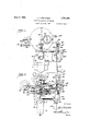
- Figure 1 is a front elevati9n,..of the apparatus
- Figure 2 is a plan view: of Figure 1;
- Figure 3 is a section on line'3-3 of Fig ure/1; I I
- Figure 4 is an enlarged showing of a per Figure 5 is a section of a portion of the apparatus on line 5-5 of Figure 4;
- Figure 6 is a section on line 6"-6 of Figure 4:;
- Figure 7 is an enlarged right hand side elevation of a portion of the apparatus
- Figure 8 is an enlarged plan view of a por tion of th setting mechanism
- Quantity measuring-means in'the form of a meter 1 (Fig. 1 is connected by pipe 2 (Fig. 10) to a dispensing valve 3.
- This dispensing valve 3 is normally held closed by spring 4 as shown, but when stem 5 is forced down by arm 6 carried by rock shaft 7, the valve is opened to of nipple 8. v
- the outer portion of shaft ,a10 carries pointer 13 for indicating gallons and fractions thereof, while pointer 14; on the outer portion of shaft 11 indicates up'to anumber of gallons.
- the outer POIlZIOD. of shaft 10 comprises a shaft member 16 and two'hub members 17,
- Hub member 18 is freely rotatable on shaft member 1 6 and carries pointer 13 with a central hole 19 (Fig. 11) freely fitting over shaft member 16, the pointer being secured to through slots 2L (Fig. 11) Screw 22 secured end of shaft member 16 holds cover 23, spring 24 and thrust washer 25 in position.
- hub members 17, 18 have opposed friction cone clutch faces 26.
- Member 17 is slidable longitudinally thereon in any desired manner. Member 17 is normally forced into clutching engagement with member 18 by a ⁇ relatively strong spring 27 engaged against pin 28. Spring-24 is relatively weak and is therefore compressed by strong spring 27 until the central area of pointer 31 thrusts against cover 23. The .function of spring24: will be hereinafter pointed out.
- shaft 11 comprises a shaft member 29 and two hub members 30 31.
- Hub member ,31 is I freely rotatable on shaft member 29 and carrier pointer 14 fixed thereto by screws 32. Heads of screws 32 engage against thrust washer 33 held in place by screw.34 secured in end of shaft member 29.
- -Hub member is slidable longitudinally of shaft member 29 and may be secured non-rotatablythereon in any desired manner.”
- Member 30 is normally forced into clutching engagement with member 31 by a spring 36 engaged against pin 37.
- a cam 46 is secured to hub Band has a V-shaped portion 47 pointed oppositely to the pointof pointer 13. Opposite V-shaped portion 47 is a V-shaped notch 48. Pivoted at 49 on frame 38 is a lever'50 weighted at 51 and having a hardened V-shaped block 52 adapted to fit notch 48. Disc 53 on the hub weighted lever the pointer at exactly zero.
- Guide disc 61 aids in keeping lever 55 in properposition on cam 60.
- levers or arms 66, 67 havingtheir outer ends normally held down by sprin s 68, 69 secured to depending portions 70, 1 of frame 38.
- the movement of levers 66, 67 is limited by abutments 7 2,7 3.
- the inner ends 78 being in such position that it strikes lever 79 by springing downward, lever 67 then springing upward to carry and retain hammer 78 out of contact with lever 79. 1
- a stud shaft 81 Secured to frame portion 80 is a stud shaft 81. Pivoted at 7 9 is lever 79, which is normally pressed upward against abutment 82 by spring 83 mounted in barrel 84 secured on frame portion 80.
- Lever 79 has setting pawl- 85 adapted to normally engage one of a plu: rality of ratchet studs 86 on setting wheel 87 .journalled on stud shaft 81.
- Finger 108 is secured to frame portion 80 to act as a backing for pawl 85.
- a guide plate 88 abuts against shoulder 89 on stud shaft 81' and has fingers90, 91, one on each side of barrel 84 to prevent plate 88 from turning on shaft 81.
- Between plate 88and wheel 87 is a coil spring 92 having one end securedto shaft 81 at 93 and the other end bent. at 94 to engage any one of a plurality of pins 95.
- Setting wheel87 carries numerals on its edge 96 visibleat zero position 97 (Fig. 1) when in use. By turning wheel 87 clockwise. (Fig. 1.) by means of handle 98 the ratchet studs'86 depress pawl lever 79 as they ride overpawl 85, the lever 79 promptly rising to posltion again by action of spring 83.
- ivoted at 99 is a set' and release pawl 100.
- an operating lever 101 having a.tooth 102adapted to engageeither of notches 103, 104 on pawl'lOO.
- the other endof pawl 100 has acam face 105'and a locking face 106.
- Wheel 87 has a pin 107 which, when the setting Wheel returns to zero as will be later described, first strikes camface 105'to release lever 101'tl1ereby closing the dispensing valve,-then engages I face 106 to stop the setting wheel to indicate zero.
- numeral five would show at 97 (Fig. 1) But when the first gallon was dispensed, the hand 13 had made one complete revolution back to zero, hand 14 indicated one gallon and the setting wheel had moved so that numeral 4 replaced numeral 5.. This action of hand 13 is repeated until hand 14 indicates five gallons and zero appears on the setting wheel at 97. As zero appears at 97, pin 107 depresses cam face 105 and raises notch 103 (or 104') out of engagement with the tooth 102, whereupon spring 4 closes the dispensing valve 3 and swingslever 101 to position shown in Fig. 7. It will be seen that valve opening lever 101 with tooth 102 will not engage with notch 103 or 104 until setting wheel 87 has been set to some numeral.
- quantity measuring means having a shaft member, a pair of clutch members mounted to move longitudinally of the shaft member, a lever adjacent one clutch member, an arm on the one clutch member adapted during rotation of the one clutch member to engage the lever while the clutch members are intereng'aged,
- a meter In a liquid dispensing apparatus, a meter, a valve in the meter line adapted to be closed when a predetermined quantity of liquid has passed through said meter, a quantity setting mechanism adapted to be actuated while the liquid is passing through the meter, means independent of the meter for actuating the setting mechanism, said setting mechanism causing the closing of said valve at a predetermined position of said settmg mechanism, and means operable by the meter to cause the actuation of said setting mechanism. 7 a
- a quantity setting mechanism com prising a wheel under spring tension, an es capement for holding said wheel, means actu- I ated by the meter for operating the escapement, and means released by the setting mechanism for closing the valve.
- a valve in the meter line ada ted to close when a predetermined amount 0 liquid has passed through the meter a quantity setting mechanism comprising an individual power means for actuating it, means actuated by the meter for causing the power means of the quantity setting mechanism to act, and means associated with the quantity setting mechanism for causing the valve to close.
- a setting mechanism comprising a wheel provided with a peripheral dial, the indicia on which is adapted to be exposed to view, spring means for advancing the wheel, means 'for' permitting the advance of the wheel step by step during the operation of the meter, and connections between the wheel and valve to ac complish the closing of the valve when the wheel assumes a predetermined position.
- a meter In a liquid dispensing apparatus, a meter, a pair of stub shafts, pointers rotating with said shafts, dials associated with said pointers, means for releasing the pointers from the shafts whereby they may assume a predetermined position with respect to said dials, a quantity setting mechanism, means released from one of said shafts for advancing the setting mechanism step by step, a
- valve for stopping the flow of liquid through said meter, and means controlled by said setting mechanism for causing said valve to a close when the setting mechanism has advanced to a predetermined position.
- a meter In a liquid dispenslng apparatus, a meter, a valve in the meter line, a quantity setting mechanism controlling said valve, means for advancing said setting mechanism,
- step by step and means for actuating said advancing means, the meter operating upon said actuating means to store power therein and release the same for its actuation of said advancing means.
Landscapes
- Engineering & Computer Science (AREA)
- Physics & Mathematics (AREA)
- Mathematical Physics (AREA)
- Theoretical Computer Science (AREA)
- Mechanical Engineering (AREA)
- Devices For Dispensing Beverages (AREA)
Description
June 3, 1930. GRQETKEN 1,761,885
LIQUID DISPENSING APPARATUS Filed April 24, 1926 4 Sheets-Sheet 1' /0/ J Jmmtoa I W J55): Graeme/a June 3, 1930. J. J. GROETKEN 1,761,885
LIQUID DI SPENS ING APPARATUS Filed April 24, 1926 4 Sheets-Sheet 3 gwumtom J25. GroetKen,
PM 3 M June 3, 1930. J. J. GROETKEN" LIQUID DISPENSING APPARAT S 4 Sheets-Sheet Filed April 24, 1926 gmmtoc J5 IG rroefKem 35 tion of Figure 2;
Patented June. 3, 1930 PATENT oFFicE.
' aosnrn i enonrxmr, or AURORA, rumors LIQUID-DISPENSING APPARATUS Application filed .April 24, 1926. Serial No. 104,403.
Thisinvention relates to liquid dispensing apparatus and more particularly to-apparatus fordispensing gasoline. I
One object is to provide a dispensing apparatus employing a meter as one of its elements, the meter delivering direct to a dispensing valve. Another object is to provide dial. pointers on the meter which can readily I be moved-back to zero after each lot of gasoline is dispensed. A further object is to provide quantity setting means which can be set for the number of gallons desired and which, when the set number of" gallons has been measured bythe meter, returns to zero position and automatically closesthe dispensing valve. A still further object is'to provide 1 means for setting the dispensing valve in either wholly or partly open-position to provide either a full or restricted flowv of gasoline.
5 Other objects and advantages of the invention will hereinafter appear in the following description and the novel features thereof will be particularly pointed out in the appended claims. I
Like letters of reference indicate like parts throughout the several figures of the drawings, in which Figure 1 is a front elevati9n,..of the apparatus;
Figure 2 is a plan view: of Figure 1; I Figure 3 is a section on line'3-3 of Fig ure/1; I I
Figure 4; is an enlarged showing of a per Figure 5 is a section of a portion of the apparatus on line 5-5 of Figure 4; Figure 6 is a section on line 6"-6 of Figure 4:;
Figure 7 is an enlarged right hand side elevation of a portion of the apparatus;
Figure 8 is an enlarged plan view of a por tion of th setting mechanism;
Figure is a section online 9-. 9 of Fig-' ure 7 Figure 10 is a section of the dispensing valve on line 10-10 of Figure'2; Fi ure 11,.is a front elevation, of an adjusta 1e pointer; and Figure 12 is a section of a portion of the Figure 7 It will be understood that the invention setting pawl mechanism on line 12 12 of may be varied in its details of construction and that the specific embodiment illustrated and described herein is only indicative thereof.
Quantity measuring-means in'the form of a meter 1 (Fig. 1 is connected by pipe 2 (Fig. 10) to a dispensing valve 3. This dispensing valve 3 is normally held closed by spring 4 as shown, but when stem 5 is forced down by arm 6 carried by rock shaft 7, the valve is opened to of nipple 8. v
Extending up' from meter 1 is a shaft 9 (Figs. 2, 5) which through suitable gearing actuates shafts 10, 11, 12 (Figs. 4, 5) re-' 'spectivelycarrying indicating pointers 13,
14 and total index 15. I
The outer portion of shaft ,a10 carries pointer 13 for indicating gallons and fractions thereof, while pointer 14; on the outer portion of shaft 11 indicates up'to anumber of gallons.
The outer POIlZIOD. of shaft 10 comprises a shaft member 16 and two'hub members 17,
- 18/ Hub member 18 is freely rotatable on shaft member 1 6 and carries pointer 13 with a central hole 19 (Fig. 11) freely fitting over shaft member 16, the pointer being secured to through slots 2L (Fig. 11) Screw 22 secured end of shaft member 16 holds cover 23, spring 24 and thrust washer 25 in position.
permit flow of liquid out hub member 18 by screws 20. To permit the pointer to be adjusted so it will properlypomt to zero, screws 20 preferably pass The hub members 17, 18 have opposed friction cone clutch faces 26. Member 17 is slidable longitudinally thereon in any desired manner. Member 17 is normally forced into clutching engagement with member 18 by a\ relatively strong spring 27 engaged against pin 28. Spring-24 is relatively weak and is therefore compressed by strong spring 27 until the central area of pointer 31 thrusts against cover 23. The .function of spring24: will be hereinafter pointed out.
The outer portion of shaft 11 comprises a shaft member 29 and two hub members 30 31. Hub member ,31 is I freely rotatable on shaft member 29 and carrier pointer 14 fixed thereto by screws 32. Heads of screws 32 engage against thrust washer 33 held in place by screw.34 secured in end of shaft member 29. -Hub member is slidable longitudinally of shaft member 29 and may be secured non-rotatablythereon in any desired manner." Member 30 is normally forced into clutching engagement with member 31 by a spring 36 engaged against pin 37. Hub
- which latter is engagedby arm 42 secured I on rock shaft 43 carrying operating lever or handle 44, for which purpose the release fork '41 is provided with an extension (shown in by additional mechanismas will now be described. A cam 46 is secured to hub Band has a V-shaped portion 47 pointed oppositely to the pointof pointer 13. Opposite V-shaped portion 47 is a V-shaped notch 48. Pivoted at 49 on frame 38 is a lever'50 weighted at 51 and having a hardened V-shaped block 52 adapted to fit notch 48. Disc 53 on the hub weighted lever the pointer at exactly zero.
18 guides lever in properposition on cam 46. When pointer 13 points downwardly V-point 47 of the cam 46 points upward, and V-point of block 52 ress'ing on one side or the other of .V-portion of 'cam 46 starts pointer swinging toward zero, the remaining movement of pointer toward zero being ac-.
complished by counterweight 45. When the pointer arrives near zero, V-block 52 of 51) enters'notch 48 and'stops Pointer 14 is normally swun to zero by counterweight 54 securedto hu 31. Lever 55 pivoted at 56 and having V-sliaped block 57 coacts with V-shaped notch 58 and V- shaped portion 59 on cam 60 to swing and stop pointer 14 at zeroin a way similar to the way pointer 13 is swung andstopped by corresponding'parts previously described.
Secured to hub member 18 is .anarm 62 having pin 63. Pivoted to frame38 at 64,-
65, are levers or arms 66, 67 'havingtheir outer ends normally held down by sprin s 68, 69 secured to depending portions 70, 1 of frame 38. The movement of levers 66, 67 is limited by abutments 7 2,7 3. The inner ends 78 being in such position that it strikes lever 79 by springing downward, lever 67 then springing upward to carry and retain hammer 78 out of contact with lever 79. 1
. Secured to frame portion 80 is a stud shaft 81. Pivoted at 7 9 is lever 79, which is normally pressed upward against abutment 82 by spring 83 mounted in barrel 84 secured on frame portion 80. Lever 79 has setting pawl- 85 adapted to normally engage one of a plu: rality of ratchet studs 86 on setting wheel 87 .journalled on stud shaft 81. Finger 108 is secured to frame portion 80 to act as a backing for pawl 85. A guide plate 88 abuts against shoulder 89 on stud shaft 81' and has fingers90, 91, one on each side of barrel 84 to prevent plate 88 from turning on shaft 81. Between plate 88and wheel 87 is a coil spring 92 having one end securedto shaft 81 at 93 and the other end bent. at 94 to engage any one of a plurality of pins 95.-
Setting wheel87 carries numerals on its edge 96 visibleat zero position 97 (Fig. 1) when in use. By turning wheel 87 clockwise. (Fig. 1.) by means of handle 98 the ratchet studs'86 depress pawl lever 79 as they ride overpawl 85, the lever 79 promptly rising to posltion again by action of spring 83.
If wheel 87 isturned to produce more than a certain tension on spring 92 the end 94 slips from oneto another of pins 95, thereby relievmg any excesstenslonon the spr ng.
ivoted at 99 is a set' and release pawl 100. w
Secured on shaft 7 is an operating lever 101 having a.tooth 102adapted to engageeither of notches 103, 104 on pawl'lOO. The other endof pawl 100 has acam face 105'and a locking face 106. When tooth 102 is engaged in notch 104 the valve will be fully open and will give a maximum rate of flow'of liquid. Wheel 87 has a pin 107 which, when the setting Wheel returns to zero as will be later described, first strikes camface 105'to release lever 101'tl1ereby closing the dispensing valve,-then engages I face 106 to stop the setting wheel to indicate zero.
Operation. By means of pressing down lever 44 both pointers will he made to stand at zero as previously described. By handle 98 setting Wheel 87 is turned clockwise until the desired number of gallons is indicated at 97-( Fig. 1). Lever 101 is then forced inward byhand until tooth 102 engages notch 103 for a restricted flow, or notch 104 for a full flow of liquid. This positioning ofthe lever 101 opens the dispensing valve against action of spring'4. Liquid then passes through me-' ter 1 by means of either power, hand, or air operation as described. As the liquid passes a through the meter 1, pipe 2 and dispensing valve 3, by means of shaft 9 and other mechanism previously described, the pointers 13,
14 move to indicate the amount of liquid pass-- were originally set to-dispense five gallons,
numeral five would show at 97 (Fig. 1) But when the first gallon was dispensed, the hand 13 had made one complete revolution back to zero, hand 14 indicated one gallon and the setting wheel had moved so that numeral 4 replaced numeral 5.. This action of hand 13 is repeated until hand 14 indicates five gallons and zero appears on the setting wheel at 97. As zero appears at 97, pin 107 depresses cam face 105 and raises notch 103 (or 104') out of engagement with the tooth 102, whereupon spring 4 closes the dispensing valve 3 and swingslever 101 to position shown in Fig. 7. It will be seen that valve opening lever 101 with tooth 102 will not engage with notch 103 or 104 until setting wheel 87 has been set to some numeral.
Changes in the details of construction may be resorted to without .departing from the spirit of the invention as defined by the ap-' the invention, what is cam has a notchopposite its V-shaped point adapted to be engaged by the pressing means to properly locate the indicating pointer at zero.
3. The combination of claim 1 in which the I cam' has a V-shaped notch opposite its 'V- shaped point-adapted to be engaged by a similar shaped part on the .pressingmeans to properly locate the indicating .pointer at zero.
4. The combination of claim 1 in which the cam has a notch opposite its 'V-shaped'point adapted to be engaged by the pressing means to properly locate the indicating pointer at zero, and means for adjustably securing the indicating pointer to the shaft.
3 5. In a liquid dispensing apparatus, quantity measuring means having a shaft member, a pair of clutch members mounted to move longitudinally of the shaft member, a lever adjacent one clutch member, an arm on the one clutch member adapted during rotation of the one clutch member to engage the lever while the clutch members are intereng'aged,
- means for moving the other clutch member,; and means for moving the one clutch member axially on the shaft while the clutch members are disengaged to move the arm out of possible engagement with the lever during the rotation of the one clutch member.
6. The combination of claim 5 in which the means for moving the one. clutch member axially normally yieldably tends to produce such movement. 1
- 7.. The combination of claim 5 in which means normally yieldably holds the clutch ing valve normally held closed by yielding 7 means, avalve lever for forcing the valve open and setting it in open position, trip means intermediate the wheel and lever, one end of the trip means having means for en gaging the lever, and the other end having a cam face adapted to be engaged by the arm of the setting means to release the other end pf the trip means from engagement with the ever.
9. The combination of claim 8 which the trip means is a pivoted member.
10. The combination of claim 8 in which the trip means hasan abutment adjacent the cam face to stop the arm with the settin means in zero position.
11. In a liquid dispensing apparatus, a meter, a valve in the meter line adapted to be closed when a predetermined quantity of liquid has passed through said meter, a quantity setting mechanism adapted to be actuated while the liquid is passing through the meter, means independent of the meter for actuating the setting mechanism, said setting mechanism causing the closing of said valve at a predetermined position of said settmg mechanism, and means operable by the meter to cause the actuation of said setting mechanism. 7 a
12. In a liquid dispensing apparatus embodying a meter and a valve in the meter line adapted to be closed when a predetermined quantity of liquid has passed through said meter, a quantity setting mechanism com prising a wheel under spring tension, an es capement for holding said wheel, means actu- I ated by the meter for operating the escapement, and means released by the setting mechanism for closing the valve. i
1.3. In a liquid dispensing apparatus, a
:meter, a valve in the meter line ada ted to close when a predetermined amount 0 liquid has passed through the meter, a quantity setting mechanism comprising an individual power means for actuating it, means actuated by the meter for causing the power means of the quantity setting mechanism to act, and means associated with the quantity setting mechanism for causing the valve to close.
14 In a liquid dispensing apparatus embodying a meter and a discharge valve adapted to be closed after a predetermined quantity of liquid has'been discharged, a setting mechanism comprising a wheel provided with a peripheral dial, the indicia on which is adapted to be exposed to view, spring means for advancing the wheel, means 'for' permitting the advance of the wheel step by step during the operation of the meter, and connections between the wheel and valve to ac complish the closing of the valve when the wheel assumes a predetermined position.
15. In a liquid dispensing apparatus, a meter, a pair of stub shafts, pointers rotating with said shafts, dials associated with said pointers, means for releasing the pointers from the shafts whereby they may assume a predetermined position with respect to said dials, a quantity setting mechanism, means released from one of said shafts for advancing the setting mechanism step by step, a
valve for stopping the flow of liquid through said meter, and means controlled by said setting mechanism for causing said valve to a close when the setting mechanism has advanced to a predetermined position.
'16. In a liquid dispenslng apparatus, a meter, a valve in the meter line, a quantity setting mechanism controlling said valve, means for advancing said setting mechanism,
' step by step, and means for actuating said advancing means, the meter operating upon said actuating means to store power therein and release the same for its actuation of said advancing means.
In testimony whereof I aflix my signature.
JOSEPH J. GROETKEN.
menace
Priority Applications (1)
| Application Number | Priority Date | Filing Date | Title |
|---|---|---|---|
| US104463A US1761885A (en) | 1926-04-24 | 1926-04-24 | Liquid-dispensing apparatus |
Applications Claiming Priority (1)
| Application Number | Priority Date | Filing Date | Title |
|---|---|---|---|
| US104463A US1761885A (en) | 1926-04-24 | 1926-04-24 | Liquid-dispensing apparatus |
Publications (1)
| Publication Number | Publication Date |
|---|---|
| US1761885A true US1761885A (en) | 1930-06-03 |
Family
ID=22300615
Family Applications (1)
| Application Number | Title | Priority Date | Filing Date |
|---|---|---|---|
| US104463A Expired - Lifetime US1761885A (en) | 1926-04-24 | 1926-04-24 | Liquid-dispensing apparatus |
Country Status (1)
| Country | Link |
|---|---|
| US (1) | US1761885A (en) |
Cited By (1)
| Publication number | Priority date | Publication date | Assignee | Title |
|---|---|---|---|---|
| US5558892A (en) * | 1994-10-25 | 1996-09-24 | Pelka; Angeles | Method and apparatus for making churros |
-
1926
- 1926-04-24 US US104463A patent/US1761885A/en not_active Expired - Lifetime
Cited By (1)
| Publication number | Priority date | Publication date | Assignee | Title |
|---|---|---|---|---|
| US5558892A (en) * | 1994-10-25 | 1996-09-24 | Pelka; Angeles | Method and apparatus for making churros |
Similar Documents
| Publication | Publication Date | Title |
|---|---|---|
| US1761885A (en) | Liquid-dispensing apparatus | |
| US1948984A (en) | Automatic control for fluid metering systems | |
| US1759396A (en) | Shut-off and indicator control for oil-dispensing apparatus | |
| US2568709A (en) | Counter mechanism | |
| US2846119A (en) | Presettable predeterminer and hydraulic cut-off valve mechanism | |
| US1697840A (en) | Liquid-measure control | |
| US2605931A (en) | Beverage control system and dispensing means | |
| US2801848A (en) | Powered tape dispenser | |
| US2760618A (en) | Automatic coin controlled liquid dispensing device | |
| US2227830A (en) | Automatic cut-off for dispensing pumps | |
| US2001903A (en) | Ticket dispensing means | |
| USRE15651E (en) | Fluid measuring and indicating mechanism | |
| US2665030A (en) | Preselector mechanism for liquid dispensing apparatus | |
| US1732599A (en) | Liquid dispensing and recording apparatus | |
| US2360273A (en) | Printing mechanism | |
| US2114207A (en) | Automatic shut-off mechanism for liquid meters | |
| US1741387A (en) | Counting mechanism | |
| US2990977A (en) | Apparatus for dispensing liquids in incremental units | |
| US2055964A (en) | Flow shut-off mechanism | |
| US2861747A (en) | Repeating counter and control for container filling systems | |
| US2086740A (en) | Register | |
| US1280658A (en) | Registering attachment for syrup-dispensers. | |
| US2052530A (en) | Liquid measuring apparatus | |
| US1625489A (en) | Liquid meter | |
| GB1261548A (en) | Sequential escapement mechanism |