US1761884A - Water vehicle - Google Patents
Water vehicle Download PDFInfo
- Publication number
- US1761884A US1761884A US355636A US35563629A US1761884A US 1761884 A US1761884 A US 1761884A US 355636 A US355636 A US 355636A US 35563629 A US35563629 A US 35563629A US 1761884 A US1761884 A US 1761884A
- Authority
- US
- United States
- Prior art keywords
- frame
- propeller
- arms
- shaft
- rudder
- Prior art date
- Legal status (The legal status is an assumption and is not a legal conclusion. Google has not performed a legal analysis and makes no representation as to the accuracy of the status listed.)
- Expired - Lifetime
Links
- XLYOFNOQVPJJNP-UHFFFAOYSA-N water Substances O XLYOFNOQVPJJNP-UHFFFAOYSA-N 0.000 title description 11
- 238000010276 construction Methods 0.000 description 5
- 210000003813 thumb Anatomy 0.000 description 4
- 210000005069 ears Anatomy 0.000 description 3
- 230000008602 contraction Effects 0.000 description 1
- 230000008878 coupling Effects 0.000 description 1
- 238000010168 coupling process Methods 0.000 description 1
- 238000005859 coupling reaction Methods 0.000 description 1
- 239000000463 material Substances 0.000 description 1
- 239000002184 metal Substances 0.000 description 1
Images
Classifications
-
- B—PERFORMING OPERATIONS; TRANSPORTING
- B63—SHIPS OR OTHER WATERBORNE VESSELS; RELATED EQUIPMENT
- B63H—MARINE PROPULSION OR STEERING
- B63H16/00—Marine propulsion by muscle power
- B63H16/08—Other apparatus for converting muscle power into propulsive effort
- B63H16/12—Other apparatus for converting muscle power into propulsive effort using hand levers, cranks, pedals, or the like, e.g. water cycles, boats propelled by boat-mounted pedal cycles
- B63H16/14—Other apparatus for converting muscle power into propulsive effort using hand levers, cranks, pedals, or the like, e.g. water cycles, boats propelled by boat-mounted pedal cycles for propelled drive
-
- Y—GENERAL TAGGING OF NEW TECHNOLOGICAL DEVELOPMENTS; GENERAL TAGGING OF CROSS-SECTIONAL TECHNOLOGIES SPANNING OVER SEVERAL SECTIONS OF THE IPC; TECHNICAL SUBJECTS COVERED BY FORMER USPC CROSS-REFERENCE ART COLLECTIONS [XRACs] AND DIGESTS
- Y10—TECHNICAL SUBJECTS COVERED BY FORMER USPC
- Y10T—TECHNICAL SUBJECTS COVERED BY FORMER US CLASSIFICATION
- Y10T74/00—Machine element or mechanism
- Y10T74/20—Control lever and linkage systems
- Y10T74/20006—Resilient connections
Definitions
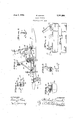
- This invention has for its object to provide a water vehicle in the nature of a floating velocipede, which may be impelled by the operation of pedals, but which is provided With a gas engine driving means capable of being cranked by the pedals.
- An object of the invention is to provide for steering such a water vehicle by means of a rudder attached to the propeller carrier and Y mounted in the rear of the propeller.
- Fig. 2 is a detailshowing the cross arm on the steering post for operating the tillers
- Fig. 3 is a plan view of the propeller and rudder with tiller connections
- Fig. 4 is'an enlarged view of one of the pontoon connections
- Fig. 5 is a detail view of the connection between one of the brace rods and the pontoon bracket with the parts disconnected;
- Fig. 6 is a sectional view of one of the connections between the square swinging arms and the pontoon brackets
- Fig. 7 is a plan view of a pontoon bracket.
- 10 indicates a tubular frame somewhat similar in construction to a bicycle frame having the usual saddle 11, handle bars 12 on a steeringv post 18 fitting in a steering head 1st and pedal cranks 15 with a sprocket wheel 16.
- semi No. 355,636 is a tubular frame somewhat similar in construction to a bicycle frame having the usual saddle 11, handle bars 12 on a steeringv post 18 fitting in a steering head 1st and pedal cranks 15 with a sprocket wheel 16.
- Each of these supporting brackets 18 is of channel shape, and has pivotally mounted between its parallel flanged members a pair of swinging arms 20, preferably of square tubular construction. When extended these arms 20 fit within the brackets 18 and bear against the upper walls thereof to form a rigid supporting joint for supporting the weight of the vehicle frame and rider on a pair of pontoons 21 mounted on the outer ends of the arms.
- the pontoons are preferably elongated floats of hollow sheet metal or of light woo-den construction or of other material, and they have brackets 22 extending across them and down their sides, where they are rigidly sccured by screws, said brackets being pivotally connected at the'top of the pontoons with the ends of the swinging arms 20.
- Brace rods 23 are pivotally connected at their upper ends to the upper end of the steering head 1 and the upper end of the seat frame, and their lower ends are detachably clamped to the brackets 22.
- the detachable clamping means for the swinging arms 20 and the brace rods 23 whereby they are rigidly connected with the brackets 22 form a novel feature of this invention.
- a screw stud is anchored in the end of the brace rod 23, or near the end of the swing- ,ing arm 20, and has a wing nut 51 threaded wing nut is tightened its flanged hub or projection fits within said opening and, being incapable of passing through the slot, effectually locks the parts in their engagement.
- the wing nut being incapable of removal from 5 the stud, is incapable of being lost and is ready for use at all times.
- the detachment is quickly efiected by backing the wing nut until the flanged hub or projection 55 is free from the opening 53,when the parts may be separated by the stud passing through the slot 5d.
- a yokedhanger bracket is securely mounted on the frame member 17 beneath the crank shaft bearing and pivotally carries at its forked end a gear-case 26 having a shaft 27 extending therethrough with a sprocket 28 on the outside driven by a chain 29 from the sprocket wheel 16.
- a shaft tube 34 clamped to thegear-case 26 carriesasha ft 32, on which is mounted a propeller 85,said shaft being driven by a gearing in the gearcase 26 from the shaft 27.
- a gas engine 56 is mounted in the frame 1-0 and has driving connectionthrough a 'chain and clutch, not shown, with the shaft 27 for driving the propeller and for being cranked by the turning of the pedal shaft, there being a ratchet connection permitting the'pedals to remain idle while the engine drives the propeller.
- the clutch and ratchet construction form the subject-matterof a separate application.
- the shaft tube 34 at about-the middle of its length, is provided with a coupling 3611a?- ing a connecting rod 37 pivotally connected thereto.
- the connecting rod 37 through a swinging bearing '38 pivotally mounted on the rear end of the frame -10,"a handle 39 being provided onthe endthereof for raising or lowering the propeller shaft, and a clamping screw 40 being provided in V the bearing forclamping the connecting 'rod in its adjustment.
- the "propeller shaft may be raised or lowered to bring thepropeller between the pontoons or depressedtoa greater or less extent and may-be-clampedin its adjustments.
- the steering postlg which carriesthe handle bars 12, isprovided atits lower end with a cross arm 57 and tiller cables 58 connected to the two ends thereof-p'ass through guides 59 on the bottom of the gearcase 26 and eXtend'to the opposite endsof a cross arm 60 on a rudder stem 61 of a rudder 62 pivotally mounted above and below inbearings formed by a rudder bracket-'63 secured to the end of the shaft tube 34.
- Yielding connections such as springs 64 in the tiller cables 58 permit of suflicient extension and contraction thereof to accommodate the change in angular position of the 65 up and securely locked in operative condition slides 7 by means of the fastening mechanism provided and-such fastening means is permanently attached and incapable of being lost.
- the invention provides for a collapsible pontoon with a propeller drive, which may be operated either manually or by the use of the gas engine. Nothwithsta-nding adjustability for the propeller shaft, provision is made for mounting the rudder in place thereon to be subject to the same adjustmentstherewith.
- a water. vehicle comprising a frame
- a water"vehicle comprising a frame, arms mounted on'the frame,'pontoons*pi votally mounted on the arms, brace rods detachably connecting theframe with the pontoons,
- a gas engine mounted'ontheframe, driving means between thegas engine and "the; propeller shaft'and' between thesprocket and the propeller shaft and a rudder mounted on the propeller shaft and connected with the steering post.
- a water vehicle comprising a frame in the nature of a bicycle frame having a saddle and a steering post with handle-bars, a pedal shaft having a sprocket, an adjustably mounted propeller shaft having driving connection with the sprocket, a rudder mounted on the propeller shaft behind the propeller thereof, and tiller cables having connection with the rudder and the handlebars.
- a water vehicle comprising a frame in the nature of a bicycle frame, having a saddle and a steering post with handle-bars, a pedal shaft having a sprocket, an adjustably mounted propeller shaft having driving connection with the sprocket, a rudder bracket mounted thereon, a rudder carried by the rudder bracket behind the propeller of the propeller shaft and having cross arms, cross arms on the lower end of the steering post, and tiller cables connecting the ends of the cross arms.
- a water vehicle comprising a frame in the nature of a bicycle frame having a saddle and a steering post with handle-bars, a pedal shaft having a sprocket, a gear-case pivotally mounted on the frame, a propeller shaft tube carried by the gear-case, a propeller shaft therein having a propeller on its end, driving means between the sprocket and the propeller shaft, means for raising and lowering the propeller shaft tube, rudder brackets on the propeller shaft tube, a rudder mounted therein behind the propeller and having cross arms, cross arms on the end of the steering post, and tiller cables guided on the gear-case and connecting the ends of the cross arms.
Landscapes
- Chemical & Material Sciences (AREA)
- Engineering & Computer Science (AREA)
- Combustion & Propulsion (AREA)
- Mechanical Engineering (AREA)
- Ocean & Marine Engineering (AREA)
- Body Structure For Vehicles (AREA)
Description
, June 3, 1930.
M. GORSKI WATER VEHICLE Filed April 16, 1929 //v I/ENTOR 0% ATTORNE w/ TVNESSES M gm Patented June 3, 1939 PATENT OFFICE MICHAEL GORSKI, OF MILWAUKEE, WISCONSIN, ASSIGNOB- TO BRINSMERE BOAT & CYCLE COMPANY, OF MILWAUKEE, WISCONSIN, A CORPORATION OF WISCONSIN WATER VEHICLE Application filed April 16,
This invention has for its object to provide a water vehicle in the nature of a floating velocipede, which may be impelled by the operation of pedals, but which is provided With a gas engine driving means capable of being cranked by the pedals. An object of the invention is to provide for steering such a water vehicle by means of a rudder attached to the propeller carrier and Y mounted in the rear of the propeller.
tion, the near pontoon having been removed;
Fig. 2 is a detailshowing the cross arm on the steering post for operating the tillers;
Fig. 3 is a plan view of the propeller and rudder with tiller connections;
Fig. 4 is'an enlarged view of one of the pontoon connections;
Fig. 5 isa detail view of the connection between one of the brace rods and the pontoon bracket with the parts disconnected;
Fig. 6 is a sectional view of one of the connections between the square swinging arms and the pontoon brackets, and
Fig. 7 is a plan view of a pontoon bracket.
In these drawings, 10 indicates a tubular frame somewhat similar in construction to a bicycle frame having the usual saddle 11, handle bars 12 on a steeringv post 18 fitting in a steering head 1st and pedal cranks 15 with a sprocket wheel 16. On the bottom horizontal frame member 17, which connects the lower end of the steering head with the pedal bracket and seat post brace are a pair of supporting brackets 18 preferably brazed or welded on the bottom of said member, one 59 being positioned near the steering head 14 1929. semi No. 355,636.
and the other near the rear end of said mem- 2 ber 17. Each of these supporting brackets 18 is of channel shape, and has pivotally mounted between its parallel flanged members a pair of swinging arms 20, preferably of square tubular construction. When extended these arms 20 fit within the brackets 18 and bear against the upper walls thereof to form a rigid supporting joint for supporting the weight of the vehicle frame and rider on a pair of pontoons 21 mounted on the outer ends of the arms.
The pontoons are preferably elongated floats of hollow sheet metal or of light woo-den construction or of other material, and they have brackets 22 extending across them and down their sides, where they are rigidly sccured by screws, said brackets being pivotally connected at the'top of the pontoons with the ends of the swinging arms 20. Brace rods 23 are pivotally connected at their upper ends to the upper end of the steering head 1 and the upper end of the seat frame, and their lower ends are detachably clamped to the brackets 22.
l/Vhen so connected the swinging arms 20 and the brace rods 23 with the brackets 22 form rigid lateral extensions of the frame construction with the pontoons 21 firmly and securely mounted at a distance from the center line to give great stability to the vehicle with its operator.
The detachable clamping means for the swinging arms 20 and the brace rods 23 whereby they are rigidly connected with the brackets 22 form a novel feature of this invention. A screw stud is anchored in the end of the brace rod 23, or near the end of the swing- ,ing arm 20, and has a wing nut 51 threaded wing nut is tightened its flanged hub or projection fits within said opening and, being incapable of passing through the slot, effectually locks the parts in their engagement.- The wing nut, being incapable of removal from 5 the stud, is incapable of being lost and is ready for use at all times. The detachment is quickly efiected by backing the wing nut until the flanged hub or projection 55 is free from the opening 53,when the parts may be separated by the stud passing through the slot 5d.
A yokedhanger bracket, not shown, is securely mounted on the frame member 17 beneath the crank shaft bearing and pivotally carries at its forked end a gear-case 26 having a shaft 27 extending therethrough with a sprocket 28 on the outside driven by a chain 29 from the sprocket wheel 16. A shaft tube 34 clamped to thegear-case 26 carriesasha ft 32, on which is mounted a propeller 85,said shaft being driven by a gearing in the gearcase 26 from the shaft 27.
A gas engine 56 is mounted in the frame 1-0 and has driving connectionthrough a 'chain and clutch, not shown, with the shaft 27 for driving the propeller and for being cranked by the turning of the pedal shaft, there being a ratchet connection permitting the'pedals to remain idle while the engine drives the propeller. The clutch and ratchet construction form the subject-matterof a separate application. v
The shaft tube 34, at about-the middle of its length, is provided with a coupling 3611a?- ing a connecting rod 37 pivotally connected thereto. The connecting rod 37 through a swinging bearing '38 pivotally mounted on the rear end of the frame -10,"a handle 39 being provided onthe endthereof for raising or lowering the propeller shaft, and a clamping screw 40 being provided in V the bearing forclamping the connecting 'rod in its adjustment. Thus the "propeller shaft may be raised or lowered to bring thepropeller between the pontoons or depressedtoa greater or less extent and may-be-clampedin its adjustments. The steering postlg, which carriesthe handle bars 12, isprovided atits lower end with a cross arm 57 and tiller cables 58 connected to the two ends thereof-p'ass through guides 59 on the bottom of the gearcase 26 and eXtend'to the opposite endsof a cross arm 60 on a rudder stem 61 of a rudder 62 pivotally mounted above and below inbearings formed by a rudder bracket-'63 secured to the end of the shaft tube 34. Yielding connections such as springs 64 in the tiller cables 58 permit of suflicient extension and contraction thereof to accommodate the change in angular position of the 65 up and securely locked in operative condition slides 7 by means of the fastening mechanism provided and-such fastening means is permanently attached and incapable of being lost. .The invention provides for a collapsible pontoon with a propeller drive, which may be operated either manually or by the use of the gas engine. Nothwithsta-nding adjustability for the propeller shaft, provision is made for mounting the rudder in place thereon to be subject to the same adjustmentstherewith.
bracket on said pontoons,-slotted-ears there i on having openings of larger diameter than T the slots, screw -studs on the armsand the brace rods capable-of entering the openings by way of the slots, and thumb n-uts on the screw "studs having projections to entersaid openings, said projections being too large to pass through the slots.
2. A water. vehicle comprising a frame,
armsmounte'd-on the frame, pontoons pivotal- 1y mounted .on the'arms, brace rods detache ably connecting the frame with the pontoons, andmeans for locking the armsand the brace rods "to the "pontoonscomprisinga bracket'on'said *pontoons having "the arms pivotally connected thereto,iprojecting ears on the bracket,screw studs onthe arms-and the brace i'rods respectively, there bBi-IlgzSlOtS in "the ears through which screw studsmay freely pass andopenings of larger; diameter than the slots communicating *therewith, thumb=nuts thread-ed on the screw studs, heads on the screw' studs preventing the -removal of the'thumb nuts, and flanged hub projections on the'thumb" nuts fitting within the openingsof the ears andincapable of removal through" the slots.
3. A water"vehiclecomprising a frame, arms mounted on'the frame,'pontoons*pi votally mounted on the arms, brace rods detachably connecting theframe with the pontoons,
steering and propellingmeans' mountedon r the frame, said deta chablebrace rods and arms permitting the pontoons -to fold with respect to the frame, and a gas engine onthe frame having driving connection with'the propelling means.
4. A water vehicle'comprising "a frame in the nature ofa bicycle frame having asaddle and a steering post with handle-barsya pedal shaft having a sprocket, a propeller shaft,
a gas engine mounted'ontheframe, driving means between thegas engine and "the; propeller shaft'and' between thesprocket and the propeller shaft and a rudder mounted on the propeller shaft and connected with the steering post.
7 5. A water vehicle comprising a frame in the nature of a bicycle frame having a saddle and a steering post with handle-bars, a pedal shaft having a sprocket, an adjustably mounted propeller shaft having driving connection with the sprocket, a rudder mounted on the propeller shaft behind the propeller thereof, and tiller cables having connection with the rudder and the handlebars.
6. A water vehicle comprising a frame in the nature of a bicycle frame, having a saddle and a steering post with handle-bars, a pedal shaft having a sprocket, an adjustably mounted propeller shaft having driving connection with the sprocket, a rudder bracket mounted thereon, a rudder carried by the rudder bracket behind the propeller of the propeller shaft and having cross arms, cross arms on the lower end of the steering post, and tiller cables connecting the ends of the cross arms.
7 A water vehicle comprising a frame in the nature of a bicycle frame having a saddle and a steering post with handle-bars, a pedal shaft having a sprocket, a gear-case pivotally mounted on the frame, a propeller shaft tube carried by the gear-case, a propeller shaft therein having a propeller on its end, driving means between the sprocket and the propeller shaft, means for raising and lowering the propeller shaft tube, rudder brackets on the propeller shaft tube, a rudder mounted therein behind the propeller and having cross arms, cross arms on the end of the steering post, and tiller cables guided on the gear-case and connecting the ends of the cross arms.
In testimony whereof, I afiix my signature.
MICHAEL GORSKI.
Priority Applications (1)
| Application Number | Priority Date | Filing Date | Title |
|---|---|---|---|
| US355636A US1761884A (en) | 1929-04-16 | 1929-04-16 | Water vehicle |
Applications Claiming Priority (1)
| Application Number | Priority Date | Filing Date | Title |
|---|---|---|---|
| US355636A US1761884A (en) | 1929-04-16 | 1929-04-16 | Water vehicle |
Publications (1)
| Publication Number | Publication Date |
|---|---|
| US1761884A true US1761884A (en) | 1930-06-03 |
Family
ID=23398205
Family Applications (1)
| Application Number | Title | Priority Date | Filing Date |
|---|---|---|---|
| US355636A Expired - Lifetime US1761884A (en) | 1929-04-16 | 1929-04-16 | Water vehicle |
Country Status (1)
| Country | Link |
|---|---|
| US (1) | US1761884A (en) |
Cited By (10)
| Publication number | Priority date | Publication date | Assignee | Title |
|---|---|---|---|---|
| US2714362A (en) * | 1952-05-28 | 1955-08-02 | Simon E Schroeder | Steering adaptor assembly for outboard motors |
| US2910035A (en) * | 1957-11-12 | 1959-10-27 | William R Johnson | Foot operated marine paddle wheel system |
| US2990804A (en) * | 1959-06-08 | 1961-07-04 | Jacob W Garehime | Collapsible water cycle |
| US3031692A (en) * | 1959-01-14 | 1962-05-01 | Monroe C Riek | Boat |
| FR2474995A2 (en) * | 1974-07-11 | 1981-08-07 | Beaulaton Jean | Pedal operated pleasure craft with auxiliary motor - has motor geared to main pedal drive through clutch |
| DE19933643A1 (en) * | 1999-07-17 | 2001-01-25 | Volker Meiswinkel | Swimming apparatus is for person partly lying in water and comprises operable frame, and has swim body together with hand grips at front end, forward drive and foot supports at rear end |
| US20150166158A1 (en) * | 2013-12-08 | 2015-06-18 | Bruce A. Wolfe | Pedal propulsion device for a watercraft |
| US9463857B1 (en) * | 2014-05-05 | 2016-10-11 | Schiller Sports, Inc. | Watercraft |
| US9650109B2 (en) | 2014-12-23 | 2017-05-16 | Schiller Sports, Inc. | Water bike |
| US11958577B1 (en) * | 2023-05-30 | 2024-04-16 | Moshe Katz | Modular boat |
-
1929
- 1929-04-16 US US355636A patent/US1761884A/en not_active Expired - Lifetime
Cited By (13)
| Publication number | Priority date | Publication date | Assignee | Title |
|---|---|---|---|---|
| US2714362A (en) * | 1952-05-28 | 1955-08-02 | Simon E Schroeder | Steering adaptor assembly for outboard motors |
| US2910035A (en) * | 1957-11-12 | 1959-10-27 | William R Johnson | Foot operated marine paddle wheel system |
| US3031692A (en) * | 1959-01-14 | 1962-05-01 | Monroe C Riek | Boat |
| US2990804A (en) * | 1959-06-08 | 1961-07-04 | Jacob W Garehime | Collapsible water cycle |
| FR2474995A2 (en) * | 1974-07-11 | 1981-08-07 | Beaulaton Jean | Pedal operated pleasure craft with auxiliary motor - has motor geared to main pedal drive through clutch |
| DE19933643A1 (en) * | 1999-07-17 | 2001-01-25 | Volker Meiswinkel | Swimming apparatus is for person partly lying in water and comprises operable frame, and has swim body together with hand grips at front end, forward drive and foot supports at rear end |
| US20150166158A1 (en) * | 2013-12-08 | 2015-06-18 | Bruce A. Wolfe | Pedal propulsion device for a watercraft |
| US9302755B2 (en) * | 2013-12-08 | 2016-04-05 | Bruce A. Wolfe | Pedal propulsion device for a watercraft |
| US9463857B1 (en) * | 2014-05-05 | 2016-10-11 | Schiller Sports, Inc. | Watercraft |
| US9650109B2 (en) | 2014-12-23 | 2017-05-16 | Schiller Sports, Inc. | Water bike |
| US10046841B2 (en) | 2014-12-23 | 2018-08-14 | Schiller Sports, Inc. | Water bike |
| US11958577B1 (en) * | 2023-05-30 | 2024-04-16 | Moshe Katz | Modular boat |
| WO2024246791A1 (en) * | 2023-05-30 | 2024-12-05 | Moshe Katz | A modular boat |
Similar Documents
| Publication | Publication Date | Title |
|---|---|---|
| US1761884A (en) | Water vehicle | |
| US4618020A (en) | Motorcycle | |
| CN110382342B (en) | Manpower-driven hydrofoil vehicle and using method | |
| US5088944A (en) | Collapsible water bike | |
| US5316508A (en) | Water bicycle | |
| US3709185A (en) | Amphibious motor bike | |
| TW201628893A (en) | Water bike | |
| US1920391A (en) | Water bicycle | |
| CN101878152A (en) | Ship propulsion device comprising a link mechanism and a horizontal propulsion fin | |
| US4543898A (en) | Two hulled motor to sail convertible boat | |
| US3211125A (en) | Combination rudder and propeller drive assembly | |
| US547422A (en) | Marine conveyance | |
| US637547A (en) | Marine velocipede. | |
| CN111683864B (en) | Two-wheeled bike with variable configuration | |
| DK301984A (en) | SAIL TO A BIKE | |
| US2296147A (en) | Marine velocipede | |
| JP2687126B2 (en) | Pillion frame structure for motorcycles | |
| US597348A (en) | Driving and steering attachment for bicycles | |
| US839476A (en) | Water transportation means. | |
| US1692354A (en) | Ice boat | |
| US1322403A (en) | Gbatibw bid onde | |
| DE482906C (en) | Motorbike or motorcycle that can be carried in a paddle boat without dismantling | |
| JP2838747B2 (en) | Easy-to-disassemble recreational water cycle | |
| KR101760091B1 (en) | Roof type amphibious bicycle | |
| US464227A (en) | Combined land and water vehicle |