US1761857A - Gauge for sewing machines - Google Patents
Gauge for sewing machines Download PDFInfo
- Publication number
- US1761857A US1761857A US298026A US29802628A US1761857A US 1761857 A US1761857 A US 1761857A US 298026 A US298026 A US 298026A US 29802628 A US29802628 A US 29802628A US 1761857 A US1761857 A US 1761857A
- Authority
- US
- United States
- Prior art keywords
- guide
- gauge
- sewing machines
- sewing
- edge
- Prior art date
- Legal status (The legal status is an assumption and is not a legal conclusion. Google has not performed a legal analysis and makes no representation as to the accuracy of the status listed.)
- Expired - Lifetime
Links
- 238000009958 sewing Methods 0.000 title description 11
- 238000010276 construction Methods 0.000 description 4
- 239000000463 material Substances 0.000 description 3
- 241001290610 Abildgaardia Species 0.000 description 1
- 101100504379 Mus musculus Gfral gene Proteins 0.000 description 1
- 238000006073 displacement reaction Methods 0.000 description 1
- 210000003811 finger Anatomy 0.000 description 1
- 239000004576 sand Substances 0.000 description 1
- 210000003813 thumb Anatomy 0.000 description 1
Images
Classifications
-
- D—TEXTILES; PAPER
- D05—SEWING; EMBROIDERING; TUFTING
- D05B—SEWING
- D05B35/00—Work-feeding or -handling elements not otherwise provided for
- D05B35/06—Work-feeding or -handling elements not otherwise provided for for attaching bands, ribbons, strips, or tapes or for binding
Definitions
- This invention relatestogauges for sewing machines and has for itsobject to provide an adjustable gauge which is more simple in construction and efficient in use than those heretofore proposed.
- Fig.:;2 is an end elevational view looking towards thesewing machineand illustratingsome of the parts-"shown inFig. 1 in turned'down' or inoperative position to permit ordinary sewing;
- FIG. 3I is a-yerti'cal sectional view taken as on the line 33 of l -and'lookingin the direction of the arrows.
- This invention is 'more particularly, di-
- I 1 indicates the throat'plate, 2fthefoot, 3 the needle; and ltheneedle 'baiiusuallyfound in, i sewing machines ofthis type;- while 5 is 'a gage the teeth of'a pinion 23.journalledin accomplish the results desired, as well as relever adapted tooscillate theneedle 3Ifrom sideto side to formjdiagonal or zigzag stitching, said lever having a depending portion 6 connected as througha link 7 with the sliding rod 8 disposed below and in substantially the same vertical plane with the main driving shaft 9 of the machine. 10 is the thread looper carried in prolongation of and at the end of the main driving shaft 9 and adapted to rotate beneath the throat plate 1 which is secured to the frame 11 of the sewing machine as by the screw 12.
- the gauge mechanism comprises the vere tically disposed supporting plate 15, secured as by the screws 16 to the bed plate of the machine, which is provided with the track 17 upon which slides the gauge unit generally indicated by'the numeral 20.
- the unit 20 has a base portion 21 on the bottom edge of which are cut rack teeth 22 adapted to enthe frame of the sewing machine and provided with a knob 24 integral with the pinion for turning the same and thus'causing the unit as a whole to slide onits track from left to right.
- i p i The baseportion 21 is provided with a slotway 25 extending horizontally and through'which freely passes a stud 26rigidly threaded into thesupporting'plate 15.
- This stud 26' carries a bracket member 27 55 having an out-turned end serving as a journal'forone end of a rod 28 the other end of which has rigidlyformed therewith a fixed member 29 serving as an edge guide having a-lugBOJadapted torest in an aperture 31 0 formed'thereforin the throat plate 1.
- edge guide 29 is curved to conform to the surface ofthethro'at' platefand the opposite side or edge is provided with'a fin ger piece32bywhi'ch said edge guide may readily be turned downwardly: about the centerof the'rod 28 as anaxisas shown in Fig.2. out of the Way of' any material upon which the' us'ual stitching is desired.
- the V 33 against the-fiat sides of which the end 34 of a spring contacts to hold the edge guide 29 in either operative or inoperative position, the other end of said spring being secured about the stud 26.
- the gaugeunit has an outstanding end portion or rib constituting the braid guide 7 i which is adapted to closely and contactc p 7 V that no part of-the braid guide will be above 4 the horizontalplane. of. the top of the throat plate and 1nthe way,ofmater1al bemgsewed
- Thelower section of the braid guide is aper- 1 tured to permit the edge guide rod28 to pass therethroughand be supported therebyy said aperture providing a close. sliding. fit with ing of the gauge unit as aowhole on its sup--v cportingplate -15; 'r
- the rod.53:is Ora length suf-.
- fioient t0 extend-beyond thebraid guide 40 and has integrally formed, at the end, thereof a pressure arm 55xha'ving associatedthere; with a thumb piece 56 as will be clear from the drawings.
- Thatistosayythe rod 53 which is preferably ofsquare cross section;
- lgA gauge'jgdevice forlsewing machines comprising a support secured to saidfmae V chineg a gaugeunit 'horizontallymovable ⁇ over said support; an edge guide provided with means for positively-securing thesaIne "i V againsthorizontal;displacementg 'fa divided; I braid :guide (the, lower" portion fixed. with ire: f if spectzto said unitbut the upper portionimov brackets carried byasaidunit; a'squaried-sh'aft F passing through. said. brackets and provided 1 id Vb jd g.u-ideT-;z "sand: springzxcontrolled 1 means for,securingsaidedge guideandpres isure arm.
- Aflgauge 'device ifor sewingxmachines support secured'tol said; machine; af gauge I an ,edge guide pr'ovided-T with, dual-means for -f I tal dis ueemenaone of a-reaps seme -g g n a tr en ne a by eeo said raek' tssa .pressurearm'inte j gral withisaid; shaft andia ptedto campy the'space' ibetween said Ledge, guide and said blitaiidrl guide; and;:spriiigEcontro1led 'means 51-39 I V 1 00 'able with respect theretoina-ivertical plane;
- a gauge device for sewing machines provided with a throat plate having an opening in its work face-said device comprising a support secured'to said machine; a gauge unit horizontally movable over said support; an edge guideprovided with means for positively securing theisame against horizontal displacement said means engaging the throat plate opening; a divided braid guide the lower portion apertured to supportinglyreceive a portion, of said edge guide and fixed with respect to-said unit but the upper portion movable with respect thereto in a vertical plane; brackets carried by said unit; a squared shaft passing through said brackets and provided with threads at one end engaging a nut confinedby one of said brackets; a pressure arm integral with said shaft and adapted to occupy the space between said sedge guide and said braid'guide and spring controlled means for securing said edge guide and pressure arm in operative and inoperative positions.
Landscapes
- Engineering & Computer Science (AREA)
- Textile Engineering (AREA)
- Sewing Machines And Sewing (AREA)
Description
1 3,}1930- A. M. WENZEL 1,751,357
GAUGE FOR SEWING MACHINES Filed Aug. 7, 1928 3nveutor 1M TVenze Patented June 3, 1930 f ANnA'iAnELINE wEN'zEL, or BROOKLYN, NEW YORK GAUGE non SEWING 'MAoHINns Application filed August 7, 1928'. Serial No. 298,026.
- This invention relatestogauges for sewing machines and has for itsobject to provide an adjustable gauge which is more simple in construction and efficient in use than those heretofore proposed.
With these and other. objectsin view the invention consists-in the novel details of constructionand combinations of parts as will be more fully hereinafter disclosed and particu-v 1O larly pointedout in the claims.
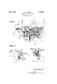
Referring to the accompanying drawings forming a part of this specification in which likeinumerals designate like parts in allthe views: 1 .1. 1 'Q F'g. 1 is apers ective viewlillustratingthe invention as "app ied to a sewing machine;
Fig.":;2 is an end elevational view looking towards thesewing machineand illustratingsome of the parts-"shown inFig. 1 in turned'down' or inoperative position to permit ordinary sewing; and
3 Fig. 3Iis a-yerti'cal sectional view taken as on the line 33 of l -and'lookingin the direction of the arrows.
as This invention is 'more particularly, di-
rected'to gauges for use with sewing machines-adapted to sewwbraid such, as on hats and contemplates a :gaugewhich is an improvement overthat disclosed inmy co-pend- "3o ingapplicationiserial*No;240,812 filed Dec.
17, 1927, and entitled Adjustable gauges for "sewing-machines. One of the objects of this vinvention'is to provide a construction the parts of which arereadily turned out ofoperative ipositions when ordinary sewing is tobe done by themachine thus giving more spac e'forthe work being sewed 1 p -Ano her object of this invention is to provide. a construction'whichis lessgcumbersome, has fewer parts, and permits greater adjust- I ability with more ease than'those heretofore proposed," while "atthe same time maintaining l inherent strength and necessary rigidity to ducing the weight of the 'niachine. I 1 indicates the throat'plate, 2fthefoot, 3 the needle; and ltheneedle 'baiiusuallyfound in, i sewing machines ofthis type;- while 5 is 'a gage the teeth of'a pinion 23.journalledin accomplish the results desired, as well as relever adapted tooscillate theneedle 3Ifrom sideto side to formjdiagonal or zigzag stitching, said lever having a depending portion 6 connected as througha link 7 with the sliding rod 8 disposed below and in substantially the same vertical plane with the main driving shaft 9 of the machine. 10 is the thread looper carried in prolongation of and at the end of the main driving shaft 9 and adapted to rotate beneath the throat plate 1 which is secured to the frame 11 of the sewing machine as by the screw 12.
7 By disposing the sliding rod 8 in substantially the same vertical plane with the main drive. shaft 9, the entire gaugemechanism canbe mounted closer to the needle 3 than those heretofore proposed, and particularly that disclosed in my co-pending application.
7 The gauge mechanism comprises the vere tically disposed supporting plate 15, secured as by the screws 16 to the bed plate of the machine, which is provided with the track 17 upon which slides the gauge unit generally indicated by'the numeral 20. The unit 20 has a base portion 21 on the bottom edge of which are cut rack teeth 22 adapted to enthe frame of the sewing machine and provided with a knob 24 integral with the pinion for turning the same and thus'causing the unit as a whole to slide onits track from left to right. i p i The baseportion 21 is provided with a slotway 25 extending horizontally and through'which freely passes a stud 26rigidly threaded into thesupporting'plate 15.
This stud 26'carries a bracket member 27 55 having an out-turned end serving as a journal'forone end of a rod 28 the other end of which has rigidlyformed therewith a fixed member 29 serving as an edge guide having a-lugBOJadapted torest in an aperture 31 0 formed'thereforin the throat plate 1. One
side/of the edge guide 29 is curved to conform to the surface ofthethro'at' platefand the opposite side or edge is provided with'a fin ger piece32bywhi'ch said edge guide may readily be turned downwardly: about the centerof the'rod 28 as anaxisas shown in Fig.2. out of the Way of' any material upon which the' us'ual stitching is desired. "The V 33against the-fiat sides of which the end 34 of a spring contacts to hold the edge guide 29 in either operative or inoperative position, the other end of said spring being secured about the stud 26. p The gaugeunit has an outstanding end portion or rib constituting the braid guide 7 i which is adapted to closely and contactc p 7 V that no part of-the braid guide will be above 4 the horizontalplane. of. the top of the throat plate and 1nthe way,ofmater1al bemgsewed Thelower section of the braid guide is aper- 1 tured to permit the edge guide rod28 to pass therethroughand be supported therebyy said aperture providing a close. sliding. fit with ing of the gauge unit as aowhole on its sup--v cportingplate -15; 'r
At the u aportion of the base member 21 ,.-and near; theright. hand end thereof there is provided an ex ending bracket 1 provided'witha slot; 51'to confiningly, receive a knurlednut 52 threaded: on the rod 53 eX= tending horizontally through said bracket 3 50 to and throughflanother bracket :5 1' dismember 21. The rod.53:is Ora length=suf-.,
fioient t0 extend-beyond thebraid guide 40 and has integrally formed, at the end, thereof a pressure arm 55xha'ving associatedthere; with a thumb piece 56 as will be clear from the drawings. Thatistosayythe rod 53 which is preferably ofsquare cross section;
and the braid guide 40.: Tosecure the necessary pressure between the pressure arm 55 and the Work passing over the throat plate 1', the rod-53is provided'with' anut 57 'havinga square aperture; to slidingly' but rotatably elrligage Iiaid rod," said nut being" disposed ereon etween the branches of the bracket lgulde the we p rtmn fix d m p g to. I
S d itbutthe'iippe iportionE' lio bliwith 5 4 and adapted to have itsflat sidesengaged by vleaf spring ,58 carried by said bracket. By means of-thethumb piece 5 ,6theipressure arm and therod 53 may be jrotatedquickly 4 7 5 and readil 1a; bring-said pressure arm down i into inoperative position asindic'ated' in Fig.
' 2 out offlthe Way; ofjflat material up'on which stitching is desired; f'; Y It thus results that by this invention there I isv provided 3 a jfixedf edgep guidei 29,:aYbraid wise into an inoperative position. The pres-I said'rod, so asnotto ihterfere with the slid 7 manded r by the claims.
posed near the left handend 'ofsaid base unit horizontally movable ever said support;
alsok-bereadily movedout of its operative poi -i enduthe uppe pertio h d; guide swung" about "in a vertical plane like? sure arm is readily and rapidly adjusted .toif 52 and all ofthe partsare disposed in ver-- takeniup by the gauge mechanism tohandi capzthe feed of material totheneedle3;
It is obvious that those'lskilled inthe-art 'maywvary'thedetails of construction asw'en u as arrangementsof :part's without departing p from'the spirit'of the inventionand itis 7 therefore desiredanot "to i be; limitedito; the foregoing disclosure except as may 1 bade; I
:What' is; claimed is:" L
lgA gauge'jgdevice forlsewing machines comprising a support secured to saidfmae V chineg a gaugeunit 'horizontallymovable} over said support; an edge guide provided with means for positively-securing thesaIne "i V againsthorizontal;displacementg 'fa divided; I braid :guide (the, lower" portion fixed. with ire: f if spectzto said unitbut the upper portionimov brackets carried byasaidunit; a'squaried-sh'aft F passing through. said. brackets and provided 1 id Vb jd g.u-ideT-;z "sand: springzxcontrolled 1 means for,securingsaidedge guideandpres isure arm. in operative and {inoperative posig tiOIISL' f v .7 i2. Aflgauge 'device ifor sewingxmachines support secured'tol said; machine; af gauge I an ,edge guide pr'ovided-T with, dual-means for -f I tal dis ueemenaone of a-reaps seme -g g n a tr en ne a by eeo said raek' tssa .pressurearm'inte j gral withisaid; shaft andia ptedto campy the'space' ibetween said Ledge, guide and said blitaiidrl guide; and;:spriiigEcontro1led 'means 51-39 I V 1 00 'able with respect theretoina-ivertical plane;
for. securing said edge guide and pressure arm in operative and inoperative positions.
3. A gauge device for sewing machines provided with a throat plate having an opening in its work face-said device comprising a support secured'to said machine; a gauge unit horizontally movable over said support; an edge guideprovided with means for positively securing theisame against horizontal displacement said means engaging the throat plate opening; a divided braid guide the lower portion apertured to supportinglyreceive a portion, of said edge guide and fixed with respect to-said unit but the upper portion movable with respect thereto in a vertical plane; brackets carried by said unit; a squared shaft passing through said brackets and provided with threads at one end engaging a nut confinedby one of said brackets; a pressure arm integral with said shaft and adapted to occupy the space between said sedge guide and said braid'guide and spring controlled means for securing said edge guide and pressure arm in operative and inoperative positions. o
Intestimony whereof I afiix In signature.
' ANNA -MADELINE WENZEL.
Priority Applications (1)
| Application Number | Priority Date | Filing Date | Title |
|---|---|---|---|
| US298026A US1761857A (en) | 1928-08-07 | 1928-08-07 | Gauge for sewing machines |
Applications Claiming Priority (1)
| Application Number | Priority Date | Filing Date | Title |
|---|---|---|---|
| US298026A US1761857A (en) | 1928-08-07 | 1928-08-07 | Gauge for sewing machines |
Publications (1)
| Publication Number | Publication Date |
|---|---|
| US1761857A true US1761857A (en) | 1930-06-03 |
Family
ID=23148686
Family Applications (1)
| Application Number | Title | Priority Date | Filing Date |
|---|---|---|---|
| US298026A Expired - Lifetime US1761857A (en) | 1928-08-07 | 1928-08-07 | Gauge for sewing machines |
Country Status (1)
| Country | Link |
|---|---|
| US (1) | US1761857A (en) |
-
1928
- 1928-08-07 US US298026A patent/US1761857A/en not_active Expired - Lifetime
Similar Documents
| Publication | Publication Date | Title |
|---|---|---|
| US1761857A (en) | Gauge for sewing machines | |
| US3216383A (en) | Device for sewing trimmings | |
| US2247383A (en) | Convertible flat-bed cylinder arm sewing machine | |
| US2618230A (en) | Auxiliary feeding means for hosiery seamers | |
| US1259324A (en) | Sewing-machine attachment. | |
| US1299143A (en) | Drip-pan for sewing-machines. | |
| US2809599A (en) | Apparatus for attaching endless bands to garments | |
| US2247382A (en) | Sewing machine feed mechanism | |
| US2526482A (en) | Thread clamp for chain stitch sewing machines | |
| US2486910A (en) | Work guide for sewing leather goods | |
| US2114075A (en) | Fagoting stitching machine | |
| US767301A (en) | Sewing-machine guide. | |
| US2268799A (en) | Sewing mechanism for stitching wire eye fasteners | |
| US1764573A (en) | Sewing-machine work support | |
| US2646759A (en) | Folder for blindstitch sewing machines | |
| US1984937A (en) | Pinking attachment or machine | |
| US2239189A (en) | Adjustable gauge fob sewing | |
| US1837468A (en) | Sewing machine feeding mechanism | |
| US3132611A (en) | Buttonhole attachment for zigzag sewing machines | |
| US1949332A (en) | Binder support for sewing machines | |
| US3295484A (en) | Sewing machine triple feeder attachment for stitching elastic to cloth pieces | |
| GB885779A (en) | Improvements relating to sewing machines | |
| US2829614A (en) | Work-table height adjusting means for blind-stitch sewing machines | |
| US56641A (en) | Improvement in sewing-machines | |
| US1071743A (en) | Garment-staying device. |