US1761855A - Electric-current-generating apparatus - Google Patents
Electric-current-generating apparatus Download PDFInfo
- Publication number
- US1761855A US1761855A US204169A US20416927A US1761855A US 1761855 A US1761855 A US 1761855A US 204169 A US204169 A US 204169A US 20416927 A US20416927 A US 20416927A US 1761855 A US1761855 A US 1761855A
- Authority
- US
- United States
- Prior art keywords
- circuit
- brushes
- current
- winding
- generator
- Prior art date
- Legal status (The legal status is an assumption and is not a legal conclusion. Google has not performed a legal analysis and makes no representation as to the accuracy of the status listed.)
- Expired - Lifetime
Links
- 238000004804 winding Methods 0.000 description 29
- 230000003247 decreasing effect Effects 0.000 description 5
- 230000004048 modification Effects 0.000 description 3
- 238000012986 modification Methods 0.000 description 3
- 230000005284 excitation Effects 0.000 description 2
- 230000004907 flux Effects 0.000 description 2
- 240000002878 Prunus cerasus Species 0.000 description 1
- 208000014769 Usher Syndromes Diseases 0.000 description 1
- 239000004020 conductor Substances 0.000 description 1
- 238000006073 displacement reaction Methods 0.000 description 1
- 230000001939 inductive effect Effects 0.000 description 1
- 230000007935 neutral effect Effects 0.000 description 1
- 230000001105 regulatory effect Effects 0.000 description 1
- 238000003466 welding Methods 0.000 description 1
Images
Classifications
-
- B—PERFORMING OPERATIONS; TRANSPORTING
- B23—MACHINE TOOLS; METAL-WORKING NOT OTHERWISE PROVIDED FOR
- B23K—SOLDERING OR UNSOLDERING; WELDING; CLADDING OR PLATING BY SOLDERING OR WELDING; CUTTING BY APPLYING HEAT LOCALLY, e.g. FLAME CUTTING; WORKING BY LASER BEAM
- B23K9/00—Arc welding or cutting
- B23K9/10—Other electric circuits therefor; Protective circuits; Remote controls
- B23K9/1006—Power supply
-
- H—ELECTRICITY
- H02—GENERATION; CONVERSION OR DISTRIBUTION OF ELECTRIC POWER
- H02K—DYNAMO-ELECTRIC MACHINES
- H02K23/00—DC commutator motors or generators having mechanical commutator; Universal AC/DC commutator motors
- H02K23/26—DC commutator motors or generators having mechanical commutator; Universal AC/DC commutator motors characterised by the armature windings
- H02K23/36—DC commutator motors or generators having mechanical commutator; Universal AC/DC commutator motors characterised by the armature windings having two or more windings; having two or more commutators; having two or more stators
Definitions
- My invention relates to a current generating apparatus having the characteristics of automatically decreasing the voltage as the delivered current increases, one application of such apparatus being to furnish the current for an arc welding circuit.
- the reason for decreasing the generating voltage with increase of current in the arc circuit is well understood and it has heretofore been proposed to accomplish this result by deco mpounding means in the form of a multipliclty of windings per pole or by employing an additional set of poles.
- the object of my invention is to avoid the use of such windings and extra poles and to thereby secure a decreased size of the generator and decreased field losses.
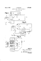
- FIG. 1 diagrammatically illustrates a current generating apparatus for the purpose mentioned, which embodies my invention
- Figure 2 illustrates a modified form of apparatus
- Figure 3 a modification in the armature of the machine of Figure 1.
- 1 represents a direct current generator having commuted winding 2 and field orexciting winding 3.
- A. pair of brushes 4, 5, cooperating with the commuted Winding are in series circuit with exciting winding 3 and a source of constant potential 6 (shown as a storage battery) through adjustable resistance 7.
- the brushes 4, 5 are preferably disposed coaxially with the exciting winding 3 or along the line parallel to the axis of that winding, as indicated by dotted lines.
- a pair of brushes 8, 9 also cooperate with the commuted winding 2 and are displaced from the brushes 4, 5 preferablyby an angle of substantially 90 electrical degrees.
- the arcing circuit 10 is connected to the brushes 8, 9, the arcing point being diagrammatically indicated at 11. I preferably include in this arcing circuit an' inductance 12 and may provide the generator with a winding 13 located in the axis of the brushes 8, 9 and connected in the arcing-circuit in parallel with the inductance 12 through adjustable resistance 14.
- the brushes 4, 5 are so shifted as to maintain their axis in parallelism with the axis of the field winding 3. Placing the brush axis at an angle to the field winding axis alters both the no-load voltage and shortcircuit current of the generator.
- inductance 12 the function of inductance 12 is to prevent sudden changes in the total effective resistance of the arc circuit when the arc resistance suddenly changes.
- I cause the machine to respond more quickly to current changes in the arc circuit because the circuit in the less inductive branch of the two commuted windings, as shown in Figure 3, one of these windings being connected in the exciting circuit and the other in the load circuit.
- This arrangement enables me to so design the windings as to secure somewhat better commutation since it is then possible to provide the winding connected to the brushes 4, 5 with only a small number of turns.
- I may secure this voltage from a small generator whose field winding carries the load current, and this modification is illustrated in Figure 2, in which the auxiliary generator 15 having field coil 16 has its armature connected in series with a source of constant potential 6 and the exciting winding 3 and in such direction that the generator voltage opposes the voltage of the source. 6.
- the magnitude of the generator voltage may be" varied by shifting. the brushes 17 18 from the neutral position shown in the drawings in such manner as to either change their angular relation to the field or their space displacement.
- the source ofconstant potential may, in the apparatus of either Figures 1 or 2, be a constant potential generator.
- a direct current generator provided with an exciting circuit comprising an ex clting winding and brushes, an output circuit comprislng a set of working brushes displaced from the exciting brushes, an wlnding on the generator displaced from the excltlng winding and in circuit the workingbr'ushes, and an inductance connect ed in the output circuit in shunt to said aunihary winding.
- a direct current generator provided withan exciting circuit comprising an exciting winding and brushes, an output circuit comprising a set of working brushes displaced from the exciting brushes, an auxillary winding on the generator, an inductance 1n 'the output circuit, and a resistance, said aux-' iliary winding-and resistance being connected in series and to the load circuit in shunt with the inductance.
Landscapes
- Engineering & Computer Science (AREA)
- Power Engineering (AREA)
- Physics & Mathematics (AREA)
- Plasma & Fusion (AREA)
- Mechanical Engineering (AREA)
- Synchronous Machinery (AREA)
Description
June 3, 1930. w c s 1,761,855
ELECTRIC CURRENT GENERATING APPARATUS Filed July 8, 1927 INVENTOR ATTORNEY Patented June 3, 1930 UNITED STATES PATENT OFFICE- HANS WEICHSEL, OF ST. LOUIS, MISSOURI, ASSIGNOR TO WAGNER ELECTRIC CORPORA- TION, OF ST. LOUIS, MISSOURI, A. CORPORATION OF DELAWARE ELECTRIC-CURRENT-GE1\TEIRATI1\TG APPARATUS Application filed July 8, 1927. Serial No. 204,169.
My invention relates to a current generating apparatus having the characteristics of automatically decreasing the voltage as the delivered current increases, one application of such apparatus being to furnish the current for an arc welding circuit. The reason for decreasing the generating voltage with increase of current in the arc circuit is well understood and it has heretofore been proposed to accomplish this result by deco mpounding means in the form of a multipliclty of windings per pole or by employing an additional set of poles. The object of my invention is to avoid the use of such windings and extra poles and to thereby secure a decreased size of the generator and decreased field losses.
In the accompanying drawings Figure 1 diagrammatically illustrates a current generating apparatus for the purpose mentioned, which embodies my invention; Figure 2 illustrates a modified form of apparatus; and Figure 3 a modification in the armature of the machine of Figure 1.
Referring to Figure 1, 1 represents a direct current generator having commuted winding 2 and field orexciting winding 3. A. pair of brushes 4, 5, cooperating with the commuted Winding, are in series circuit with exciting winding 3 and a source of constant potential 6 (shown as a storage battery) through adjustable resistance 7. The brushes 4, 5 are preferably disposed coaxially with the exciting winding 3 or along the line parallel to the axis of that winding, as indicated by dotted lines. A pair of brushes 8, 9 also cooperate with the commuted winding 2 and are displaced from the brushes 4, 5 preferablyby an angle of substantially 90 electrical degrees. The arcing circuit 10 is connected to the brushes 8, 9, the arcing point being diagrammatically indicated at 11. I preferably include in this arcing circuit an' inductance 12 and may provide the generator with a winding 13 located in the axis of the brushes 8, 9 and connected in the arcing-circuit in parallel with the inductance 12 through adjustable resistance 14.
Referring to the operation of the apparatus of Figure 1, no voltage is generated across the brushes 4, 5 when the arcing circuit is open since their axis coincides with the axis of the exciting winding 3, and under this condition the excitation of the win-ding 3 is due solely to the substantially constant potential of the battery .6. When the arcing circuit is closed and current drawn from the brushes 8, 9, and armature flux is set up in the axis of these brushes which results in a voltage being generated in the armature conductors which appears at the brushes 4, 5. If winding 18 is employed it carries part of the output current, and the flux in the axis of the brushes 8, 9 may be increased or decreased depending upon th direction of connection of the winding. The direction of connection of the source of constant potential 6 to the brushes 4, 5 is such that the voltage tage ampere characteristics of the arc circuit can be varied by shifting the brushes 4, 5.
If it is desired to increase the short-circuit current without changing the no-load voltage at 8, 9, the brushes 4, 5 are so shifted as to maintain their axis in parallelism with the axis of the field winding 3. Placing the brush axis at an angle to the field winding axis alters both the no-load voltage and shortcircuit current of the generator.
As is known, the function of inductance 12 is to prevent sudden changes in the total effective resistance of the arc circuit when the arc resistance suddenly changes. By, placing the winding 13 in shunt to the inductance 12, I cause the machine to respond more quickly to current changes in the arc circuit because the circuit in the less inductive branch of the two commuted windings, as shown in Figure 3, one of these windings being connected in the exciting circuit and the other in the load circuit. This arrangement enables me to so design the windings as to secure somewhat better commutation since it is then possible to provide the winding connected to the brushes 4, 5 with only a small number of turns.
Instead of securing the voltage proportional to the load current by means of brushes 4, 5 on the armature of the generator, I may secure this voltage from a small generator whose field winding carries the load current, and this modification is illustrated in Figure 2, in which the auxiliary generator 15 having field coil 16 has its armature connected in series with a source of constant potential 6 and the exciting winding 3 and in such direction that the generator voltage opposes the voltage of the source. 6. The magnitude of the generator voltage may be" varied by shifting. the brushes 17 18 from the neutral position shown in the drawings in such manner as to either change their angular relation to the field or their space displacement.
It will be understood that in lieu of a storage battery 6 the source ofconstant potential may, in the apparatus of either Figures 1 or 2, be a constant potential generator.
It will also be understood that a change in the voltage ampere characteristics of the arc ing circuit may be made by shifting the brushes 8, 9 and also by changing the magnitude of the resistance 7 in the exciting circuit. I am aware that modifications may be made 1n the apparatus herein described without departing from the principle of my invention and I do not therefore intend that its scope be limited other than by the appended claims.
Having fully described my invention, what I claim as new and desire to secure by Letters Patent of the United States is:
1. A direct current generator provided with an exciting circuit comprising an ex clting winding and brushes, an output circuit comprislng a set of working brushes displaced from the exciting brushes, an wlnding on the generator displaced from the excltlng winding and in circuit the workingbr'ushes, and an inductance connect ed in the output circuit in shunt to said aunihary winding.
2. A direct current generator provided withan exciting circuit comprising an exciting winding and brushes, an output circuit comprising a set of working brushes displaced from the exciting brushes, an auxillary winding on the generator, an inductance 1n 'the output circuit, and a resistance, said aux-' iliary winding-and resistance being connected in series and to the load circuit in shunt with the inductance.
3. The combination with an arcing circuit comprising an inductance, of a generator for supplying current to said circuit, and means for regulating said current comprising a winding connected in the arc circuit in shunt to the inductance and adapted to decrease the excitation of the generator upon the increase of current in that circuit, the time constant of the inductance branch being greater than that of the other branch.
4:. The combination with an arcing circuit comprising an inductance, of a direct current generator for supplying current tosaid circuit, said generator being provided with an exciting circuit comprising an exciting'wind-
Priority Applications (1)
| Application Number | Priority Date | Filing Date | Title |
|---|---|---|---|
| US204169A US1761855A (en) | 1927-07-08 | 1927-07-08 | Electric-current-generating apparatus |
Applications Claiming Priority (1)
| Application Number | Priority Date | Filing Date | Title |
|---|---|---|---|
| US204169A US1761855A (en) | 1927-07-08 | 1927-07-08 | Electric-current-generating apparatus |
Publications (1)
| Publication Number | Publication Date |
|---|---|
| US1761855A true US1761855A (en) | 1930-06-03 |
Family
ID=22756913
Family Applications (1)
| Application Number | Title | Priority Date | Filing Date |
|---|---|---|---|
| US204169A Expired - Lifetime US1761855A (en) | 1927-07-08 | 1927-07-08 | Electric-current-generating apparatus |
Country Status (1)
| Country | Link |
|---|---|
| US (1) | US1761855A (en) |
Cited By (1)
| Publication number | Priority date | Publication date | Assignee | Title |
|---|---|---|---|---|
| US3291960A (en) * | 1963-12-21 | 1966-12-13 | Messer Griesheim Gmbh | Control appliance for sources of welding current |
-
1927
- 1927-07-08 US US204169A patent/US1761855A/en not_active Expired - Lifetime
Cited By (1)
| Publication number | Priority date | Publication date | Assignee | Title |
|---|---|---|---|---|
| US3291960A (en) * | 1963-12-21 | 1966-12-13 | Messer Griesheim Gmbh | Control appliance for sources of welding current |
Similar Documents
| Publication | Publication Date | Title |
|---|---|---|
| US1761855A (en) | Electric-current-generating apparatus | |
| US2227678A (en) | Arc welder | |
| US1962691A (en) | Dynamo electric machine | |
| US1774304A (en) | Dynamo-electric machine | |
| US2180700A (en) | Direct-current arc-welding generator | |
| US1418707A (en) | Constant-current generator for arc welding | |
| US1571908A (en) | Electrical system | |
| US1882162A (en) | Device for connecting and switching the windings of dynamos | |
| US2274356A (en) | Polarity control system | |
| US1374565A (en) | Alternating-current commutator-motor | |
| US2662999A (en) | Electric motor of the metadyne type | |
| US1976782A (en) | Dynamo electric machine | |
| US1887496A (en) | Welding apparatus | |
| US1485742A (en) | Generator system | |
| US1622567A (en) | Alternating-current motor | |
| US1189703A (en) | Alternating-current motor. | |
| US1731425A (en) | Alternating-current commutator machine | |
| US1711844A (en) | Dynamo-electric machine | |
| US1301640A (en) | System for the transformation of electrical energy. | |
| US2364933A (en) | Dynamoelectric machine | |
| SU1200363A1 (en) | Synchronous generator | |
| SU282495A1 (en) | Device for improving the commutation of direct current electric machines | |
| GB270032A (en) | Improvements in generators for electric arc-welding | |
| US1476575A (en) | Dynamo-electric machine | |
| SU43454A1 (en) | DC generator |